1
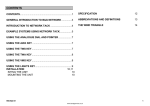
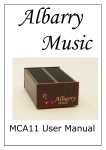
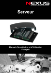
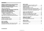
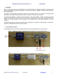
Dataline Databox SD
User Manual
For software version 1.01
Stowe Marine Limited
235 Bentley Way, LYMINGTON, SO41 8JW
Tel: 01590 610071
Fax: 01590 610072
email: [email protected]
www.stowemarine.com
Introduction
Congratulations on your purchase of the Databox SD from Stowe
Marine. This Databox combines clever thinking with incredibly
simple operation, and represents Stowe’s commitment to
providing customers with the finest products.
The Dataline Databox SD calculates Boat Speed, Depth, Sea
Temperature and Battery Volts when connected to compatible
sensors. It will also combine an additional NMEA input of data from
other instruments, such as Mast Head Unit, GPS or Compass.
The Databox SD can be used with any Stowe Speed and Depth
sensors and can also be used with many sensors from other
manufactures, (setting up via PC connected to USB may be
necessary).
Before you begin using your new Stowe Databox, please take the
time to read this manual to help you achieve the full potential.
Certification
This device meets requirements for CFR47 Part 15 of
the FCC limits for Class B equipment, and meets the
standards set out in European Standard EN 60945:
1997 IEC 945: 1996 for maritime navigation and
radiocommunication equipment and systems.
Disclaimer
Stowe Marine Limited accept no responsibility for the use of this
equipment. This equipment is not designed to replace conventional
navigation procedures. Information in this document is subject to
change without notice. Stowe Marine Limited reserve the right to
change its products and documentation without obligation to notify
any person or organisation of such changes.
Installation
The Databox SD must be mounted in a dry location with easy
access. All cables should be supported with clips on the bulkhead
close to the Databox opening.
Power Supply
This unit is designed to operate on a 12 volt system. An external
fuse MUST be connected with a MAXIMUM of 2 Amp rating.
Wind, GPS or Heading NMEA Input
This input can be used to ‘multiplex’ data into the Databox SD data
stream. To connect more than one device, a further NMEA
Combiner/Multiplexer must be used.
When using the Stowe NMEA Mast Head Unit, the Red wire
connects together with the +12V input and a link must be
connected between the 0V input and NMEA In B. See diagram on
last page for details.
Dataline Databus
This unit is designed to be used with the Stowe Dataline GX
displays, but attention has also been taken to make it backwards
compatible with older Dataline displays and also standard NMEA.
For Dataline GX displays, simply connect colour for colour for Red,
Black, White, Green and Brown. For older displays, connect colour
for colour, but also add a link between Black and Green. On older
Dataline displays with an orange right hand lighting button, the unit
must be set to ‘old Dataline’ via a PC connected to USB.
For NMEA output, use White as NMEA ‘A’, signal or + and Black as
NMEA ‘B’, return or ground.
Boat Speed/Log Sensor
The sensor must be positioned so that it is always under water, near
the centreline but at least 150mm away from the keel either side. In a
sailing yacht a position 150mm forward of the keel is preferable in
order to minimise tack to tack speed inaccuracies, caused by flow
past the leading edge. For powered vessels, position just ahead of
the engines for access, minimal electrical interference, and correct
speed function. Do not put in line with the propeller/s.
Recommended positions:
The hole for the skin fitting should be positioned well clear of any
internal frames or stringers. Keep clear of strop lifting points and
areas where damage could result from trailing or launching. Ensure
good access for removal of the paddlewheel assembly and the
subsequent mopping up of water spilled. Drill a small pilot hole first
and check its location inside and out, then using a 45mm (1¾")
diameter cutter in a hand or electric drill cut the required hole.
Assemble the skin fitting and nut using a good sealing compound
such as Sikaflex to make watertight. Do not over tighten the nut.
The paddlewheel transducer should be installed in the skin fitting
with the handle pointing fore and aft. Any other alignment may give
faulty readings. It may be found that different speed readings are
obtained on opposite tacks, and to overcome or reduce this error,
turn the transducer a little. If a suitable position is found which gives
equal speeds on both tacks, then mark the position on the hull for
future reference when removing, cleaning and replacing.
When transporting or anti-fouling the boat, always have the blanking
cap fitted. It is important to anti-foul the skin fitting as well as the
hull, as weed growth around it can cause the log to give incorrect
readings or stop. Do not coat the bore of the skin fitting.
WARNING - The whole assembly should be checked for leaks
immediately the vessel is launched, and rechecked within 8 to 24
hours.
The transducer cable should be routed away from all other cables to
or from the Databox, and via the shortest practical route. The cable
must not be included in the main wiring loom. If the most direct route
is near sources of interference such an engine or fluorescent lights,
etc., then a longer route away from these must be chosen. The log
and sounder transducer cables may have to follow a similar route,
but must not be tied together at any point along their length. A
10mm gap is recommended between these cables.
Depth Transducer
To maximise performance of this transducer it should be mounted
through the hull with the face of the transducer in direct contact with
the water. The position should be well below the waterline in an area
of minimum turbulence, e.g. not behind or under hull projection or
outlet pipe likely to generate air bubbles. The sounder face should be
within 18 degrees of horizontal to maintain range. On a yacht, a
position ahead of the keel is ideal. In a faster powerboat a position aft
is preferable. If the transducer can not be flush with the hull, a
wooden fairing block will be required with a matching block inside the
hull.
The process of fitting the sounder transducer is similar to that of the
log transducer. Do not over tighten the nut. Do not apply any physical
force or impact to the transducer face. Do not use high pressure water
cleaners on the face of this transducer. Anti-fouling should be limited to
one thin coat over the face. Clean off between seasons with fine ‘wet
and dry’ sandpaper.
The transducer cable must be routed well clear of sources of electrical
interference, e.g. alternators and ignition wiring. Check for correct
operation before final fixing. You may shorten the transducer cable.
Databox SD Dataline Sentences
Dataline sentence structure is based on NMEA 0183 V1.5, but not
always fully compliant. Examples below:
DBK Depth Below Keel
$IIDBK,0002.0,f,,,,
DBT Depth Below Transducer
$IIDBT,0002.5,f,0000.7,M,,
VHW Boat Speed
$IIVHW,,,,,M,00.00,N,,
VLW Log
$IIVLW,0000.0,N,000.02,N
MTW Water Temperature
$IIMTW,-03.9,C
VWR Wind Data Relative (Only output if NMEA MHU fitted)
$IIVWR,035,L,05.4,N,,,,
Propriety Raw Boat Speed and Depth
$PSTOF,00.00,0002.0,5,,,,,
Propriety Battery Volts
$PSTOB,12.2,v
Propriety Depth Keel Offset
$PSTOD,-00.5,f
NMEA Sentences (NMEA mode only)
NMEA 0183 V2 sentence structure, examples below:
DBT Depth Below Transducer
$IIDBT,0002.5,f,0000.7,M,,*hh
DPT Depth Calibrated
$IIDPT,0000.7,,000.0,*hh
VHW Boat Speed
$IIVHW,,,,,M,00.00,N,,*hh
VLW Log
$IIVLW,0000.0,N,000.02,N*hh
MTW Water Temperature
$IIMTW,-03.9,C*hh
VWR Wind Data Relative (Only output if NMEA MHU fitted)
$IIVWR,035,L,05.4,N,,,,*hh
Calibration
The Databox SD is usually calibrated via Dataline displays connected to
the Dataline Bus. Please see display manual for calibration of Boat Speed/
Log, Depth and Wind.
Additional calibration is available to advanced users or engineers who
have installed the USB driver on a suitably equipped PC. No advanced
calibration should be necessary if the unit has been ordered with the
correct specification!
Engineers USB Page
The unit does not require power to perform setting up as it can derive
power from the USB port. However, it will not fully function without external
power.
As far as the host PC is concerned, the NMEA Databox appears to be a
COM port, (RS232). Note that other than selecting the correct COM port,
no other settings are necessary… you do not have to select baud rate
etc., this is automatic.
To find the correct com port, either:
1.
2.
Check in Windows Vista or XP ‘Device Manager’ under ‘Ports (COM
& LPT)’; the interface will be listed as ‘TINLEY USB to UART (COM
X)’ where X = COM port number. The interface must be plugged in
and driver loaded.
Open software, (such as Hyperterminal or your navigation
package), without the interface plugged in and check the available
COM ports under ‘Properties’ or similar. Close ‘Properties’ and Plug
in interface. Now check the available COM ports again, noting the
new one! Some software may require closing and re-opening to see
the new port.
Note that the COM port number is specific to the USB port in use… if you
change the USB port, the COM port will also change.
Open the COM port in Hyperterminal and the interface will output the
following start-up message:
Stowe Marine Limited (c) 2009
Databox X.XX-X.XXX
Stowe Transducer 204.8kHz
* ALWAYS CONNECT USB BEFORE OPENING APPLICATION *
The following functions can now be set:
Important note: Do not press [ ]<>0+- keys, as these undocumented
factory adjustments will adversely effect performance requiring return of unit
to factory.
Output format Dataline or NMEA
The early Dataline displays, (with an orange lighting button), require a slightly
modified output for depth to function correctly:
Press ‘A’ for old Stowe DBK message. Unit responds:
Stowe DBK message format
Press ‘S’ for Standard DBK message for DatalineX, IS11 or Dataline GX. Unit
responds:
Normal DBK message format
Press ‘N’ for NMEA 0183 compatible output format. Unit responds:
NMEA message format
Depth Transducer
To set frequency of depth transducer or NMEA input of depth:
Press ‘1’ for 150kHz
Press ‘2’ for 170kHz
Press ‘3’ for 200kHz
Press ‘4’ for 204.8kHz (Standard Stowe Transducer)
Press ‘5’ for NMEA input of depth and switch off depth transmitter.
Unit responds with output type, for example:
Stowe Transducer 204.8kHz
Installing Driver
Information for advanced users or engineers only
The driver is not normally supplied with the unit, but is available for
download from our website: www.stowemarine.com
The driver only has to be installed the first time the interface is
plugged into a USB port. The following example is for windows XP.
1: Plug interface into required
3: Ignore warning and click
USB port. ‘Found New Hardware ‘Continue anyway’
Wizard’ will be displayed.
Select ‘No, not this time’ and
click ‘Next’
4: Wait for software to load and
click ‘Finish’
2: Insert CD. If windows does not
automatically detect CD then
click ‘Next’
+12V
0V
GND
NMEA In A
NMEA In B
Brown
Green
White
Black
Red
B/Speed I/P
Temp I/P
0 Volts
Depth +
Depth -
Specifications
Boat Speed
Depth
Log
Sea Temperature
Battery Voltage
Current
0 to 99.99 knots, resolution 0.01 knot
0.8 to 120m, resolution 0.1m
Cumulative 0 to 9999.9 nm, resolution 0.1nm
-5 to 40 degrees centigrade
10 to 16 Volts, resolution 0.1V
50mA + requirements for up to 15 displays