1
OC320B-1.qxp
07.7.19 8:45 AM
Page 1
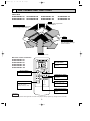
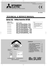
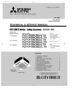
SPLIT-TYPE, HEAT PUMP AIR CONDITIONERS
July 2007
No. OC320
REVISED EDITION-B
TECHNICAL & SERVICE MANUAL
Indoor unit
[Model names]
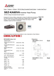
SLZ-KA25VA
SLZ-KA35VA
SLZ-KA50VA
SLZ-KA25VAL
SLZ-KA35VAL
SLZ-KA50VAL
Revision:
• SLZ-KA25/35/50VA(L)1.TH
are added in REVISED
EDITION-B.
• Some descriptions have
been modified.
[Service Ref.]
SLZ-KA25VA.TH
SLZ-KA25VA1.TH
SLZ-KA35VA.TH
SLZ-KA35VA1.TH
SLZ-KA50VA.TH
SLZ-KA50VA1.TH
SLZ-KA25VAL.TH
SLZ-KA25VAL1.TH
SLZ-KA35VAL.TH
SLZ-KA35VAL1.TH
SLZ-KA50VAL.TH
SLZ-KA50VAL1.TH
•Please void OC320 REVISED
EDITION-A.
Note:
• This manual describes only
service data of the indoor
units. When servicing outdoor units, please refer to
the service manual
No.OC322 or OC323
together with this manual.
• RoHS compliant products
have <G> mark on the spec
name plate.
• For servicing RoHS
compliant products, refer
to the RoHS Parts List.
CONTENTS
Model name
indication
ON/OFF
TOO
WARM
TOO
COOL
FAN
SELECT
VANE
TIME
AUTO COOL
HEAT DRY
INDOOR UNIT
TEMP.
ON/OFF
MODE
RESET
SLZ-KA25,35,50VAL.TH
SLZ-KA25,35,50VA.TH
SLZ-KA25,35,50VAL1.TH
SLZ-KA25,35,50VA1.TH
REMOTE CONTROLLER
1. TECHNICAL CHANGES ······················2
2. PART NAMES AND FUNCTIONS ·······3
3. SPECIFICATIONS ································6
4. OUTLINES AND DIMENSIONS ···········8
5. WIRING DIAGRAM ····························11
6. REFRIGERANT SYSTEM DIAGRAM······12
7. TROUBLESHOOTING ·······················13
8. 4-WAY AIR FLOW SYSTEM ··············25
9. DISASSEMBLY PROCEDURE ··········27
10. PARTS LIST ·······································30
11. RoHS PARTS LIST ····························34
OC320B-1.qxp
1
07.7.19 8:45 AM
Page 2
TECHNICAL CHANGES
SLZ-KA25VAL.TH
SLZ-KA35VAL.TH
SLZ-KA50VAL.TH
SLZ-KA25VA.TH
SLZ-KA35VA.TH
SLZ-KA50VA.TH
➔
➔
➔
➔
➔
➔
• PANEL has been changed.
SLP-2AL
➔
SLP-2AA
➔
(White : 0.70Y 8.59/0.97) ➔
SLZ-KA25VAL1.TH
SLZ-KA35VAL1.TH
SLZ-KA50VAL1.TH
SLZ-KA25VA1.TH
SLZ-KA35VA1.TH
SLZ-KA50VA1.TH
SLP-2ALW
SLP-2AAW
(Pure white : 6.4Y 8.9/0.4)
2
OC320B-1.qxp
07.7.19 8:45 AM
2
Page 3
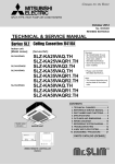
PART NAMES AND FUNCTIONS
Indoor Unit
SLZ-KA25VAL.TH
SLZ-KA35VAL.TH
SLZ-KA50VAL.TH
SLZ-KA25VA.TH
SLZ-KA35VA.TH
SLZ-KA50VA.TH
SLZ-KA25VAL1.TH
SLZ-KA35VAL1.TH
SLZ-KA50VAL1.TH
SLZ-KA25VA1.TH
SLZ-KA35VA1.TH
SLZ-KA50VA1.TH
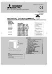
Filter
Removes dust and pollutants
from inhaled air.
Horizontal Air Outlet
Sets horizontal airflow automatically
during cooling or dehumidifying.
Grille
Auto Air Swing Vane
Disperses airflow up and
down and adjusts the angle
of airflow direction.
Air Intake
Inhales air from room.
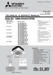
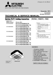
Wireless remote comtroller
SLZ-KA25VAL.TH
SLZ-KA35VAL.TH
SLZ-KA50VAL.TH
SLZ-KA25VAL1.TH
SLZ-KA35VAL1.TH
SLZ-KA50VAL1.TH
TEMPERATURE
SETTING button
h
ON/OFF
TOO
WARM
TOO
COOL
FAN
SELECT
To set any desired room
temperature.
ON / OFF button
To start and to stop operation.
AUTO COOL
HEAT DRY
TIMER SELECT button
VANE
TIME
MODE
To set time to start or stop
unit operation.
FAN SPEED button
MODE SELECT button
To change the operation
mode; Auto, Cooling ,
Heating and Drying . (SLZ)
RESET
To set fan speed to Low,
Medium or High.
VANE CONTROL button
To change the airflow
direction.
Attention:
• Avoid pushing buttons with fingernails and other sharp objects. Sharp objects may damage remote controller.
3
OC320B-1.qxp
07.7.19 8:45 AM
Page 4
● Wired remote controller
Once the controllers are set, the same operation mode can be repeated by simply pressing the ON/OFF button.
SLZ-KA25VA.TH
SLZ-KA35VA.TH
SLZ-KA50VA.TH
SLZ-KA25VA1.TH
SLZ-KA35VA1.TH
SLZ-KA50VA1.TH
ON/OFF button
Temperature setting buttons
Down
Fan Speed button
Up
Timer Menu button
(Monitor/Set button)
Filter
button
(<Enter> button)
Mode button (Return button)
TEMP.
ON/OFF
Set Time buttons
Check button (Clear button)
Back
Ahead
Test Run button
MENU
BACK
MONITOR/SET
ON/OFF
FILTER
DAY
CHECK TEST
Airflow Up/Down button
Timer On/Off button
(Set Day button)
PAR-21MAA
OPERATION
CLOCK
CLEAR
Louver button
(
Operation button)
To return operation
number
Opening the
lid
Ventilation button
( Operation button)
Built-in temperature sensor
4
To go to next operation
number
OC320B-1.qxp
07.7.19 8:45 AM
Page 5
● Wired remote controller
Display Section
For purposes of this explanation,
all parts of the display are shown
as lit. During actual operation, only
the relevant items will be lit.
Day-of-Week
“Sensor” indication
Shows the current day of the week.
Displayed when the remote controller
sensor is used.
Time/Timer Display
Shows the current time, unless the simple or Auto Off
timer is set.
If the simple or Auto Off timer is set, the time to be
switched off is shown.
“Locked” indicator
Indicates that remote controller buttons have been locked.
Identifies the current operation
“Clean The Filter” indicator
Shows the operating mode, etc.
*Multilanguage display is available.
To be displayed on when it is time to
clean the filter.
TIME SUN MON TUE WED THU FRI SAT
TIMER
Hr
ON
AFTER
AFTER OFF
ERROR CODE
FUNCTION
FILTER
˚F˚C
“Centrally Controlled” indicator
Indicates that operation from the
remote controller has been prohibited by a master controller.
˚F˚C
WEEKLY
SIMPLE
AUTO OFF
ONLY1Hr.
Timer indicators
The indicator comes on if the corresponding timer is set.
Fan Speed indicator
Shows the selected fan speed.
“Timer is Off” indicator
Indicates that the timer is off.
Up/Down Air Direction indicator
Shows the direction of the
outcoming airflow.
Room Temperature display
Shows the room temperature. The room
temperature display range is 8~39:.
The display blinks if the temperature
is less than 8: or 39: or more.
Ventilation indicator
Appears when the unit is running in
Ventilation mode.
“One Hour Only” indicator
Temperature Setting
Shows the target temperature.
Displayed if the airflow is set to
low or downward during COOL
or DRY mode. (Operation varies
according to model.)
The indicator goes off in one hour,
when the airflow direction also
changes.
Louver display
Indicates the action of the swing louver.
Does not appear if the louver is not
running.
(Power On indicator)
Indicates that the power is on.
Note:
● “PLEASE WAIT” message
This message is displayed for approximately 3 minutes when power is supplied to the indoor unit or when the unit is recovering from a power failure.
● “NOT AVAILABLE” message
This message is displayed if an invalid button is pressed (to operate a function that the indoor unit does not have).
If a single remote controller is used to operate multiple indoor units simultaneously that are different types, this message will not be displayed as
far as any of the indoor units is equipped with the function.
5
OC320B-1.qxp
3
07.7.19 8:45 AM
Page 6
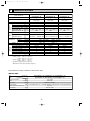
SPECIFICATIONS
Indoor service ref.
Function
Power supply
Fan
motor
Electrical
data
Capacity Air flow (High/Medium/Low)
Power outlet
Running current ✽1
Power input Rated frequency
Dew prevention heater
Power factor ✽1
Fan motor current ✽1
Model
Winding
resistance (at 26:)
Special
remarks
Dimensions
K /h
A
A
W
(kW)
%
A
"
Width
Height
Depth
Weight
Air direction
Sound level(High/Medium/Low)
Fan speed(High/Medium/Low)
Fan speed regulator
Thermistor TH1(at25:)
Thermistor TH2(at25:)
Thermistor TH5(at25:)
SLZ-KA25VAL(1).TH
SLZ-KA25VA(1).TH
Cooling
Heating
Single phase
230V, 50Hz
600/540/480
10
0.35
75
0.014
90
93
0.19
PK6V15-LD
WHT-BLK : 407
BLU-YLW : 30
mm(in)
mm(in)
mm(in)
kg
dB(A)
rpm
k"
k"
k"
SLZ-KA35VAL(1).TH
SLZ-KA35VA(1).TH
Cooling
Heating
Single phase
230V, 50Hz
660/540/480
10
0.40
85
0.014
94
94
0.26
PK6V20-LL
SLZ-KA50VAL(1).TH
SLZ-KA50VA(1).TH
Cooling
Heating
Single phase
230V, 50Hz
660/540/480
20
0.65
85
0.014
97
97
0.27
PK6V20-LM
BLK-BLU : 86 WHT-BLK : 393 BLK-BLU : 164 WHT-BLK : 325 BLK-BLU : 143
BRN-RED : 165 BLU-YLW : 47 BRN-RED : 319 BLU-YLW : 47 BRN-RED : 309
UNIT : 570(22-7/16)
UNIT : 208(8-3/16)
UNIT : 570(22-7/16)
UNIT : 16.5
4
37/31/28
650/530/480
3
10
10
10
PANEL : 650(25-9/16)
PANEL : 20(13/16)
PANEL : 650(25-9/16)
PANEL : 3
4
38/33/29
690/570/510
3
10
10
10
4
39/34/30
710/590/530
3
10
10
10
NOTE : Test conditions are based on ISO 5151.
Cooling : Indoor D.B. 27: W.B. 19:
Outdoor D.B. 35: W.B. 24:
Heating : Indoor D.B. 20: W.B. 15:
Outdoor D.B. 7: W.B. 6:
Refrigerant piping length (one way): 5m
✽1 Measured under rated operating frequency
Specifications and rating conditions of main electric parts
INDOOR UNIT
Service ref.
Item
SLZ-KA25VA(1).TH SLZ-KA35VA(1).TH SLZ-KA50VA(1).TH
Indoor fan capacitor
Fuse
SLZ-KA25VAL(1).TH SLZ-KA35VAL(1).TH SLZ-KA50VAL(1).TH
(C1)
1.5+ 440V
(FUSE)
250V 6.3A
Vane motor
(MV)
Terminal block
(TB) TO OUTDOOR UNIT : 3P TO WIRED REMOTE CONTROLLER : 2P (SLZ-KA25/35/50VA)
MSBPC20 12V 250"
Indoor fan motor thermal fuse
Cord Heater
141:i3:
(H2)
240V AC 15W
6
OC320B-1.qxp
07.7.19 8:45 AM
Page 7
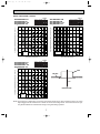
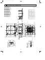
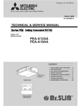
NOISE CRITERION CURVES
<50Hz>
<50Hz>
SLZ-KA25VAL.TH
SLZ-KA25VA.TH
SLZ-KA25VAL1.TH
SLZ-KA25VA1.TH
NOTCH SPL(dB)
High
37
Medium
31
Low
28
SLZ-KA35VAL.TH
SLZ-KA35VA.TH
SLZ-KA35VAL1.TH
SLZ-KA35VA1.TH
LINE
LINE
90
80
70
NC-70
60
NC-60
50
NC-50
40
NC-40
30
NC-30
APPROXIMATE
TERESHOLD OF
HEARING FOR
CONTINUOUS
NOISE
20
NC-20
OCTAVE BAND SOUND PRESSURE LEVEL, dB (0 dB = 0.0002 µbar)
90
OCTAVE BAND SOUND PRESSURE LEVEL, dB (0 dB = 0.0002 µbar)
NOTCH SPL(dB)
High
38
Medium
33
Low
29
80
70
NC-70
60
NC-60
50
NC-50
40
NC-40
30
NC-30
20
APPROXIMATE
TERESHOLD OF
HEARING FOR
CONTINUOUS
NOISE
NC-20
10
10
63
125
250
500
1000
2000
4000
63
8000
125
250
500
1000
2000
4000
8000
BAND CENTER FREQUENCIES, Hz
BAND CENTER FREQUENCIES, Hz
<50Hz>
SLZ-KA50VAL.TH
SLZ-KA50VA.TH
SLZ-KA50VAL1.TH
SLZ-KA50VA1.TH
NOTCH SPL(dB)
High
39
Medium
34
Low
30
LINE
OCTAVE BAND SOUND PRESSURE LEVEL, dB (0 dB = 0.0002 µbar)
90
UNIT
80
CEILING
70
NC-70
60
NC-60
1.5m
50
NC-50
40
NC-40
MICROPHONE
30
NC-30
20
APPROXIMATE
TERESHOLD OF
HEARING FOR
CONTINUOUS
NOISE
NC-20
10
63
125
250
500
1000
2000
4000
8000
BAND CENTER FREQUENCIES, Hz
NOTE: The sound level is measured in an anechoic room where echoes are few, when compressor stops. The sound
may be bigger than the indicated level in actual use due to surrounding echoes. The sound level can be higher by about 2 dB than the indicated level during cooling and heating operation.
7
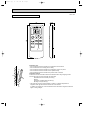
{ 100
118
{ 73.4
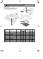
Cut out hole
Refrigerent pipe (liquid)
Emergency operation switch(heating)
Emergency operation switch(cooling)
Receiver
420
Suspension bolt pitch
Refrigerent pipe (gas)
17
202
230
35 55
V/M
V/M
377
Air intake hole
Grille
Terminal block
(Case of Wired remote controller)Terminal block
650
301
Air outlet hole
15~37
199
352
335
576~620 Ceiling hole
570
530
Suspension bolt
pitch
V/M
V/M
Ceiling surface
15~37
570
Brand label
Vane motor
Air intake grille
Auto vane
Drain hole
Grille
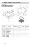
SLZ-KA50VA(L)
{ 12.7mm
flared connection
1/2 inch
{ 9.52mm
flared connection
3/8 inch
{ 6.35mm
SLZ-KA35VA(L) flared connection
1/4 inch
{ 6.35mm
flared connection
1/4 inch
{ 9.52mm
flared connection
3/8 inch
{ 6.35mm
flared connection
1/4 inch
SLZ-KA25VA(L)
Refrigerent pipe
(gas)
Models
Refrigerent pipe
(liquid)
Wiring entry
Suspension bolt
M10 or 3/8
(procure locally)
Drain pipe
VP-25 connection
(O.D. { 32)
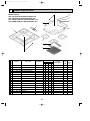
SLZ-KA25VAL.TH
SLZ-KA35VAL.TH
SLZ-KA50VAL.TH
SLZ-KA25VA.TH
SLZ-KA35VA.TH
SLZ-KA50VA.TH
SLZ-KA25VAL1.TH
SLZ-KA35VAL1.TH
SLZ-KA50VAL1.TH
SLZ-KA25VA1.TH
SLZ-KA35VA1.TH
SLZ-KA50VA1.TH
DEFROST/STAND BY lamp
Operation lamp
(WIRELESS PANEL)
Ceiling surface
25
66
121
3- { 2.8 hole
Burring hole
93
Detail drawing of fresh air intake
12
0°
15~37
576~620 Ceiling hole
15~37
Fresh air
intake
193
57
56
38~58
55 35 Suspension bolt
lower edge
650
8
301
Air outlet hole
335
31
208
+5
27 0
87
235
20
0°
12
377
Air intake hole
4
182
07.7.19 8:45 AM
48
OC320B-1.qxp
Page 8
OUTLINES AND DIMENSIONS
Unit : mm
OC320B-1.qxp
07.7.19 8:45 AM
Page 9
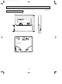
Unit : mm
WIRELESS REMOTE CONTROLLER
57
17.5
h
140
ON/OFF
TOO
WARM
TOO
COOL
FAN
SELECT
VANE
TIME
AUTO COOL
HEAT DRY
MODE
RESET
D
B
A
C
Installation area
• Area in which the remote controller is not exposed to direct sunshine
• Area in which there is no heating source nearby
• Area in which the remote controller is not exposed to cold (or hot) winds
• Area in which the remote controller can be operated easily
• Area in which the remote controller is beyond the reach of children
Installation method
1 Attach the remote controller holder to the desired location using 2 tapping screws.
2 Insert the lower end of the controller into the holder.
A Wireless remote controller (Accessory)
B Wall
C Remote controller holder (Accessory)
D Fixing screw (Accessory)
• The signal can travel up to approximately 7 meters (in a straight line) within 45
degrees to both right and left of the center line of the receiver.
In addition, the signal may not be received if there is interference of light of fluorescent
lights or strong sunlight.
9
OC320B-1.qxp
07.7.19 8:45 AM
Page 10
Unit : mm
WIRED REMOTE CONTROLLER
43.5
120
130
19
10
OC320B-1.qxp
07.7.19 8:45 AM
5
Page 11
WIRING DIAGRAM
SLZ-KA25VAL.TH SLZ-KA25VA.TH
SLZ-KA35VAL.TH SLZ-KA35VA.TH
SLZ-KA50VAL.TH SLZ-KA50VA.TH
SLZ-KA25VAL1.TH SLZ-KA25VA1.TH
SLZ-KA35VAL1.TH SLZ-KA35VA1.TH
SLZ-KA50VAL1.TH SLZ-KA50VA1.TH
GRILLE
TB4
S1
S2
MV
BLU
TO OUTDOOR UNIT
S3
1
5
WHT
2
MV
YLW
3
DP
P.B
2 3
ORN
W.B
GRY
7
PINK
8
5
7
1
1
X1
RED
3 (POWER
1
BOARD)
CNDK
FUSE
ORN
3 (POWER)
CND
1
BLU
ORN
BLU
RED
WHT
RED
YLW
BLU
3 (D·U·M)
CNP
I.B
TRANS
3
BLU
(CONTROL)
CN3C
DC13.1V
1 2 CN2S(WHT)
X6 X5 X4
ZNR
X7
9
LED2
VLT
6
BZ
3
RED
3 (D·HEATER) 1
CNC
5
BLU
CNB
1
1 2 3 AC220-240V
CNSK(RED)
4
YLW
9
WHT
9 (FAN)
FAN
2
YLW
YLW
1
RED
YLW
RED
BLU
9
C1
BRN
WHT
H2
1
ORN
BLK
YLW
YLW
5
YLW
MV
MF
5 10 8
RED
7 4
5
6
ORN
5
BRN
5
MV
SKY BLU
X6 X5 X4
LED1
X7
SW1
SW2
<fig:w1>
LED1
CN2L
ON
OFF
GRN
(VANE)
CN6V
CN41
1
2
3
4
5
RED
CN51
BLU
CN32
WHT
12345
YLW
ORN
RU
WHT
LED3
12345
SW2
BLK
WHT
(POWER 1
BOARD)
2
CN2D
X1
SW3
SWE
ON
ON
OFF
OFF
CN90
(WIRELESS)
WHT
6
1
2
REMOTE
CONTROLLER
3
4
5
6
WHT
(DRAIN)
CN31
7
8
9
1
2
BLK
RED
(2 PHASE) (INTAKE)
CN20
CN29
1
2
1
2
3
MODELS
LED2
SW2
KA25
ON
OFF
KA35
ON
OFF
KA50
ON
OFF
1 2 3 4 5
WHT
(LIQUID)
CN21
1
BLU
(REMOCON)
CN22
2
1
1 2 3 4 5
2
BLU
BLU
VLT
GRY
PINK
BLU
RED
5
SKYBLU
See fig:w1
YLW
W.R
ORN
BRN
1 2 3 4 5
* Case of wired model
9
TB15
1
2
DS
TH5
TH1
TH2
TO MA-REMOTE
} CONTROLLER
DC8.7-13V
* Case of wireress model
[LEGEND]
SYMBOL
NAME
INDOOR POWER BOARD
P.B
I.B
SYMBOL
W.B
NAME
WIRELESS REMOTE CONTROLLER BOARD
INDOOR CONTROLLER BOARD
RU
RECEIVING UNIT
CN2L
CONNECTOR(LOSSNAY)
BZ
BUZZER
CN32
CONNECTOR(REMOTE SWITCH)
LED1
LED(RUN INDICATOR)
CN41
CONNECTOR(HA TERMINAL-A)
LED2
LED(HOT ADJUST)
CN51
CENTRALLY CONTROL
SW1
SWITCH(HEATING ON/OFF)
FUSE
FUSE(T6.3AL250V)
SW2
SWITCH(COOLING ON/OFF)
LED1
POWER SUPPLY(I.B)
C1
CAPACITOR(FAN MOTOR)
LED2
POWER SUPPLY(I.B)
DP
DRAIN PUMP
LED3
TRANSMISSION(INDOOR-OUTDOOR)
DS
DRAIN SENSOR
SW2
SWITCH(CAPACITY CODE)
H2
DEW PREVENTION HEATER
SW3
SWITCH(MODE SELECTION)
MF
FAN MOTOR
SWE
SWITCH(EMERGENCY OPERATION)
X1
DRAIN PUMP/DEW PREVENTION HEATER
X4
RELAY(FAN MOTOR LL)
X5
RELAY(FAN MOTOR Lo)
X6
RELAY(FAN MOTOR Hi)
X7
RELAY(FAN MOTOR Me)
ZNR
VARISTOR
MV
TB4
TB15
TH1
TH2
TH5
VANE MOTOR
TERMINAL BLOCK(INDOOR/OUTDOOR CONNECTING LINE)
TERMINAL BLOCK(REMOTE CONTROLLER
TRANSMISSION LINE)
ROOM TEMP.THERMISTOR
(0°C/15kΩ, 25°C/5.4kΩ DETECT)
PIPE TEMP.THERMISTOR/LIQUID
(0°C/15kΩ, 25°C/5.4kΩ DETECT)
COND./EVA.TEMP.THERMISTOR
(0°C/15kΩ, 25°C/5.4kΩ DETECT)
NOTES : 1. Since the outdoor side electric wiring may change, be sure to check the outdoor unit electric wiring for servicing.
2. Indoor and outdoor connecting wires have polarities, make sure to match terminal numbers(S1,S2,S3) for correct wiring.
3. Symbols used in wiring diagram above are,
: Connector,
: Terminal (block).
w For details on how to operate self-diagnosis, refer to the technical manuals etc.
11
OC320B-1.qxp
6
07.7.19 8:45 AM
Page 12
REFRIGERANT SYSTEM DIAGRAM
SLZ-KA25VAL.TH
SLZ-KA35VAL.TH
SLZ-KA50VAL.TH
SLZ-KA25VA.TH
SLZ-KA35VA.TH
SLZ-KA50VA.TH
SLZ-KA25VAL1.TH
SLZ-KA35VAL1.TH
SLZ-KA50VAL1.TH
SLZ-KA25VA1.TH
SLZ-KA35VA1.TH
SLZ-KA50VA1.TH
Strainer
#50
Heat exchanger
Refrigerant GAS pipe connection
(Flare)
Condenser/evaporator
temperature thermistor
(TH5)
Refrigerant flow in cooling
Refrigerant flow in heating
Refrigerant LIQUID pipe connection
(Flare)
Pipe temperature
thermistor/liquid
(TH2)
Room temperature
thermistor (TH1)
Distributor
with strainer
#50
Strainer
#50
12
OC320B-1.qxp
07.7.19 8:45 AM
7
Page 13
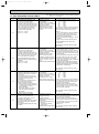
TROUBLESHOOTING
7-1. CAUTIONS ON TROUBLESHOOTING
(1) Before troubleshooting, check the followings:
1Check the power supply voltage.
2Check that the indoor/outdoor connecting wire is correct.
(2) Take care of the followings during servicing.
1 Before servicing the air conditioner, be sure to turn off the remote controller first to stop the main unit, and then turn
off the breaker.
2 When removing the indoor controller board, hold the edge of the board with care NOT to apply stress on the
components.
3 When connecting or disconnecting the connectors, hold the housing of the connector. DO NOT pull the lead wires.
Lead wire
7-2. SELF-CHECK
7-2-1. Wired remote controller
B
1 Turn on the power.
2 Press the [CHECK] button twice.
3 Set address with [TEMP] button if system control is used.
4 Press the [ON/OFF] button to stop the self-check.
E D
A CHECK button
B Address
C TEMP. button
D IC : Indoor unit
OC: Outdoor unit
– – – – : No trouble generated in the past.
E Check code
F F F F : No corresponding unit.
F Unit No.
ERROR CODE
ERROR CODE
TEMP.
C
MENU
BACK
MONITOR/SET
ON/OFF
ON/OFF
E
B
FILTER
DAY
CHECK TEST
ERROR CODE
PAR-21MAA
OPERATION
CLOCK
G Timer ON/OFF button
CLEAR
<To delete check code>
F
G
1 Display the error code on the self-check result display screen.
2 The address for self-check will blink when the G
ON/OFF
button is pressed twice within 3 seconds.
A
7-2-2. Wireless remote controller
h
ON/OFF
TOO
WARM
TOO
COOL
FAN
SELECT
VANE
TIME
56
24
AUTO COOL
HEAT DRY
MODE
24
RESET
23
[Procedure]
1 Turn ON the power.
2 While pressing both the MODE SELECT button and
TOO COOL button on the remote controller at the same
time, press the RESET button.
3 Firstly, release the RESET button.
4 And release the other 2 buttons since all LCD in
operation display section of the remote controller is
displayed after 3 seconds.
5 Transmit the signal of remote controller, pressing ON/ OFF
button on the remote controller.
(The above procedure allows OPERATION INDICATOR lamp
to indicate the failure-mode.)
6 Transmit the signal of remote controller, pressing ON/ OFF
button to stop the self-check.
OPERATION INDICATER
13
OC320B-1.qxp
07.7.19 8:45 AM
Page 14
• Refer to the following tables for details on the check codes.
[Output pattern A]
Beeper sounds
OPERATION
INDICATOR
lamp blink
pattern
Beep
Beep Beep Beep
Off
Beep
1st
2 nd
3 rd
nth
On
On
On
On
Beep Beep
1st
Off
On
2 nd · · · Repeated
On
0.5 sec. Approx. 2.5 sec. 0.5 sec. 0.5 sec.
Self-check Approx. 2.5 sec. 0.5 sec. 0.5 sec. 0.5 sec.
starts
(Start signal
Number of blinks/beeps in pattern indicates the check
Number of blinks/beeps in pattern indicates
received)
code in the following table (i.e., n=5 for “P5”)
the check code in the following table
[Output pattern B]
Beeper sounds
OPERATION
INDICATOR
lamp blink
pattern
Beep
Beep Beep Beep
1st
Off
On
Approx. 3 sec.
Self-check Approx. 2.5 sec.
starts
(Start signal
received)
2nd
3 rd
On
On
On
0.5 sec. 0.5 sec. 0.5 sec.
Beep
Beep
nth
1st
On
Off
0.5 sec. Approx. 2.5 sec.
Number of blinks/beeps in pattern indicates the check
code in the following table (i.e., n=5 for “U2”)
On
Approx. 3 sec.
Beep
2 nd · · · Repeated
On
On
0.5 sec. 0.5 sec.
Number of blinks/beeps in pattern indicates
the check code in the following table
[Output pattern A] Errors detected by indoor unit
Wireless remote controller Wired remote controller
Beeper sounds/OPERATION
INDICATOR lamp blinks
1 Check code
(Number of times)
1
P1
P2
2
P9
3
E6,E7
4
P4
5
P5
6
P6
7
EE
8
P8
9
E4, E5
–
10
–
11
12
Fb
E0, E3
–
–
E1, E2
Symptom
Remark
Intake sensor error
Pipe (TH2) sensor error
Pipe (TH5) sensor error
Indoor/outdoor unit communication error
Drain sensor error
Drain pump error
Freezing/Overheating protection operation
Communication error between indoor and outdoor units
Pipe temperature error
Remote controller signal receiving error
–
–
Indoor unit control system error (memory error, etc.)
Remote controller transmission error
Remote controller control board error
[Output pattern B] Errors detected by unit other than indoor unit (outdoor unit, etc.)
Wireless remote controller Wired remote controller
Beeper sounds/OPERATION
INDICATOR lamp blinks
1 Check code
(Number of times)
1
E9
2
3
4
UP
U3,U4
UF
5
U2
6
U1,Ud
7
8
9
10
U5
U8
U6
U7
11
U9,UH
Symptom
Indoor/outdoor unit communication error
(Transmitting error) (Outdoor unit)
Compressor overcurrent interruption
Open/short of outdoor unit thermistors
Compressor overcurrent interruption (When compressor locked)
Abnormal high discharging temperature/49C worked/
insufficient refrigerant
Abnormal high pressure (63H worked)/Overheating
protection operation
Abnormal temperature of heatsink
Outdoor unit fan protection stop
Compressor overcurrent interruption/Abnormal of power module
Abnormality of superheat due to low discharge temperature
Abnormality such as overvoltage or voltage shortage and
abnormal synchronous signal to main circuit/Current sensor error
–
–
Other errors (Refer to the technical manual for the outdoor unit.)
Remark
For details, check
the LED display
of the outdoor
controller board.
As for outdoor
unit, refer to
service manual
OC322 or
OC323.
–
12
–
13
Others
14
*1 If the beeper does not sound again after the initial 2 beeps to confirm the self-check start signal was received and
the OPERATION INDICATOR lamp does not come on, there are no error records.
*2 If the beeper sounds 3 times continuously “beep, beep, beep (0.4 + 0.4 + 0.4 sec.)” after the initial 2 beeps to confirm
the self-check start signal was received, the specified refrigerant address is incorrect.
continued to the next page.
14
OC320B-1.qxp
07.7.19 8:45 AM
Page 15
• On wireless remote controller
2The continuous buzzer sounds from receiving section of indoor unit.
3Blink of operation lamp
• On wired remote controller
1Check code displayed on the LCD.
• If the unit cannot be operated properly after the test run, refer to the following table to find out the cause.
Symptom
Cause
Wired remote controller
PLEASE WAIT
PLEASE WAIT → Error code
For about 2 minutes after power-on
Subsequent to about 2 minutes
after power-on
No messages appear even
when operation switch is turned
ON (operation lamp does not
light up).
•For about 2 minutes after power-on,operation of the
remote controller is not possible due to system start-up.
(Correct operation)
•Connector for the outdoor unit’s protection device is not
connected.
•Reverse or open phase wiring for the outdoor unit’s
power terminal block
•Incorrect wiring between indoor and outdoor units.
(incorrect polarity of S1, S2, S3)
•Remote controller wire short
On the wireless remote controller with condition above, following phenomena take place.
• No signals from the remote controller can be received.
• Operation lamp is blinking.
• The buzzer makes a short ping sound.
Note:
Operation is not possible for about 30 seconds after cancellation of function selection. (Correct operation)
For description of each LED (LED1, 2, 3) provided on the indoor controller, refer to the following table.
LED2 (power for remote controller)
Indicates whether control power is supplied. Make sure that this LED is
always lit.
Indicates whether power is supplied to the remote controller.
This LED lights only in the case of the indoor unit which is connected to the
outdoor unit refrigerant address “0”.
LED3 (communication between indoor and
outdoor units)
Indicates state of communication between the indoor and outdoor units.
Make sure that this LED is always blinking.
LED1 (power for microcomputer)
15
OC320B-1.qxp
07.7.19 8:45 AM
Page 16
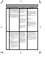
7-3. SELF-DIAGNOSIS ACTION TABLE
Error Code
P1
Abnormal point and detection method
Room temperature thermistor (TH1)
1 The unit is in 3-minute resume
prevention mode if short/open of
thermistor is detected. Abnormal if the
unit does not reset normally after 3 minutes. (The unit returns to normal operation, if it has been reset normally.)
2 Constantly detected during cooling,
drying and heating operation
Short: 90: or more
Open: -40: or less
Note: Refer to the manual of outdoor unit for the details of display
such as F, U, and other E.
Cause
1 Defective thermistor
characteristics
2 Contact failure of connector
(CN20) on the indoor controller
board (Insert failure)
3 Breaking of wire or contact
failure of thermistor wiring
4 Defective indoor controller
board
Countermeasure
1–3 Check resistance value of thermistor.
0: ····15.0k"
10: ······9.6k"
20: ······6.3k"
30: ······4.3k"
40: ······3.0k"
If you put force on (draw or bend) the lead wire
with measuring resistance value of thermistor,
breaking of wire or contact failure can be
detected.
2 Check contact failure of connector (CN20) on
the indoor controller board. Refer to 7-5.
Turn the power back on and check restart
after inserting connector again.
4 Check room temperature display on remote
controller.
Replace indoor controller board if there is
abnormal difference with actual room
temperature.
Turn the power off, and on again to operate
after checking.
P2
Pipe temperature thermistor/Liquid
(TH2)
1 The unit is in 3-minute resume
prevention mode if short/open of
thermistor is detected. Abnormal if the
unit does not reset normally after 3 minutes. (The unit returns to normal operation, if it has been reset normally.)
2 Constantly detected during cooling,
drying, and heating (except defrosting)
operation.
Short: 90: or more
Open: -40: or less
1 Defective thermistor
characteristics
2 Contact failure of connector
(CN21) on the indoor controller
board (Insert failure)
3 Breaking of wire or contact
failure of thermistor wiring
4 Defective refrigerant circuit is
causing thermistor temperature
of 90: or more or -40: or
less.
5 Defective indoor controller board
1–3 Check resistance value of thermistor.
For characteristics, refer to (P1) above.
2 Check contact failure of connector (CN21) on
the indoor controller board. Refer to 7-5. Turn
the power on and check restart after inserting
connector again.
4 Check pipe <liquid> temperature with remote
controller in test run mode. If pipe <liquid>
temperature is extremely low (in cooling
mode) or high (in heating mode), refrigerant
circuit may have defect.
5 Check pipe <liquid> temperature with remote
controller in test run mode. If there is extreme
difference with actual pipe <liquid> temperature,
replace indoor controller board.
Turn the power off, and on again to operate
after checking.
P4
P5
Drain sensor (DS)
1 Suspensive abnormality, if short/open of
thermistor is detected for 30 seconds
continuously.
Turn off compressor and indoor fan.
2 Short/open is detected for 30 seconds
continuously during suspensive
abnormality.
(The unit returns to normal operation,
if it has been reset normally.)
3 Detect the following condition.
• During cooling and drying operation
• In case that pipe <liquid> temperature
- room temperature <-10deg
(Except defrosting)
• When pipe <liquid> temperature or
room temperature is short/open
temperature.
• During drain pump operation
1 Defective thermistor
1–3 Check resistance value of thermistor.
characteristics
0: ······6.0k"
2 Contact failure of connector
10: ······3.9k"
(CN31) on the indoor controller
20: ······2.6k"
board (Insert failure)
30: ······1.8k"
3 Breaking of wire or contact
40: ······1.3k"
failure of drain sensor wiring
2 Check contact failure of connector (CN31) on
4 Defective indoor controller board
the indoor controller board. Refer to 7-5. Turn
the power back on and check restart after
inserting connector again.
4 Replace indoor controller board if drain
pump operates with the line of drain sensor
connector CN31-1 and 2 is short-circuited,
and abnormality reappears.
Malfunction of drain pump (DP)
1 Suspensive abnormality, if thermistor
of drain sensor heats itself and
temperature rises slightly. Turn off
compressor and indoor fan.
2 Drain pomp is abnormal if the condition
above is detected during suspensive
abnormality.
3 Constantly detected during drain pump
operation
1 Malfunction of drain pump
2 Defective drain
Clogged drain pump
Clogged drain pipe
3 Attached drop of water at the
drain sensor
• Drops of drain trickles from
lead wire
• Clogged filter is causing
wave of drain.
4 Defective indoor controller board
Turn the power off, and on again to operate
after checking.
16
1 Check if drain pump works.
2 Check drain function.
3 Check the setting of lead wire of drain sensor
and check clogs of the filter.
4 Replace indoor controller board if drain
pump operates with the line of drain sensor
connector CN31-1 and 2 is short-circuited
and abnormality reappears.
Refer to 7-5.
Turn the power off, and on again to operate
after checking.
OC320B-1.qxp
07.7.19 8:45 AM
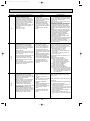
Error Code
Page 17
Abnormal point and detection method
Cause
Freezing/overheating protection is
working
1 Freezing protection (Cooling mode)
The unit is in 6-minute resume prevention
mode if pipe <liquid or condenser/evaporator> temperature stays under
-15: for 3 minutes after the compressor started. Abnormal if it stays under 15: for 3 minutes again within 16 minutes after 6-minute resume prevention
mode.
(Cooling or drying mode)
1 Clogged filter (reduced airflow)
2 Short cycle of air path
3 Low-load (low temperature)
operation out of the tolerance
range
4 Defective indoor fan motor
• Fan motor is defective.
• Indoor controller board is
defective.
2 Overheating protection (Heating mode)
The units is in 6-minute resume
prevention mode if pipe <condenser /
5 Defective outdoor fan control
evaporator> temperature is detected as 6 Overcharge of refrigerant
over 70: after the compressor started. 7 Defective refrigerant circuit
Abnormal if the temperature of over
(clogging)
70: is detected again within 10 minutes
after 6-minute resume prevention mode.
(Heating mode)
1 Clogged filter (reduced airflow)
2 Short cycle of air path
3 Overload (high temperature)
operation out of the tolerance
range
4 Defective indoor fan motor
• Fan motor is defective.
• Indoor controller board is
defective.
P6
5 Defective outdoor fan control
6 Overcharge of refrigerant
7 Defective refrigerant circuit
(clogging)
8 Bypass circuit of outdoor unit
is defective.
P8
Pipe temperature
1 Slight temperature difference
<Cooling mode>
between indoor room
Detected as abnormal when the pipe temtemperature and pipe <liquid
perature is not in the cooling range 3 minor condenser / evaporator>
utes after compressor start and 6 minutes
temperature thermistor
after the liquid or condenser/evaporator pipe
• Shortage of refrigerant
is out of cooling range.
• Disconnected holder of pipe
Note 1) It takes at least 9 min. to detect.
<liquid or condenser /
Note 2) Abnormality P8 is not detected in
evaporator> thermistor
drying mode.
• Defective refrigerant circuit
Cooling range : -3 deg ] (TH-TH1)
2 Converse connection of
TH: Lower temperature between liquid pipe
extension pipe (on plural units
temperature (TH2) and
connection)
condenser/evaporator temperature
3 Converse wiring of indoor/
(TH5)
outdoor unit connecting wire
TH1: Intake temperature
(on plural units connection)
4 Defective detection of indoor
<Heating mode>
room temperature and pipe
When 10 seconds have passed after the
<condenser / evaporator>
compressor starts operation and the hot
temperature thermistor
adjustment mode has finished, the unit is
5 Stop valve is not opened
detected as abnormal when
completely.
condenser/evaporator pipe temperature is
not in heating range within 20 minutes.
Note 3) It takes at least 27 minutes to
detect abnormality.
Note 4) It excludes the period of defrosting
(Detection restarts when defrosting
mode is over)
Heating range : 3 deg [ (TH5-TH1)
17
Countermeasure
(Cooling or drying mode)
1 Check clogging of the filter.
2 Remove shields.
4 Measure the resistance of fan motor's winding.
Measure the output voltage of fan's connector
(FAN) on the indoor controller board.
WThe indoor controller board should be
normal when voltage of AC 220~240V is
detected while fan motor is connected.
Refer to 7-5.
5 Check outdoor fan motor.
67 Check operating condition of refrigerant
circuit.
(Heating mode)
1 Check clogs of the filter.
2 Remove shields.
4 Measure the resistance of fan motor's
winding.
Measure the output voltage of fan's connector
(FAN) on the indoor controller board.
WThe indoor controller board should be
normal when voltage of AC 220~240V is
detected while fan motor is connected.
Refer to 7-5.
5 Check outdoor fan motor.
6~8Check operating condition of refrigerant
circuit.
1~4Check pipe <liquid or condenser /
evaporator> temperature with room
temperature display on remote
controller and outdoor controller circuit
board.
Pipe <liquid or condenser / evaporator>
temperature display is indicated by
setting SW2 of outdoor controller circuit
board as follows.
Conduct temperature check with outdoor
controller circuit board after connecting
‘A-Control Service Tool(PAC-SK52ST)’.
(
)
23Check converse connection of extension
pipe or converse wiring of indoor/outdoor
unit connecting wire.
OC320B-1.qxp
07.7.19 8:45 AM
Page 18
Error Code
Abnormal point and detection method
P9
Pipe temperature thermistor /
Condenser / Evaporator (TH5)
1 The unit is in 3-minute resume protection mode if short/open of thermistor is
detected. Abnormal if the unit does not
get back to normal within 3 minutes.
(The unit returns to normal operation, if
it has been reset normally.)
2 Constantly detected during cooling, drying, and heating operation (except
defrosting)
Short: 90: or more
Open: -40: or less
Countermeasure
Cause
1 Defective thermistor
1–3 Check resistance value of thermistor.
For characteristics, refer to (P1) above.
characteristics
2 Check contact failure of connector (CN29)
2 Contact failure of connector
on the indoor controller board.
(CN29) on the indoor controller
Refer to 7-5.
board (Insert failure)
Turn the power on and check restart after
3 Breaking of wire or contact
inserting connector again.
failure of thermistor wiring
4 Operate in test run mode and check pipe
4 Temperature of thermistor is
<condenser / evaporator> temperature with
90: or more or -40: or less
outdoor controller circuit board. If pipe
caused by defective refrigerant
<condenser / evaporator> temperature is
circuit.
extremely low (in cooling mode) or high (in
heating mode), refrigerant circuit may have
5 Defective indoor controller
defect.
board
5 Operate in test run mode and check pipe
<condenser / evaporator> temperature with
outdoor control circuit board. If there is
extreme difference with actual pipe
<condenser / evaporator> temperature
replace indoor controller board.
There is no abnormality if none of above
comes within the unit.
Turn the power off and on again to operate.
In case of checking pipe temperature
with outdoor controller circuit board,
be sure to connect A-control service
tool (PAC-SK52ST).
(
Remote controller transmission
error(E0)/signal receiving error(E4)
1 Abnormal if main or sub remote controller cannot receive any transmission
normally from indoor unit of refrigerant
address “0” for 3 minutes.
(Error code : E0)
2 Abnormal if sub-remote controller could
not receive for any signal for 2 minutes.
(Error code: E0)
E0
or
E4
E3
or
E5
1 Abnormal if indoor controller board cannot receive normally any data from
remote controller board or from other
indoor controller board for 3 minutes.
(Error code: E4)
2 Indoor controller board cannot receive
any signal from remote controller for 2
minutes. (Error code: E4)
1 Contact failure at transmission
wire of remote controller
2 All remote controllers are set
as “sub” remote controller. In
this case, E0 is displayed on
remote controller, and E4 is
displayed at LED (LED1, LED2)
on the outdoor controller circuit
board.
3 Miswiring of remote controller
4 Defective transmitting/receiving
circuit of remote controller
5 Defective transmitting/receiving
circuit of indoor controller board
of refrigerant address “0”
6 Noise has entered into the
transmission wire of remote
controller.
Remote controller transmission
error(E3)/signal receiving error(E5)
1 Abnormal if remote controller could not
find blank of transmission path for 6 seconds and could not transmit.
(Error code: E3)
2 Remote controller receives transmitted
data at the same time, compares the
data, and when detecting it, judges
different data to be abnormal 30
continuous times. (Error code: E3)
1 2 remote controllers are set as
“main.”
(In case of 2 remote controllers)
2 Remote controller is connected
with 2 indoor units or more.
3 Repetition of refrigerant
address
4 Defective transmitting/receiving
circuit of remote controller
1 Abnormal if indoor controller board could
5
Defective transmitting/receiving
not find blank of transmission path.
circuit of indoor controller
(Error code: E5)
board
2 Indoor controller board receives transmitted data at the same time, compares 6 Noise has entered into transthe data,and when detecting it, judges
mission wire of remote condifferent data to be abnormal 30
troller.
continuous times. (Error code: E5)
18
)
1 Check disconnection or looseness of indoor
unit or transmission wire of remote controller.
2 Set one of the remote controllers “main”,
if there is no problem with the action above.
3 Check wiring of remote controller.
• Total wiring length: max. 500m
(Do not use cablex 3 or more)
• The number of connecting indoor units:
max. 16 units
• The number of connecting remote controller: max. 2 units
When the above-mentioned problem of 1~3
are not seen.
4 Diagnose remote controllers.
a) When “RC OK” is displayed,
remote controllers have no problem.
Turn the power off, and on again to
check. If abnormality generates again,
replace indoor controller board.
b) When “RC NG” is displayed,
replace remote controller.
c) When “RC E3” is displayed,
d) When “ERC 00-06” is displayed,
[ c),d)→Noise may be causing abnormality. ]
∗ If the unit is not normal after replacing
indoor controller board in group control,
indoor controller board of address “0”
may be abnormal.
1 Set a remote controller to main, and the
other to sub.
2 Remote controller is connected with only one
indoor unit.
3 The address changes to a separate setting.
4~6 Diagnose remote controller.
a) When “RC OK”is displayed, remote controllers have no problem.
Turn the power off, and on again to check.
When becoming abnormal again, replace
indoor controller board.
b)When “RC NG” is displayed, replace
remote controller.
c)When “RC E3”or “ERC 00-66” is displayed, noise may be causing abnormality.
OC320B-1.qxp
07.7.19 8:45 AM
Page 19
Error Code
Abnormal point and detection method
E6
Indoor/outdoor unit communication
error (Signal receiving error)
1 Abnormal if indoor controller board
cannot receive any signal normally for 6
minutes after turning the power on.
2 Abnormal if indoor controller board
cannot receive any signal normally for 3
minutes.
3 Consider the unit abnormal under the
following condition: When 2 or more
indoor units are connected to one
outdoor unit, indoor controller board
cannot receive a signal for 3 minutes
from outdoor controller circuit board, a
signal which allows outdoor controller
circuit board to transmit signals.
E7
Indoor/outdoor unit communication
1 Defective transmitting receiving 1-3 Turn the power off, and on again to
error (Transmitting error)
check. If abnormality generates again,
circuit of indoor controller board
Abnormal if “1” receiving is detected 30
replace indoor controller board.
2 Noise has entered into power
times continuously though indoor controller
supply.
board has transmitted “0”.
3 Noise has entered into outdoor
control wire.
Fb
Indoor controller board
Abnormal if data cannot be normally read
from the nonvolatile memory of the indoor
controller board.
E1
or
E2
PA
(2502)
(2500)
Cause
Countermeasure
1 Contact failure, short circuit or, 1 Check disconnection or looseness of indoor/
outdoor unit connecting wire of indoor unit or
miswiring (converse wiring) of
outdoor unit.
indoor/outdoor unit connecting
Check all the units in case of twin indoor
wire
unit system.
2 Defective transmitting/receiving 2-4 Turn the power off, and on again to
circuit of indoor controller board
check. If abnormality generates again,
3 Defective transmitting/receiving
replace indoor controller board or outdoor
circuit of indoor controller board
controller circuit board.
4 Noise has entered into indoor/ ∗ Other indoor controller board may have
defect in case of twin indoor unit system.
outdoor unit connecting wire.
1 Defective indoor controller
board
Remote controller control board
1 Defective remote controller
1 Abnormal if data cannot be normally
read from the nonvolatile memory of the
remote controller control board.
(Error code: E1)
1 Replace indoor controller board.
1 Replace remote controller.
2 Abnormal if the clock function of remote
controller cannot be normally operated.
(Error code: E2)
Forced compressor stop
(due to water leakage abnormality)
1 When the intake temperature subtracted
with liquid pipe temperature is less than
-10:, drain sensor detects whether
it is soaked in the water or not at the interval
of 90 seconds. (Drain pump will start operating
when the drain sensor detects to be
soaked in the water.)
2 The unit has a water leakage abnormality when the following conditions, a) and
b), are satisfied while the above-mentioned detection is performed.
a) The drain sensor detects to be
soaked in the water 10 times in a row.
b) The intake temperature subtracted with
liquid pipe temperature is detected to be
less than -10: for a total of 30 minutes.
(When the drain sensor detects to
be NOT soaked in the water, the detection
record of a) and b) will be cleared.)
3 The drain sensor detection is performed
in operations other than cooling. (When
the unit stops operating, during heating
or fan operation, when the unit stops
because of some abnormality)
*Once the water leakage abnormality is
detected, abnormality state will not be
released until the main power is reset.
1 Drain pump trouble
2 Drain defective
· Drain pump clogging
· Drain pipe clogging
3 Open circuit of drain sensor
side heater
1Check the drain pump.
Performance
2Please check whether water can be
drained.
3Check the resistance of the drain sensor
side heater.
4 Contact failure of drain sensor 4Check the connector contact failure.
connector
5 Dew condensation on drain
sensor
· Drain water trickles along
lead wire.
· Drain water waving due to filter
clogging
5 Check the drain sensor leadwire mounted.
Check the filter clogging.
6 Extension piping connection
difference at twin, triple,
quadruple system
6Check the piping connection.
7 Miswiring of indoor/ outdoor
connecting at twin, triple,
quadruple system
7Check the indoor/ outdoor connecting wires.
8 Room temperature thermistor /
liquid pipe temperature thermistor detection is defective.
8Check the room temperature display of
remote controller.
Check the indoor liquid pipe temperature
display of outdoor controller board.
19
OC320B-1.qxp
07.7.19 8:45 AM
Page 20
7-4. TROUBLESHOOTING BY INFERIOR PHENOMENA
Note: Refer to the manual of outdoor unit for the detail of remote
controller.
Phenomena
(1)LED2 on indoor controller board
is off.
Cause
• When LED1 on indoor controller board is also off.
1 Power supply of rated voltage is not supplied to outdoor unit.
2 Defective outdoor controller circuit board
3 Power supply of 220~240V is not supplied to indoor
unit.
4 Defective indoor power board
5 Defective indoor controller board
• When LED1 on indoor controller board is lit.
1 Mis-setting of refrigerant address for outdoor unit
(There is no unit corresponding to refrigerant
address “0”.)
(2)LED2 on indoor controller board
is blinking.
Countermeasure
1 Check the voltage of outdoor power
supply terminal block (L, N) or (L3, N).
• When AC 220~240V is not detected,
check the power wiring to outdoor unit
and the breaker.
• When AC 220~240V is detected,
check 2 (below).
2 Check the voltage between outdoor
terminal block S1 and S2.
• When AC 220~240V is not detected,
—check the fuse on outdoor controller
circuit board.
—check the wiring connection.
• When AC 220~240V is detected,
check 3 (below).
3 Check the voltage between indoor terminal
block S1 and S2.
• When AC 220~240V is not detected,
check indoor/outdoor unit connecting
wire for miswiring.
• When AC 220~240V is detected,
check 4 (below).
4 Check voltage output from CN2S on indoor
power board (DC13.1V). Refer to 7-5.
• When no voltage is output,
check the wiring connection.
• When output voltage is between
DC12.5V and DC13.7V,
check 5 (below).
5 Check the wiring connection between
indoor controller board and indoor power
board. Check the fuse on indoor controller
board. If no problems are found, indoor
controller board is defective.
1 Check the setting of refrigerant address
for outdoor unit.
Set the refrigerant address to “0”.
(For grouping control system under
which 2 or more outdoor units are
connected, set one of the units to “0”.)
Set refrigerant address using SW1 (3-6)
on outdoor controller circuit board.
• When LED1 on indoor controller board is also blinking. Check indoor/outdoor unit connecting wire
Connection failure of indoor/outdoor unit connecting for connection failure.
wire
• When LED1 is lit
1 Miswiring of remote controller wires
1 Check the connection of remote cotroller
Under twin indoor unit system, 2 or more indoor units
wires in case of twin triple indoor unit
system. When 2 or more indoor units are
wired in one refrigerant system, connect
remote controller wires to one of those
units.
2 Refrigerant address for outdoor unit is wrong or not
2 Check the setting of refrigerant address
set.
in case of grouping control system. If
Under grouping control system, there are some units
there are some units whose refrigerant
whose refrigerant address is 0.
addresses are 0 in one group, set one of
the units to 0 using SW1 (3-6) on outdoor controller circuit board.
3 Short-cut of remote controller wires
34 Remove remote controller wires and
4 Defective remote controller
check LED2 on indoor controller board.
• When LED2 is blinking, check the
short-cut of remote controller wires.
• When LED2 is lit, connect remote
controller wires again and:
if LED2 is blinking, remote controller
is defective; if LED2 is lit, connection
failure of remote controller terminal
block etc. has returned to normal.
20
OC320B-1.qxp
07.7.19 8:45 AM
Page 21
7-5. TEST POINT DIAGRAM
7-5-1. Indoor power board
SLZ-KA25VAL.TH
SLZ-KA35VAL.TH
SLZ-KA50VAL.TH
SLZ-KA25VA.TH
SLZ-KA35VA.TH
SLZ-KA50VA.TH
SLZ-KA25VAL1.TH
SLZ-KA35VAL1.TH
SLZ-KA50VAL1.TH
SLZ-KA25VA1.TH
SLZ-KA35VA1.TH
SLZ-KA50VA1.TH
CN2S
Connect to the indoor controller board (CN2D)
between 1 to 3 12.6-13.7V DC (Pin1 (+))
CNSK
Connect to the indoor controller board
(CNDK)
between 1 to 3 220-240V AC
21
OC320B-1.qxp
07.7.19 8:45 AM
Page 22
7-5-2. Indoor controller board
SLZ-KA25VAL.TH
SLZ-KA35VAL.TH
SLZ-KA50VAL.TH
SLZ-KA25VA.TH
SLZ-KA35VA.TH
SLZ-KA50VA.TH
SLZ-KA25VAL1.TH
SLZ-KA35VAL1.TH
SLZ-KA50VAL1.TH
+
LED3
Transmission
(Indoor/outdoor)
–
CN22
Remote controller
connecting wire
– (10.4~14.6V DC)
CN20
Room temperature
thermistor (TH1)
CN21
Pipe temperature
thermistor/Liquid
(TH2)
CN29
Condenser/evaporator
temperature thermistor
(TH5)
CN31
Drain sensor (DS)
+
CN3C
Transmission
(Indoor/outdoor)
(0~24V DC)
LED1
Power supply LED2
Power supply
(I.B)
(R.B)
}
CN2D
Connector to the indoor
power board (CN2S)
(12.5~13.7V DC)
SLZ-KA25VA1.TH
SLZ-KA35VA1.TH
SLZ-KA50VA1.TH
CND
Power
supply input
(220~240V AC)
FUSE
(6.3A 250V)
CNDK
Connect to the indoor
power board (CNSK)
(220~240V AC)
}
CN90
Connect to the
wireless remote
controller board
(CNB)
CNC
Dew prevention
heater (H2)
(220~240V AC)
CN41
Connector
(HA terminal-A)
CNP
Drain-pump output
(DP)
(220~240V AC)
CN6V
Vane motor output
(MV)
CN51
Centrally control
CN2L
Connector
(LOSSNAY)
FAN
Fan motor output
Jumper connector
J11~J15
Unit setting
SW3
SWE
Mode selection Emergency operation
22
SW2
Capacity setting
OC320B-1.qxp
07.7.19 8:45 AM
Page 23
7-6. TROUBLE CRITERION OF MAIN PARTS
SLZ-KA25VAL.TH
SLZ-KA25VA.TH
SLZ-KA25VAL1.TH
SLZ-KA35VAL.TH
SLZ-KA35VA.TH
SLZ-KA35VAL1.TH
SLZ-KA50VAL.TH
SLZ-KA50VA.TH
SLZ-KA50VAL1.TH
Part name
SLZ-KA25VA1.TH
SLZ-KA35VA1.TH
SLZ-KA50VA1.TH
Check method and criterion
Room temperature
thermistor
(TH1)
Measure the resistance with a tester.
(Part temperature 10°C ~ 30°C)
Pipe temperature
thermistor/liquid
(TH2)
Condenser/evaporator
temperature thermistor
(TH5)
Normal
Abnormal
4.3kΩ~9.6k"
Opened or short-circuited
Measure the resistance between the terminals with a tester.
(Coil wiring temperature 10°C ~ 30°C)
Indoor fan motor
(MF)
Normal
KA25VA(L)
KA35VA(L)
KA50VA(L)
WHT-BLK
386~428"
373~413"
308~341"
P
BLK BLU YLW BRN RED ORN
WHT
Abnormal
BLK-BLU
81~91"
155~172"
135~151"
Opened or
BLU-YLW
28~32"
44~49"
44~49"
short-circuited
BRN-RED
157~174"
302~335"
293~324"
P : Thermal fuse 141 ± 3˚C
Vane motor (MV)
White 4
Measure the resistance between the terminals with a tester.
(At the ambient temperature 20:~30:)
Connector
M
Normal
Abnormal
300"
Open or short
Red — Yellow
Orange 2
Red — Blue
Red 1
5
3
Blue
Yellow
Drain pump (DP)
Red — Orange
Red — White
Measure the resistance between the terminals with a tester.
(At the ambient temperature 20:~30:)
Yellow
1
Normal
Abnormal
2
290"
Open or short
Yellow
Drain sensor (DS)
1
2
3
Measure the resistance between the terminals with a tester.
Measure the resistance after 3 minutes have passed since the power supply was intercepted.
(At the ambient temperature 0:~60:)
Normal
Abnormal
0.6k"~6.0k"
Open or short
23
(Refer to the next page for a detail.)
OC320B-1.qxp
07.7.19 8:45 AM
Page 24
<Thermistor Characteristic graph>
Thermistor for
lower temperature
•Room temperature thermistor (TH1)
•Pipe temperature thermistor/liquid (TH2)
•Condenser/evaporator temperature
thermistor (TH5)
< Thermistor for lower temperature >
50
40
Rt=15exp { 3480(
0:
10:
20:
25:
30:
40:
1
273+t
Resistance (k")
Thermistor R0=15k' ± 3%
Fixed number of B=3480 ± 2%
1 )}
273
15k'
9.6k'
6.3k'
5.2k'
4.3k'
3.0k'
30
20
10
0
Thermistor for
drain sensor
10
< Thermistor for drain sensor >
9
Thermistor R0=6.0k' ±5%
Fixed number of B=3390 ± 2%
8
1 )}
273
7
Resistance (k")
Rt=6exp { 3390( 1
273+t
0:
6.0k'
10:
3.9k'
20:
2.6k'
25:
2.2k'
30:
1.8k'
40:
1.3k'
60:
0.6k'
-20 -10 0 10 20 30 40 50
Temperature (:)
6
5
4
3
2
1
0
24
-20
0
20 40 60
Temperature (:)
80
OC320B-1.qxp
07.7.19 8:45 AM
8
Page 25
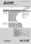
4-WAY AIR FLOW SYSTEM
8-1. FRESH AIR INTAKE (LOCATION FOR INSTALLATION)
At the time of installation, use the duct holes (cut out) located at the positions shown in following diagram, as and when required.
Fresh air intake
Detail drawing of fresh air intake
25
[100
[73.4
Cut out hole
0°
12
12
0°
118
3-[2.8 hole
Burring hole
Ceiling surface
Refrigerant pipe
Electrical Box
Drain pipe
8-2. FRESH AIR INTAKE AMOUNT & STATIC PRESSURE CHARACTERISTICS
SLZ-KA25VAL(1).TH
SLZ-KA25VA(1).TH
SLZ-KA35VA(1).TH
SLZ-KA35VAL(1).TH
SLZ-KA50VA(1).TH
SLZ-KA50VAL(1).TH
Taking air into the unit
How to read curves
2.5
Duct characteristics
at site
0
A
2.0
Air flow : Q [m
3.0 3.5
Curve in the
left graphs
1
C
3/min]
B
Static pressure : P [Pa]
50
0.5 1.0 1.5
0
Q
-50
-100
C
A
2
E
-150
-200
Q
-250
3
NOTE: Fresh air intake amount should be 20% or less of
whole air amount to prevent dew dripping.
A
D
-300
Q…Designed amount of fresh air intake
<m3/min>
A…Static pressure loss of fresh air
intake duct system with air flow
amount Q
<Pa>
…
B Forced static pressure at air conditioner inlet with air flow amount Q
<Pa>
C…Static pressure of booster fan with
air flow amount Q
<Pa>
D…Static pressure loss increase
amount of fresh air intake duct system for air flow amount Q
<Pa>
E…Static pressure of indoor unit with air
flow amount Q
<Pa>
Qa…Estimated amount of fresh air
3
intake without D
<m /min>
Q
Qa
8-3. OPERATION IN CONJUNCTION WITH DUCT FAN (BOOSTER FAN)
●Whenever the indoor unit operates, the
duct fan operates.
(1)Connect the optional multiple remote
controller adapter(PAC-SA88HA-E)
to the connector CN51 on the indoor
controller board.
(2)Drive the relay after connecting the
12V DC relay between the Yellow
and Orange connector wires.
Use a relay of 1W or smaller.
MB: Electromagnetic switch power
relay for duct fan.
X: Auxiliary relay (12V DC LY-1F)
Be sure to secure insulation
material by tape, etc.
CN51
on
indoor unit
board
5
~
Green
Yellow
1
Connector (5P)
Orange
MB
Red
Brown
Indoor unit side
Multiple remote
controller adapter
PAC-SA88HA-E
Installation at site
Be sure to secure insulation
material by tape, etc.
Indoor controller board
Multiple remote
controller adapter
PAC-SA88HA-E
Distance between indoor
controller board and relay
must be within 10m.
CN51(WHT)
CN51
25
OC320B-1.qxp
07.7.19 8:45 AM
Page 26
8-4. FIXING HORIZONTAL VANE
Horizontal vane of each air outlet can be fixed according to the environment where it is installed.
Setting procedure
1) Turn off a main power supply (Turn off a breaker).
2) Remove the vane motor connector in the direction of the arrow shown below with pressing the unlocking button as in the
figure below.
Insulate the disconnected connector with the plastic tape.
Vane motor
Vane motor
Connector
Unlocking button
Horizontal vane
3) Set the vertical vane of the air outlet by hand slowly within the range in the table below.
Measured standard
position of the grille
Horizontal vane
<Set range>
Standard of
horizontal position
Level 30°
(Min.)
Downward 45°
Downward 55°
Downward 70°
(Max.)
Dimension A (mm)
21
25
28
30
w Dimension between 21 mm and 30 mm can be arbitrarily set.
Caution
.
Do not set the dimension out of the range.
Erroneous setting could cause dew drips, smudge on ceiling or malfunction of unit.
26
OC320B-1.qxp
07.7.19 8:45 AM
9
Page 27
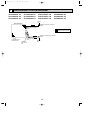
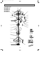
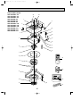
DISASSEMBLY PROCEDURE
SLZ-KA25VAL.TH
SLZ-KA35VAL.TH
SLZ-KA50VAL.TH
SLZ-KA25VA.TH
SLZ-KA35VA.TH
SLZ-KA50VA.TH
SLZ-KA25VAL1.TH
SLZ-KA35VAL1.TH
SLZ-KA50VAL1.TH
SLZ-KA25VA1.TH
SLZ-KA35VA1.TH
SLZ-KA50VA1.TH
Be careful on removing heavy parts.
OPERATING PROCEDURE
PHOTOS&ILLUSTRATIONS
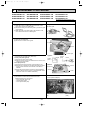
1. Removing the air intake grille
(1) Slide the knob of air intake grille to the direction of the
arrow 1 to open the air intake grille.
(2) Remove the string hook from the panel to prevent the grille
from dropping.
(3) Slide the hinge of the intake grille to the direction of the
arrow 2 and remove the air intake grille.
Figure 1
Air intake grille
Grille
Air intake grille knob
2. Removing the fan guard
(1) Open the air intake grille.
(2) Remove the 3 screws of fan guard.
Photo 1
Fan guard
Screws
Air intake grille
3. Removing the panel
(1) Remove the air intake grille. (Refer to 1)
Corner panel (See figure 2)
(1) Remove the screw of the corner.
(2) Slide the corner panel to the direction of the arrow 3, and
remove the corner panel.
Panel (See photo 2)
(1) Disconnect the connector that connects with the unit.
(2) Remove the 2 screws from the panel and loose another 2
screws, which are fixed to the oval hole, have different
diameter.
(3) Rotate the panel a little to remove the screws.(Slide the
panel so that the screw comes to a larger diameter of the
oval hole, which has 2 different diameters.)
Figure 2
Corner
Screw panel
Panel
Corner
panel
Photo 2
Screws
Connectors
Screws
Panel
Photo 3
4. Removing the electrical parts
(1) Remove the 2 screws and the control box cover.
<Electrical parts in the control box>
• Indoor controller board (I.B)
• Terminal block (TB4)
• Indoor power board (P.B)
Indoor power board(P.B)
Indoor controller board
(I.B)
27
Terminal block
(TB4)
OC320B-1.qxp
07.7.19 8:45 AM
Page 28
OPERATING PROCEDURE
PHOTOS&ILLUSTRATIONS
5. Removing the room temperature thermistor (TH1)
(1) Remove the panel. (Refer to 3)
(2) Pull out the room temperature thermistor from the drain
pan.
(3) Remove the 2 screws fixed to the control box cover, and
remove the control box cover.
(4) Remove the connector (CN20) from the indoor controller
board, and disconnect the room temperature thermistor.
Photo 4
Connectors
Drain plug
Control box
Screw
Screw
Room
temperature
thermistor
(TH1)
6. Removing the drain pan
(1) Remove the panel. (Refer to 3)
(2) Remove the room temperature thermistor and the 2 lead
wires held with fastener; wireless controller board relay
connector (9P red) and panel relay connector (10P white).
(3) Remove the 4 screws fixed to the drain pan, and remove
the drain pan.
(4) Remove the fan guard. (Refer to 2)
7. Removing the pipe temperature thermistor/liquid (TH2)
and condenser/evaporator temperature thermistor (TH5)
(1) Remove the panel. (Refer to 3)
(2) Remove the drain pan. (Refer to 6)
(3) Disconnect the indoor coil thermistor from the holder.
(4) Remove the 3 screws fixed to the piping cover, and
remove the piping cover. (See photo 9)
(5) Remove the 2 screws fixed to the control box cover, and
remove the control box cover.
Drain pan
Screw
Screw
Fan guard
Control box
Photo 5
Pipe temperature thermistor/liquid (TH2)
(6) Remove the connector (CN21) from the indoor controller
board, and disconnect the pipe temperature thermistor/liquid.
Condenser/evaporator temperature thermistor (TH5)
(6) Remove the connector (CN29) from the indoor controller
board, and disconnect the condenser/evaporator temperature
thermistor.
Pipe temperature
thermistor/liquid
(TH2)
8. Removing the fan motor (MF)
(1) Remove the panel. (Refer to 3)
(2) Remove the drain pan. (Refer to 6)
(3) Remove the nut and the washer from the turbo fan, and
remove the turbo fan.
(4) Remove the 2 screws fixed to the control box cover, and
remove the control box cover.
(5) Disconnect the connectors of the (fan 1) and the (fan 2)
from the indoor controller board.
(6) Remove the 3 screws fixed to the piping cover, and
remove the piping cover. (See photo 9)
(7) Remove the 6 screws fixed to the flat plate, and remove
the flat plate.
(8) Disconnect the lead wires to the direction of the fan motor,
and remove the 3 nuts of the fan motor.
28
Photo 6
Condenser/evaporator
temperature thermistor
(TH5)
Flat plate
Screws
Screw
Nut
Fan motor
(MF)
Nut
Lead
wires
Screws
Screw
Nut
OC320B-1.qxp
07.7.19 8:45 AM
Page 29
OPERATING PROCEDURE
PHOTOS&ILLUSTRATIONS
9. Removing the drain pump (DP) and drain sensor (DS)
(1) Remove the panel. (Refer to 3 )
(2) Remove the drain pan. (Refer to 6)
(3) Remove the 2 screws fixed to the control box cover, and
remove the control box cover.
(4) Remove the connectors of the (CNP) and the (CN31)
from the indoor controller board.
(5) Remove the 1 screw fixed to the cover, and remove the
cover.
(6) Disconnect the lead wires to the direction of the drain
pump.(See photo 7)
(7) Remove the 3 screws of the drain pump.
(8) Cut the drain hose band, pull out the drain hose from the
drain pump.
(9) Pull out the drain pump.
(10) Remove the drain sensor and the holder.
Photo 7
Cover
Screw
Control
box
Lead wires
Photo 8
Drain sensor (DS)
Drain pump (DP)
Drain
hose
Screws
Screw
Fixing band
10. Removing the heat exchanger
(1) Remove the panel. (Refer to 3 )
(2) Remove the drain pan. (Refer to 6)
(3) Remove the nut and the washer from the turbo fan, and
remove the turbo fan.
(4) Remove the 2 screws fixed to the control box cover, and
remove the control box cover.
(5) Disconnect the connector of the (fan) from the indoor controller board.
(6) Remove the 3 screws fixed to the piping cover, and
remove the piping cover. (See photo 9)
(7) Remove the pipe temperature thermistor/liquid and
condenser/evaporator temperature thermistor. (Refer to 7)
(8) Disconnect the lead wires to the direction of the fan motor.
(9) Remove the 1 coil support screw, the 2 inside coil screws
(See photo 10), and the 4 outside coil screws (See photo 9)
from the heat exchanger, and remove the heat exchanger.
Control box
Photo 9
Screws of
piping cover
Coil
screws
Coil
screws
Piping cover
Lead wires
Control box
Photo 10
Coil screws
Coil
support
Coil
support
Screw
Heat exchanger
29
OC320B-1.qxp
07.7.19 8:45 AM
10
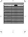
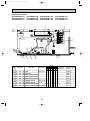
Page 30
PARTS LIST (Non RoHS compliant)
PANEL PARTS
SLP-2AL(FOR SLZ-KA25/35/50VAL.TH)
SLP-2AA(FOR SLZ-KA25/35/50VA.TH)
10
9
8
3
2
7
1
4
5
6
Q'ty/set
No.
Parts No.
Parts name
Specification
SLP-2AL SLP-2AA
Wiring RecomDiagram mended
Symbol
Q'ty
1
E07
103
003 AIR OUTLET GRILLE
E07
158
003 AIR OUTLET GRILLE
2 E07
103
317 WIRELSS REMOTE CONTROL BOARD
1
3 E07
103
037 AUTO VANE
4
4
4 E07
103
975 CORNER PANEL
4
4
5 E07
103
100 AIR FILTER
1
1
6 E07
103
010 INTAKE GRILLE
1
1
7 E07
103
303 VANE MOTOR
4
4
8
1
Remarks
(Drawing No.)
1
W.B
8 E07
103
044 VANE BUSH
8
9 E07
103
031 GEAR (V)
4
4
10 E07
103
032 GEAR (M)
4
4
30
MV
OC320B-2.qxp
07.7.19 8:43 AM
Page 31
ELECTRICAL PARTS
SLZ-KA25VAL.TH SLZ-KA25VA.TH
SLZ-KA35VAL.TH SLZ-KA35VA.TH
SLZ-KA50VAL.TH SLZ-KA50VA.TH
6
5
1
No.
Parts No.
2
4
UNIT
TO OUTDOOR
7
3
Parts name
Q'ty/set
SLZ-KA
Specification
25 35 50 25 35 50
VAL.TH VA.TH
1 1 1 1 1 1
250V 6.3A
1 E07
006
382 FUSE
2 E02
661
385 VARISTOR
1 1
1
E07
162
447 INDOOR CONTROLLER BOARD
3 E07
164
447 INDOOR CONTROLLER BOARD
1
1 1
1
166
447 INDOOR CONTROLLER BOARD
162
375 TERMINAL BLOCK
3P(S1,S2,S3)
5 E07
156
375 TERMINAL BLOCK
2P(1,2)
6 E07
154
440 INDOOR POWER BOARD
1 1
7 E02
095
350 INDOOR FAN CAPACITOR 1.5+/ 440VAC
1 1
1 1
FUSE
ZNR
I.B
1
I.B
1 1
1
TB4
1 1
1
TB15
1
1 1
1
P.B
1
1 1
1
C1
1
E07
4 E07
Wiring
RecomDiagram mended
Symbol
Q'ty
I.B
1
1
31
1
Remarks
(Drawing No.)
1
OC320B-2.qxp
07.7.19 8:43 AM
Page 32
FUNCTIONAL PARTS
SLZ-KA25VAL.TH
SLZ-KA35VAL.TH
SLZ-KA50VAL.TH
SLZ-KA25VA.TH
1
SLZ-KA35VA.TH
SLZ-KA50VA.TH
23
22
3
2
22
3
21
4
20
5
19
18
17
6
16
15
7
8
ON/OFF
TOO
WARM
TOO
COOL
FAN
SELECT
VANE
TIME
AUTO COOL
HEAT DRY
24
MODE
9
RESET
10
25
11
TEMP.
12
ON/OFF
26
13
14
27
32
OC320B-2.qxp
07.7.19 8:43 AM
No.
Page 33
Parts name
Parts No.
Q'ty/set
SLZ-KA
Specification
25 35 50 25 35 50
VAL.TH VA.TH
1 E07
104
290 BASE
1 1
1
1 1
1
2 E07
104
124 DRUM-1
1 1
1
1 1
1
3 E07
104
808 LEG-1
2 2
2
2 2
2
4 E07
105
124 DRUM-2
1 1
1
1 1
1
E07
140
620 INDOOR HEAT EXCHANGER
1
5 E07
141
620 INDOOR HEAT EXCHANGER
E07
142
620 INDOOR HEAT EXCHANGER
6 E07
104
105 MOTOR MOUNT
E07
162
300 INDOOR FAN MOTOR
PK6V15-LD
7 E07
164
300 INDOOR FAN MOTOR
PK6V20-LL
PK6V20-LM
Remarks
(Drawing No.)
Wiring RecomDiagram mended
Symbol
Q'ty
1
1
1
1
1
3 3
3
3 3
3
1
1
MF
1
1
3PCS/SET
MF
1
1
E07
166
300 INDOOR FAN MOTOR
8 E07
104
816 FLAT PLATE
1 1
1
1 1
1
9 E07
104
502 TURBO FAN
1 1
1
1 1
1
10 E07
104
097 SPL WASHER
1 1
1
1 1
1
11 E07
104
700 DRAIN PAN
1 1
1
1 1
1
12 E07
154
308 ROOM TEMPERATURE THERMISTOR
1 1
1
1 1
1
13 E07
104
520 FAN GUARD
1 1
1
1 1
1
14 E07
104
524 DRAIN PLUG
1 1
1
1 1
1
15 E07
104
648 COIL SUPPORT
1 1
1
1 1
1
1 1
1
1 1
1
TH5
TH2
CONDENSER / EVAPORATOR
TEMPERATURE THERMISTOR
16 E07
154
309
17 E07
154
307 PIPE TEMPERATURE THERMISTOR / LIQUID
1 1
1
1 1
1
18 E07
104
702 DRAIN HOSE
1 1
1
1 1
1
19 E07
104
266 DRAIN SENSOR
1 1
1
1 1
1
20 E07
104
241 SENSOR HOLDER
1 1
1
1 1
1
21 E07
104
355 DRAIN PUMP
1 1
1
1 1
1
22 E07
104
809 LEG-2
2 2
2
2 2
2
23 E07
154
006 COVER (DRUM)
1 1
1
1 1
1
24 E07
140
426 WIRELESS REMOTE CONTROLLER
1 1
1
25 E02
527
083 REMOTE CONTROLLER HOLDER
1 1
1
26 E07
159
426 REMOTE CONTROLLER
1 1
1
27 E07
018
089 REMOTE CONTROLLER CABLE
1 1
1
33
MF
TH1
DS
DP
W.R
OC320B-2.qxp
07.7.19 8:43 AM
11
Page 34
RoHS PARTS LIST
PANEL PARTS
SLP-2AL (FOR SLZ-KA25/35/50VAL.TH)
SLP-2AA (FOR SLZ-KA25/35/50VA.TH)
SLP-2ALW (FOR SLZ-KA25/35/50VAL1.TH)
SLP-2AAW (FOR SLZ-KA25/35/50VA1.TH)
10
9
8
3
2
7
1
4
5
No.
RoHS
6
Q'ty/set
Parts No.
Parts name
Specification
AL
103
003 AIR OUTLET GRILLE
G E17
158
003 AIR OUTLET GRILLE
G E17
423
003 AIR OUTLET GRILLE
G E17
424
003 AIR OUTLET GRILLE
2 G E17
103
317 WIRELSS REMOTE CONTROL BOARD
1
G E17
103
037 AUTO VANE
4
G E17
423
037 AUTO VANE
G E17
103
975 CORNER PANEL
G E17
423
975 CORNER PANEL
3
4
AA ALW AAW
1
1
1
W.B
1
4
4
4
1
1
4
4
4
4
1
1
1
1
5 G E17
103
100 AIR FILTER
1
G E17
103
010 INTAKE GRILLE
1
G E17
423
010 INTAKE GRILLE
7 G E17
103
303 VANE MOTOR
4
4
4
4
8 G E17
103
044 VANE BUSH
8
8
8
8
9 G E17
103
031 GEAR (V)
4
4
4
4
10 G E17
103
032 GEAR (M)
4
4
4
4
6
Wiring RecomDiagram mended
Symbol
Q'ty
1
G E17
1
Remarks
(Drawing No.)
SLP-2
34
MV
07.7.19 8:43 AM
Page 35
ELECTRICAL PARTS
SLZ-KA25VAL.TH
SLZ-KA25VA.TH
SLZ-KA35VAL.TH
SLZ-KA35VA.TH
SLZ-KA50VAL.TH
SLZ-KA50VA.TH
SLZ-KA25VAL1.TH
SLZ-KA35VAL1.TH
SLZ-KA50VAL1.TH
SLZ-KA25VA1.TH
SLZ-KA35VA1.TH
SLZ-KA50VA1.TH
6
5
TO OUTDOOR
7
No.
RoHS
1
Parts No.
2
4
UNIT
OC320B-2.qxp
3
Parts name
Q'ty/set
SLZ-KA
Specification
25 35 50 25 35 50
VAL(1).TH VA(1).TH
1 1 1 1 1 1
250V 6.3A
1 G E17
006
382 FUSE
2 G E12
661
385 VARISTOR
1 1
G E17
162
447 INDOOR CONTROLLER BOARD
1
3 G E17
164
447 INDOOR CONTROLLER BOARD
G E17
166
447 INDOOR CONTROLLER BOARD
4 G E17
162
375 TERMINAL BLOCK
3P(S1,S2,S3)
5 G E17
156
375 TERMINAL BLOCK
2P(1,2)
6 G E17
154
440 INDOOR POWER BOARD
1 1
7 G E12
095
350 INDOOR FAN CAPACITOR 1.5+/ 440VAC 1 1
1
1 1
1
FUSE
ZNR
I.B
1
I.B
1 1
1
TB4
1 1
1
TB15
1
1 1
1
P.B
1
1 1
1
C1
1
1 1
Wiring RecomDiagram mended
Symbol
Q'ty
I.B
1
1
35
1
Remarks
(Drawing No.)
1
OC320B-2.qxp
07.7.19 8:43 AM
Page 36
FUNCTIONAL PARTS
SLZ-KA25VAL.TH
SLZ-KA35VAL.TH
SLZ-KA50VAL.TH
SLZ-KA25VA.TH
1
SLZ-KA35VA.TH
SLZ-KA50VA.TH
SLZ-KA25VAL1.TH
2
SLZ-KA35VAL1.TH
SLZ-KA50VAL1.TH
SLZ-KA25VA1.TH 3
SLZ-KA35VA1.TH
SLZ-KA50VA1.TH
23
22
3
22
21
4
20
5
19
18
17
6
16
15
7
8
ON/OFF
TOO
WARM
TOO
COOL
FAN
SELECT
VANE
TIME
AUTO COOL
HEAT DRY
24
MODE
9
RESET
10
25
11
TEMP.
12
ON/OFF
26
13
14
27
36
No.
07.7.19 8:43 AM
RoHS
OC320B-2.qxp
Page 37
Parts name
Parts No.
Q'ty/set
SLZ-KA
Specification
25 35 50 25 35 50
VAL(1).TH VA(1).TH
1 1 1 1 1 1
Remarks
(Drawing No.)
Wiring RecomDiagram mended
Symbol
Q'ty
1 G E17
104
290 BASE
2 G E17
104
124 DRUM-1
1 1
1
1 1
1
3 G E17
104
808 LEG-1
2 2
2
2 2
2
4 G E17
105
124 DRUM-2
1 1
1
1 1
1
G E17
140
620 INDOOR HEAT EXCHANGER
1
5 G E17
141
620 INDOOR HEAT EXCHANGER
G E17
142
620 INDOOR HEAT EXCHANGER
6 G E17
104
105 MOTOR MOUNT
G E17
162
300 INDOOR FAN MOTOR
PK6V15-LD
7 G E17
164
300 INDOOR FAN MOTOR
PK6V20-LL
G E17
166
300 INDOOR FAN MOTOR
PK6V20-LM
8 G E17
104
816 FLAT PLATE
1 1
1
1 1
1
9 G E17
104
502 TURBO FAN
1 1
1
1 1
1
10 G E17
104
097 SPL WASHER
1 1
1
1 1
1
11 G E17
104
700 DRAIN PAN
1 1
1
1 1
1
12 G E17
154
308 ROOM TEMPERATURE THERMISTOR
1 1
1
1 1
1
13 G E17
104
520 FAN GUARD
1 1
1
1 1
1
14 G E17
104
524 DRAIN PLUG
1 1
1
1 1
1
15 G E17
104
648 COIL SUPPORT
1 1
1
1 1
1
1 1
1
1 1
1
TH5
TH2
1
1
1
1
1
3 3
CONDENSER / EVAPORATOR
TEMPERATURE THERMISTOR
3
3 3
3
1
1
MF
1
1
MF
1
1
16 G E17
154
309
17 G E17
154
307 PIPE TEMPERATURE THERMISTOR / LIQUID
1 1
1
1 1
1
18 G E17
104
702 DRAIN HOSE
1 1
1
1 1
1
19 G E17
104
266 DRAIN SENSOR
1 1
1
1 1
1
20 G E17
104
241 SENSOR HOLDER
1 1
1
1 1
1
21 G E17
104
355 DRAIN PUMP
1 1
1
1 1
1
22 G E17
104
809 LEG-2
2 2
2
2 2
2
23 G E17
154
006 COVER (DRUM)
1 1
1
1 1
1
24 G E17
140
426 WIRELESS REMOTE CONTROLLER
1 1
1
25 G E12
527
083 REMOTE CONTROLLER HOLDER
1 1
1
26 G E17
159
426 REMOTE CONTROLLER
1 1
1
27 G E17
018
089 REMOTE CONTROLLER CABLE
1 1
1
37
3PCS/SET
MF
TH1
DS
DP
W.R
OC320B-2.qxp
07.7.19 8:43 AM
Page 38
38
OC320B-2.qxp
07.7.19 8:43 AM
Page 39
39
OC320B-2.qxp
07.7.19 8:43 AM
Page 40
HEAD OFFICE : TOKYO BLDG., 2-7-3, MARUNOUCHI, CHIYODA-KU, TOKYO 100-8310, JAPAN
CCopyright 2005 MITSUBISHI ELECTRIC ENGINEERING CO., LTD.
Distributed in Jul. 2007 No.OC320 REVISED EDITION-B PDF 7
Distributed in Sep. 2006 No.OC320 REVISED EDITION-A PDF 7
Distributed in Feb. 2005 No.OC320 PDF 8
Made in Japan
New publication, effective Jul. 2007
Specifications subject to change without notice.