1
Service Manual
OASIS
Oxygen And Suction Integrated System
Oasis
© Copyright
No part of this manual may be copied for any reason without the written permission of BPR Medical Ltd.
Manufactured By:
BPR Medical Ltd
22 Hamilton Way, Mansfield, NG18 5BU
United Kingdom
Tel: +44 (0)1623 628281
Fax: +44 (0)1623 628289
Table of Contents
TABLE OF CONTENTS .................................................................................... 2
1.0
DESCRIPTION OF SYMBOLS ................................................................... 3
2.0
PRODUCT DESCRIPTION ....................................................................... 3
3.0
APPROVALS ......................................................................................... 3
4.0
GENERAL SAFETY WARNINGS ................................................................ 4
5.0
INSPECTION AND MAINTENANCE PERIODS.............................................. 5
6.0
SPECIFICATION ................................................................................... 6
7.0
SUCTION JAR SYSTEMS ........................................................................ 7
8.0
DECONTAMINATION CERTIFICATE .......................................................... 8
9.0
PROCEDURES FOR PERIODIC INSPECTION .............................................. 8
10.0 PROCEDURES FOR FUNCTIONAL CHECK .................................................. 9
10.1
Flow Rate Test
9
10.2
Suction Flow Test
9
10.3
Vacuum Pressure
9
10.4
Suction Leak-Through
9
10.5
Flowmeter Leak-Through
9
10.6
Oasis Leak Test
9
11.0 PROCEDURES FOR SERVICING ............................................................. 10
11.1
Flowmeter Module
10
11.2
Flowmeter Sub Assembly
11
11.3
Suction Control Assembly
12
11.4
Suction Venturi
13
11.5
Suction Barb and Gauge
14
11.6
Swivel Elbow Assembly
15
12.0 ADDITONAL PROCEDURES FOR REPAIR ................................................. 16
12.1
Suction Gauge Assembly
16
12.2
Low Gas Pressure Indicator
17
12.3
Swivel Elbow Assembly
18
13.0 SPARE PARTS .................................................................................... 19
13.1
Service Parts & Kits
19
14.0 NOTES .............................................................................................. 19
Oasis Service Manual
702-0037.7
June 2010
Page 2 of 19
Oasis
1.0
Description of Symbols
Attention, see Instructions for Use
Use no oil
2.0
Product Description
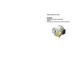
Oasis is an oxygen flowmeter and a suction regulator integrated into one device, driven by a single oxygen
cylinder.
It is designed to provide controllable delivery of supplemental oxygen and suction in emergency situations or
when patients are being moved on patient trolleys.
Oasis is intended to be fitted to the head end of patient trolleys to provide easy access to both oxygen and
suction where and when it is needed most. The integrated, sturdy design provides protection from damage
in a harsh environment.
The oxygen flowmeter is of fixed orifice type, providing eleven pre-set flow rates selectable by turning the
control knob to the required position. The flow rate at each position is shown through a window in the body
of the flowmeter and is given in units of litres per minute (lpm). The patient or outlet connection barb is
situated underneath the Oasis directly below the flowmeter control knob.
The suction device comprises a variable vacuum source to which a proprietary suction jar system can be
connected. Vacuum is generated using the venturi principle. On turning the control knob, oxygen is fed to
the venturi generator, which in turn provides a vacuum at the suction barb. The amount of vacuum is
indicated by the vacuum gauge indicated in units of minus Kilo Pascals (-kPa) and minus Bar (-Bar).
Vacuum is only noticeable on the gauge when an obstruction is perceived by the system. Occluding the
output port or hose with your finger is a simple way of testing system performance.
To provide early indication that a cylinder is empty or has been turned off, a low pressure indicator is
included. The indicator, situated on the front panel, shows red when there is no gas present. A pressure
regulator is provided with the Oasis to reduce the high cylinder pressure to a safe working level. The
regulator is permanently connected to the Oasis manifold.
3.0
Approvals
Oasis is a CE Marked device in accordance with the Medical Device Directive (93/42/EEC) and meets the
requirements of the following Harmonised Standards:
EN738-1............ Pressure Regulators and Pressure Regulators with Flowmetering Devices
EN10079-3 ........ Suction Equipment Powered from Vacuum or Pressure Source
Oasis Service Manual
702-0037.7
June 2010
Page 3 of 19
Oasis
4.0
W1
W2
General Safety Warnings
Before using or servicing this equipment read
through
the
entire
instruction
manual.
Attempting to use this equipment without an
appreciation of its correct operation, its
limitations and the general safety warnings
associated with compressed oxygen may result
in patient or user injury.
Oxygen therapy may be a critical treatment. A
flowmeter should be used in strict accordance
with the prescription and instructions of a
qualified
clinician.
The
effectiveness
of
supplemental oxygen therapy can only be
determined by continuous monitoring of blood
oxygen levels. It is essential that PaO2 or SpO2
monitoring is carried out when supplemental
oxygen is prescribed.
W3
Ensure that the oxygen cylinder is securely
fastened to the trolley base.
W4
When the flowmeter is turned off isolate the
patient from the equipment by disconnecting
the delivery tube from either the patient or the
flowmeter.
W5
Only appropriately skilled service personnel
working in controlled conditions must perform
disassembly, assembly and testing of this
equipment.
W6
Do not submerge in water or allow any fluid to
enter the equipment. If you have reason to
suspect that fluid or other ingress has occurred
remove the device from use and contact the
manufacturer.
W7
The performance of the device may be affected
if it is stored or transported in temperatures
outside of the range -20oC to +60oC.
W8
Check the cylinder contents before use and at
regular intervals during use, as low cylinder
pressure may result in poor or non-performance
of the equipment. Always change the oxygen
cylinder when the oxygen cylinder contents
gauge is showing red.
W9
Hydrophobic filters for re-useable suction jars
and disposable liner systems are designed for
single use only and must be replaced after
every patient use. Single Use products should
be disposed of in accordance with hospital
protocols. Do not attempt to clean and re-use
disposable filters or liners.
W10 Oasis has been tested with the suction jar
systems indicated in this manual. The use of
suction jar systems other than those listed
and/or approved by the manufacturer may
result in poor or non-performance of the
equipment.
W11 The accuracy of the flowmeter and suction
device may be affected if the input pressure is
other than that stated in the specifications.
oil or grease become highly combustible in the
presence of oxygen. Oxygen must never be
allowed to contact oil, grease or other
petroleum-based substances.
W13 Never administer oxygen while smoking or when
near an open flame.
W14 Oxygen cylinders have fill
000 kPA (200 Bar). Never
from a cylinder without
pressure to a safe level
pressure regulator.
W15 Ensure that the threaded fittings or indexing
pins on the regulator are properly mated and
tightened before opening the cylinder valve.
W16 Never install a pin index regulator with more
than one Yoke Seal between the cylinder and
the regulator. Before attaching the regulator
verify that the post valve is not already fitted
with a Yoke Seal. Never add a second Yoke
Seal to the regulator inlet while one is in place.
W17 Make sure that the pin-indexed or threaded
fittings on the regulator inlet are compatible
with the gas cylinder on which it is to be fitted.
Never attempt to force an incompatible
connection.
W18 The threaded bullnose connection on a UK
medical oxygen cylinder may be the same as
that for a UK medical air cylinder, ensure that
you have the correct cylinder for the application.
Oasis and its regulator are intended for use with
oxygen only and must not be connected to an
air cylinder.
W19 Before removing a regulator from a cylinder
fully close the cylinder valve and release all gas
from the regulator.
W20 Never use oxygen as a pressure medium to
purge obstructed pipelines or equipment, to
operate pneumatic tools, or to build up any
pressure in tanks.
W21 Never permit compressed medical gases to
enter a regulator suddenly. Always open the
cylinder valve slowly. Do not stand in front of a
regulator outlet when opening the cylinder
valve.
W22 Do not use or store oxygen equipment near
excessive heat (>50oC or 125oF) or an open
flame.
W23 Use only lubricants recommended by the
manufacturer when servicing the Oasis.
The
use of lubricants other than those recommended
by the manufacturer may result in fire or
explosion.
W24 Oasis must always be used in an upright
position. When fitting Oasis to a patient trolley
ensure that the front membrane panel is
vertical.
W12 Oxygen is not flammable, but the presence of
oxygen will drastically increase the rate and
severity of combustion. Hydrocarbons such as
Oasis Service Manual
702-0037.7
June 2010
pressures up to 20
use medical oxygen
first reducing the
through a suitable
Page 4 of 19
Oasis
5.0
Inspection and Maintenance Periods
Periodic Inspection (6 Monthly)
Can be performed with Oasis still connected to the patient trolley and in the hospital department in which
the trolley is located.
Function Check (Annual)
Performance check on Oasis. Requires appropriate test equipment and therefore may require disassembly
from the patient trolley for work to be done in workshop conditions.
Full Service (4 Years)
Strip down Service and full functional check. Requires appropriate test equipment and will require
disassembly from the patient trolley for work to be done in workshop conditions.
Oasis Service Manual
702-0037.7
June 2010
Page 5 of 19
Oasis
6.0
Specification
General
Operating, Storage and
Transport
Temperature Range
Warranty
Flowmeter
Nominal Flow Rate
Flow Accuracy
-20oC to 60oC
1 Year
0, 0.5, 1, 1.5, 2, 3, 4, 5, 6, 8,10, 15
±10% of setting at 1 lpm and above, ±20% of setting below 1 lpm across the
full input range
Effect on accuracy as a
result of:
i) varying inlet pressure
ii ) varying outlet
resistance
iii ) varying temperature
Typically less than 15% change across the input pressure range
Less than 1% of reading up to 5kPa (50cmH2O) back pressure
Delivery Hose
6.0 mm inside diameter
Less than 0.2% of reading per degree Celsius
Medium Suction
Option (60 kPa)
Suction
Vacuum Range
Vacuum Flow
Gas consumption
(typical)
Recommended Suction
Hose
ISO EN 10079-3 Rating
30 lpm
0 to –50 kPa (+5kPa/30kPa)
38 – 60 lpm
85 lpm max
7.5mm inside diameter
7.5mm inside diameter
7.5mm inside diameter
Medium Vacuum
Equipment
Medium Vacuum
equipment
Medium Vacuum
Equipment
Input
900 kPa
Pressure [kPa]
Outlet
Pressure
0 to –55 kPa (+5kPa/30kPa
15-25 lpm
20 000 kPa
Pressure [kPa]
Minimum
[kPa]
Stated at 10 000 kPa
400 kPa
Input Pressure and flow
of 1 lpm
Maximum Flow Capacity
100 lpm
[lpm]
(Q1) Standard Discharge
30
[lpm]
(P2) Outlet Pressure
[kPa]
400
Stated at Input Pressure P3 and
flow Q1
Oasis Service Manual
702-0037.7
June 2010
High Suction Option
(150kPa)
0 to –60 kPa (+5kPa/30kPa)
10 – 16 lpm
20 lpm
Regulator
(P1) Maximum Input
(P3)
Medium/High Suction
Option( 90 kP)a
Page 6 of 19
Oasis
7.0
Suction Jar Systems
Oasis has been tested and found to be compatible with the suction jar systems detailed in the table below.
Some 2 Litre size jars shown in the table, whilst compatible with the Oasis suction regulator, are too tall and
are liable to be broken should the trolley be lowered or put into the Trendelenberg position. These suction
jar systems are therefore not compatible with Oasis and are shown with the manufacturer’s part number
crossed out (e.g. XXX XXXX). For the same reason all 3 Litre and larger suction jar systems are
incompatible with Oasis.
Suction Jar Size
0.8/1.0 Litre
1.2/1.5 Litre
2.0 Litre
W064
L212
A
E124
F807
A
E123
F806
1212CE
1220CE
Abbott
Receptal
Re-useable suction jar for disposable liner
Disposable liner
Oasis cradle type
Allegiance
Medi-Vac
Guardian
Disposable canister
B
Oasis cradle type
Medi-Vac
Flex
Advantage
Medi-Vac
CRD
Re-useable suction jar for disposable liner
65652-611
65652-616
Disposable liner
Oasis cradle type
65651-910
B
65651-920
B
Re-useable suction jar for disposable liner
65652-511
65652-516
1510CE
B
1515CE
B
8888-310003
B
8888-310052
B
8888-310151
8888-310839
8888-310821
B
8888-310813
8888-310805
Disposable liner
Oasis cradle type
Tyco
Sep-T-Vac
Disposable canister
Oasis cradle type
Re-useable suction jar for disposable liner
Disposable liner
Oasis cradle type
VacSax
Oasis cradle type
3833-132
9910-340
B
Autoclavable suction jar
MAK1000
Re-useable suction jar for disposable liner
Disposable liner
Flowmeter
Spa
Monokit
Autoclavable
A
Oasis cradle type
Monokit
Disposable
Re-useable suction jar for disposable liner
Disposable liner
5113080
Oasis cradle type
Oasis Service Manual
702-0037.7
June 2010
Page 7 of 19
B
3833-090
9910-208
B
Oasis
8.0
Decontamination Certificate
A valid decontamination certificate must accompany equipment returned for servicing. For reasons of Health
& Safety, equipment returned to BPR Medical for service without a valid decontamination certificate cannot
be accepted and will be returned without further processing.
9.0
Procedures for Periodic Inspection
The following safety warnings apply. Please read them carefully before you proceed: W1, W3, W5, W6, W7,
W8, W9, W10, W11, W12, W13, W15, W16, W17, W18, W19, W20, W21, W22, W23 and W24
Undertake Periodic Inspection every 6 months or when there is reason to believe that the device has
sustained damage or may not be working correctly. The aim of this inspection is to identify partial or
complete function loss only.
Suction/Vacuum Gauge
Check gauge is in good condition, is appropriately aligned and does not appear damaged. Check function by
turning the vacuum on (suction controller knob anti-clockwise with cylinder charged and turned on), place a
finger over the suction barb outlet and check the gauge dial moves smoothly to a level below –60kPa.
Flowmeter
Check that the flowmeter is operational. Starting at zero turn the flowmeter control knob anti-clockwise
through each position and ensure that oxygen is flowing at each setting.
Low Pressure Indicator
With a charged cylinder connected and turned on, check that the Low Pressure Indicator is withdrawn. Turn
the cylinder off and discharge any oxygen in the system by turning on the suction control/flowmeter. The
Indicator should move forward smoothly and show red.
High Pressure Hose
Inspect the high pressure oxygen hose assembly for damage or wear. Ensure that the swivel connection at
the back of the Oasis moves freely.
Oasis Fixing
Oasis should be fixed horozontally to the patient trolley in a secure manner. Check that the Oasis is secure
and that there is no movement. Tighten or reposition by adjustment of the two grub screws accessed from
the back of the Oasis bracket. Check also the Suction Jar cage is secured adequately to the base of the
trolley.
General Condition
Inspect the Oasis for signs of general damage or disrepair.
Service Due?
A Service Due date is detailed on the rating label, which should be checked to determine when service is
next due.
Oasis Service Manual
702-0037.7
June 2010
Page 8 of 19
Oasis
10.0 Procedures for Functional Check
The following safety warnings apply. Please read them carefully before you proceed: W1, W3, W5, W6, W7,
W8, W9, W10, W11, W12, W13, W15, W16, W17, W18, W19, W20, W21, W22, W23 and W24
A calibrated flowmeter with a maximum flow of at least 15 lpm and an accuracy of better than +/- 5% of
reading is required for this test.
10.1
Flow Rate Test
Connect the regulator to a 1000 KPA oxygen pressure source.
Check the flow rate at each flow setting is within tolerance. The tolerance for flow settings of between 1 lpm
to 15 lpm inclusive are +/- 10%, and +/- 20% for the 0.5 lpm flow setting.
Where a variable Oxygen pressure source is not available, the Oasis regulator can be connected to a half or
fully charged cylinder. Note, however, input pressure has a marginal effect on flow rate and this may
influence.
If the flow rates are out of tolerance in one direction (i.e. all are low or all are high) then a certain amount of
calibration can be performed by increasing/decreasing respectively the output pressure of the regulator.
Details of how to do this can be found in the Regulator Technical Manual.
10.2
Suction Flow Test
Ensure that the Oasis is connected to a charged gas supply as in 10.1 above.
Connect a 1 litre suction jar system to the Oasis Suction Barb using a 1m length of suction hosing. Take a
similar length of suction tubing from the patient side of the suction jar and immerse it in a jar containing ½
litre of tap water.
Turn the suction control knob fully on and time how long it takes to evacuate the ½ litre of water.
suction performance of the Oasis should deposit the water into the suction jar within 30 seconds.
10.3
The
Vacuum Pressure
Ensure that the Oasis is connected to a charged gas supply as in 10.1 above. Check function by turning the
vacuum on (suction controller knob anti-clockwise with cylinder charged and turned on), place your finger
over the suction barb and check the gauge dial moves smoothly below the value given in the specification
for the model of Oasis you are testing.
10.4
Suction Leak-Through
Ensure that the Oasis is connected to a charged gas supply as in 10.1 above and ensure that the Suction
and Flowmeter functions are turned off.
Unscrew the Venturi Silencer and screw the Suction Exhaust Test Barb (refer Spares Parts Lists) into the
Venturi Retainer. Connect one end of a length of hose to the Test Barb and rest the other in a glass of
water. Place a finger over the Suction Barb and check that there are no gas bubbles coming from the length
of hose, if there are then this would suggest suction leak-through.
10.5
Flowmeter Leak-Through
Ensure that the Oasis is connected to a charged gas supply as in 10.1 above and ensure that the Suction
and Flowmeter functions are turned off.
Connect one end of a length of hose to the Flowmeter Output Barb and rest the other in a glass of water.
Ensure that there are no gas bubbles coming from the length of hose, if there are then this would suggest
flowmeter leak-through.
10.6
Oasis Leak Test
Ensure that the Oasis is connected to a charged gas supply as in 10.1 above and ensure that the Suction
and Flowmeter functions are turned off. Check that the indicator is not showing.
Turn the cylinder off leaving the system charged for 30 minutes.
forward, which would suggest a leak in the system somewhere.
Oasis Service Manual
702-0037.7
June 2010
Page 9 of 19
Check that indicator does not come
Oasis
11.0 Procedures for Servicing
11.1
Flowmeter Module
The following General Safety Warnings apply:
W1, W5, W6, W12, W13, W20 & W23
38
36
a)
Disconnect Oasis from the gas supply.
b)
Remove the 4 screws securing the Mounting
Bracket.
c)
Using an 8 mm AF Open-Ended Spanner remove
the Flowmeter Output Barb.
d)
Remove the grub screws securing the dowels.
Press the flowmeter into the manifold to allow
the dowels to drop out of the manifold.
e)
Remove the Flowmeter Module.
f)
Assembly is the reverse of disassembly.
35
37
Note: When reassembling the Flowmeter fit new
Flowmeter Body and Output Probe seals.
15
40
19
5
Ident
5
15
19
35
37
38
39
40
Oasis Service Manual
702-0037.7
June 2010
Page 10 of 19
Pt. No.
602
212
212
201
208
201
602
610
0124
0030
0014
0034
0015
0035
0126
0052
Description
Flowmeter Output Barb
O-ring, 34 x 2, Nitrile
O-ring, 8 x 1.5, Viton
Screw, M4 x 6, Grub
Dowel, 3 x 30
Screw, M4 x 12, CSK
Universal Bracket
Replacement Flowmeter
Module Assembly
Qty
1
1
1
2
2
4
1
1
Oasis
11.2
Flowmeter Sub Assembly
The following General Safety Warnings apply:
W1, W5, W6, W12, W13, W20 & W23
a)
8
4
15
10
Remove the M4 Button Head Screw and
withdraw the Carrier Plate Assembly from the
flowmeter shaft.
Note: Do not
disassemble the Carrier Plate
Assembly unless there is reason to believe that
the filter has become contaminated or one of the
flow orifices has been compromised.
b)
Pull the Control Knob complete with the
Flowmeter Shaft away from the Flowmeter Body.
c)
Remove the detent springs but leave the Control
Knob Slider in place.
d)
Remove and disgard the Output O-ring Seal from
the Flow Plate Slider.
Leave the Flow Plate
Slider in place.
e)
Remove the O-ring seals from the Flow Plate
Drive Shaft and disgard; clean the shaft and the
detents machined into the bottom of the Control
Knob taking care not to allow cleaning fluid on
the Decal Label. Refit new seals on the shaft
and smear with a fine film of Krytox NRT-8908
grease before re-assembly.
f)
Clean the detent holes in the Flowmeter Output
Body, the detent balls and the detent springs.
g)
Clean the Flow Plate Slider and the bottom of the
Flowmeter Output Body. Fit new Output and
Flowmeter Body seals.
h)
Align the Control Knob Slider such that the hole
on its periphery aligns exactly with the detent
hole in the Flowmeter Body.
i)
Hold the Flowmeter Body upright to fit the
Detent Springs. Place the Detent Balls on top of
the springs and refit the Drive Shaft maintaining
compression when assembled.
j)
Maintaining compression, turn the Control Knob
so that the flowmeter reads 0 (zero).
k)
Refit the Flowplate Carrier Assembly orienting it
such that ‘no-hole no-flow’ area on the bottom of
the carrier plate is adjacent to the Output Seal.
Secure with the M4 Button Head Screw, washer
and new compression seal.
l)
Smear a fine layer of Krytox NRT-8908 grease
on the outside of the Flowmeter Body Seal to aid
re-assembly into the Oasis manifold
*Revision contingent control knob and drive
shaft may be one unit.
Oasis Service Manual
702-0037.7
June 2010
16
11
19
5
1
14
Ident
1
2
3
4
5
6
7
8
9
10
11
12
13
14
15
16
17
18
19
Page 11 of 19
2
12
3
7
9
6
18
17
13
Pt. No.
201
207
212
602
602
602
604
208
212
602
602
602
703
201
212
212
213
214
212
0028
0007
0017
0110
0124
0095
0028
0009
0015
0117
0109
0093
0107
0025
0030
0041
0007
0001
0014
Description
Screw, M4 x 8, Button Head
Washer, 4mm
O-ring, 6 x 1.5, Nitrile
Flow Plate Slider
Flowmeter Output Barb
Control Knob Slider
Carrier Plate Assembly
Dowel, 3 dia x 4mm
O-ring, 1.78 x 1.78, Viton
Flowmeter Output Body
Drive Shaft
Control Knob
Decal Label
Screw, M4 x 16, CSK
O-ring, 34 x 2, Nitrile
O-ring, 5.5 x 1.5, Nitrile
Detent Spring
Detent Ball
O-ring, 8 x 1.5, Viton
Qty
1
1
1
1
1
1
1
2
1
1
1
1
1
1
1
2
1
1
1
Oasis
11.3
Suction Control Assembly
The following General Safety Warnings apply:
W1, W5, W6, W9, W12, W13, W20 & W23
14
a)
Disconnect Oasis from the gas supply.
b)
Remove the screw securing the Suction Control
Knob. Pull the Control Knob from its shaft.
c)
Remove the two Suction Body securing screws
and nylon washers. Disgard the washers.
d)
Pull the Suction Body away from the manifold.
20
23
24
25
30
Note: A twist and pull action may be required.
e)
Unscrew the Control Needle from the Suction
Body. Remove the two O-rings from the front of
the Control Needle and disgard.
Clean the
needle and fit new O-rings.
28
27
Note: Take care when fitting the small O-ring as
this is easily broken.
f)
From within the manifold remove the Needle
Seat. Remove the O-ring around the seat and
disgard. Clean the seat and fit new O-ring seal.
Clean the inside of the Oasis manifold and
replace the Needle Seat.
g)
Clean the Suction Body. Apply a thin film of
Krytox NRT-8908 to the outside of the larger of
the Needle O-rings and screw the Needle back
into the Suction Body as far as it will go.
h)
Fit a new Suction Body seal and smear its
outside with a thin film of Krytox NRT-8908.
Reassemble the Suction Body into the manifold
making sure that a) the dowel is at the top of
the manifold, and b) the securing screw holes in
the Suction Body are aligned with those in the
Manifold.
Replace the securing screws using
new nylon sealing washers and tighten.
i)
Fit the Control Knob on the Control Needle
sufficiently to allow you to turn the Control
Needle, but not so far as to allow the stop pins
on the Suction Body and the Control Knob to
meet.
j)
Turn the Control Knob clockwise until the Control
Needle seats comfortably. Do not overtighten.
k)
Remove the Control Knob and refit it such that
the stop pin in the Control Knob is just to the
right of the stop pin in the Suction Body.
l)
Turn the Control Knob anticlockwise a sufficient
angle (somewhere between 5o and 60o) until the
stop pin in the Control Knob passes the stop pin
in the Suction Body.
m)
Press the Control Knob down onto the Control
Needle and secure with the Countersink Screw.
Note: There should be sufficient movement in the
Needle O-ring to provide a seal over an angle of
more than 60o movement of the Needle itself.
The stop pins are designed to prevent over
tightening of the Needle resulting in damage to
the seal.
Oasis Service Manual
702-0037.7
June 2010
Page 12 of 19
21
Ident
14
15
20
21
22
23
24
25
26
27
28
29
30
15
Pt. No.
201
212
602
602
602
212
212
212
208
201
207
602
212
0025
0030
0128
0129
0127
0045
0053
0039
0006
0029
0011
0139
0046
22
29
Description
Screw, M4 x 16, CSK
O-ring, 34 x 2, Nitrile
Suction Control Knob
Suction Body
Suction Control Needle
O-ring, 30 x 2, Viton
O-ring, 7.2 x 1.9, Viton
O-ring, 2 x 1, Viton
Dowel, 2.5 x 6
Screw, M3 x 20 Caphead
Nylon Washer
Control Needle Seat
O-ring, 10 x 1.5, Viton
Qty
1
1
1
1
1
1
1
1
1
2
2
1
1
Oasis
11.4
Suction Venturi
The following General Safety Warnings apply:
W1, W5, W6, W9, W12, W13, W20 & W23
a)
Disconnect Oasis from the gas supply.
b)
Remove the M3 Grub Screw below the Venturi
Silencer.
c)
Remove the M5 Plug from the manifold.
d)
Using a suitable probe, passed through the hole
left by the M5 port, push the Venturi Cartridge
Assembly out of the manifold.
Note: A specific tool is not required to press the
venturi out but care must be taken to select a
tool that will not damage the venturi itself. Use
a probe that has no sharp edges and apply firm
but constant pressure.
e)
33
Pull the coloured Venturi Cartridge from the
Cartridge Retainer.
58
34
31
36
35
60
Note: The illustration shows a blue (medium
suction) venturi cartridge, which may differ from
that in the model you are working on. Venturi
cartridge colour denotes different suction
performance characteristics – refer Specification
for further details.
f)
Unscrew the Venturi Silencer and disgard.
g)
Remove the O-rings from all parts and disgard.
Clean all parts, fit new O-rings and Venturi
Silencer.
Note: Check that the orifice in the brass section
of the Venturi Cartridge is clear from debris.
h)
To assist reassembly, apply a thin film of Krytox
NRT-8908 to the O-ring on the brass section of
the Venturi Cartridge.
i)
Assembly is the reverse of disassembly.
32
Ident
31
32
33
34
35
36
58
60
Oasis Service Manual
702-0037.7
June 2010
Page 13 of 19
Pt. No.
301
303
504
212
201
212
602
212
0003
0039
0008
0034
0034
0073
0125
0089
Description
Venturi Cartridge (Blue)
Plug, M5
Venturi Silencer
O-ring, 12.1 x 1.6, Viton
Screw, M4 x 6, Grub
O-ring, 6.07 x 1.78, Nitrile
Venturi Cartidge Retainer
O-ring, 6.75 x 1.78, Nitrile
Qty
1
1
1
2
1
1
1
1
Oasis
11.5
Suction Barb and Gauge
The following General Safety Warnings apply:
W1, W5, W6, W9, W12, W13, W20 & W23
a)
Disconnect Oasis from the gas supply.
b)
Unscrew the Suction Barb using a 22mm AF
Spanner and discard the O-ring seal.
c)
Remove the Back Check Ball and Back Check
Filter. Discard the filter.
d)
Remove the Grub Screws securing the gauge
release dowels. Whilst holding the Oasis upright,
press the gauge back into the manifold to allow
the dowels to drop out.
Note: It may be necessary to tap the top of the
manifold whilst pressing the gauge in order to
release the dowels.
43
44
e)
Insert a small screwdriver into the suction barb
orifice and lightly prise the suction gauge out of
the front of the manifold.
42
41
f)
Clean the Manifold, Suction Barb and Back Check
Ball.
g)
Disassemble the Suction Gauge Assembly, clean
and reassemble according to section 11.6 below.
h)
Apply a thin film of Krytox NRT-8908 onto the Oring seal on the outside of the Suction Gauge
Assembly before lightly pressing it back into the
manifold. Drop the dowels back into place and
secure with grub screws.
i)
Note: The gauge may be oriented by placing
your fingers on the lens and turning it.
j)
Fit a new Back Check Filter. Place the Back
Check Ball into the middle of the Back Check
Filter and screw the Suction Barb, complete with
new O-ring seal, into the manifold until flush.
46
45
Ident
41
42
43
44
45
46
Oasis Service Manual
702-0037.7
June 2010
Page 14 of 19
Pt. No.
602
201
208
212
214
504
0123
0026
0011
0031
0002
0007
Description
Suction Barb
Screw, M2.5 x 5, Grub
Dowel 2 x 16
O-ring, 17 x 1.5, Viton
Back Check Ball
Back Check Filter
Qty
1
2
2
1
1
1
Oasis
11.6
Swivel Elbow Assembly
38
39
38
The following General Safety Warnings apply:
W1, W5, W6, W9, W12, W13, W20 & W23
39
42
43
42
a)
Disconnect Oasis from the gas supply.
b)
Remove the E-Clip from the Swivel Connector.
53
43
53
Note: E-Clips have a propensity to spring off
when being removed. If you use a small-bladed
screwdriver to prise the E-Clip off ensure that
the E-Clip is shrouded by a cloth to prevent
possible injury.
c)
Slide the
Connector.
Hose
d)
Discard the two Swivel Connector O-rings.
e)
Clean the Swivel Connector.
f)
Fit
new
Assembly
O-rings
off
and
the
Swivel
reassemble.
54
Ident
38
39
42
43
52
53
54
55
56
57
Oasis Service Manual
702-0037.7
June 2010
Page 15 of 19
57
52
56
55
Pt. No.
Description
201
602
201
208
602
605
208
212
212
212
Screw, M4 x 12, CSK
Universal Clamp
Screw, M2.5 x 5, Grub
Dowel, 2 x 16
Swivel Connector
Hose Assembly
E-Clip, 7mm
O-ring, 5 x 2, Nitrile
O-ring, 13 x 2, Viton
O-ring, 7 x 1.5, Viton
0035
0126
0026
0011
0119
0030
0007
0040
0007
0024
Qty
4
1
2
2
1
1
1
1
1
2
Oasis
12.0 Additonal Procedures for
Repair
12.1
Suction Gauge Assembly
The following General Safety Warnings apply:
W1, W5, W6, W9, W12, W13, W20 & W23
47
a)
Unscrew the Gauge Adaptor from the Suction
Gauge.
b)
Discard the four O-ring seals.
c)
Clean the Suction Gauge and Gauge Adaptor.
51
Note: Do not immerse the Suction Gauge in fluid
as this will affect its accuracy. If there is reason
to suspect that the gauge is contaminated then
replace it.
d)
Fit new seals and reassemble.
59
Ident
47
48
49
50
51
59
Oasis Service Manual
702-0037.7
June 2010
Page 16 of 19
Pt. No.
602
212
212
212
303
212
0121
0027
0028
0029
0033
0007
50
49
48
Description
Suction Gauge Adaptor
O-ring, 9.25 x 1.78, Viton
O-ring, 7.5 x 1.5, Viton
O-ring, 4 x 1, Viton
Suction Gauge
O-ring, 13 x 2, Viton
Qty
1
1
1
1
1
1
Oasis
12.2
Low Gas Pressure Indicator
The following General Safety Warnings apply:
W1, W5, W6, W9, W12, W13, W20 & W23
a)
Disconnect Oasis from the gas supply.
b)
Remove the 1/4 BSP Plug using a 6.0 mm AF
Allen Key.
c)
Using a pair of long-nose pliers grip the back of
the indicator assembly. Pull gently to remove.
Note: Replacement Indicators are supplied as
factory assembled units.
d)
e)
Before re-assembly apply a thin film of Krytox
NRT-8908 to each of the two Lip Seals on the
indicator. Gently insert the indicator into its port
and, using the long-nose pliers, push the
indicator fully home whilst rocking it gently.
61
9
62
63
Refit the O-ring and spring before screwing
home the plug.
Ident
9
61
62
63
Oasis Service Manual
702-0037.7
June 2010
Page 17 of 19
Pt. No.
Description
212
604
213
303
O-ring, 1.78 x 1.78, Viton
Indicator Assy
Indicator Spring
Plug, ¼ BSP
0015
0031
0009
0038
Qty
1
1
1
1
Oasis
12.3
Swivel Elbow Assembly
The following General Safety Warnings apply:
W1, W5, W6, W9, W12, W13, W20 & W23
a)
Disconnect Oasis from the gas supply.
b)
Remove the E-Clip from the Swivel Connector.
38
39
42
43
53
Note: E-Clips have a propensity to spring off
when being removed. If you use a small-bladed
screwdriver to prise the E-Clip off ensure that
the E-Clip is shrouded by a cloth to prevent
possible injury.
c)
Slide the
Connector.
Hose
Assembly
off
the
Swivel
d)
Remove the Mounting Clamp by unscrewing the
four M4 Screws that retain it.
e)
Unscrew the two M2.5 Grub screws that retain
the securing dowels.
Turn the Oasis upside
down, press the Swivel Connector in towards the
manifold and allow the dowels to drop out.
54
Note: It may be necessary to tap the bottom of
the manifold whilst pressing the swivel connector
in order to release the dowels.
f)
Discard all old O-rings.
g)
Clean the Swivel Connector.
h)
Fit new seals and reassemble.
Ident
38
39
42
43
52
53
54
55
56
57
Oasis Service Manual
702-0037.7
June 2010
Page 18 of 19
57
52
56
55
Pt. No.
Description
201
602
201
208
602
605
208
212
212
212
Screw, M4 x 12, CSK
Universal Clamp
Screw, M2.5 x 5, Grub
Dowel, 2 x 16
Swivel Connector
Hose Assembly
E-Clip, 7mm
O-ring, 5 x 2, Nitrile
O-ring, 13 x 2, Viton
O-ring, 7 x 1.5, Viton
0035
0126
0026
0011
0119
0030
0007
0040
0007
0024
Qty
4
1
2
2
1
1
1
1
1
2
Oasis
13.0 Spare Parts
Parts are identified by Part Number throughout this manual and in most cases can be purchased
individually. Service Kits include all parts required to service the Oasis based upon the instructions in
this manual.
13.1
Service Parts & Kits
610 0049
Oasis Service Kit
610 0047
Krytox NRT-8908 Oxygen Tolerant Grease
504 0008
Venturi Silencer
14.0 Notes
Note from manufacturer: We welcome any suggestions you may wish to make that might improve this Service
Manual. Please call or fax us on the numbers given on page 3. Thank you.
Oasis Service Manual
702-0037.7
June 2010
Page 19 of 19