1
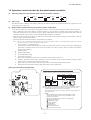
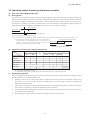
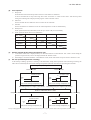
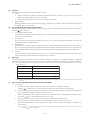
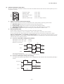
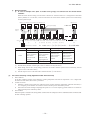
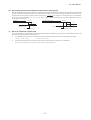
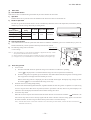
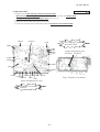
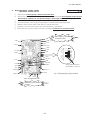
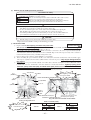
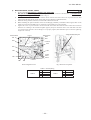
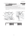
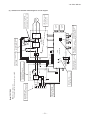
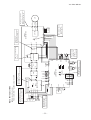
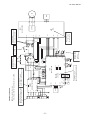
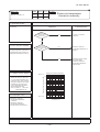
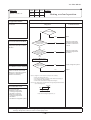
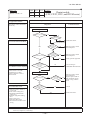
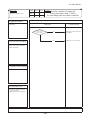
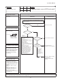
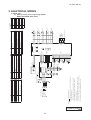
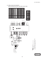
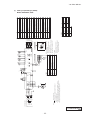
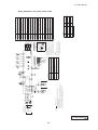
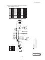
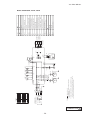
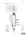
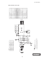
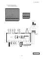
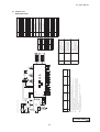
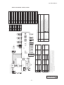
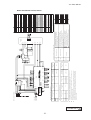
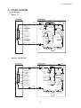
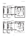
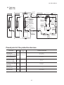
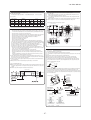
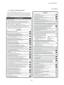
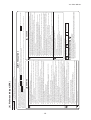
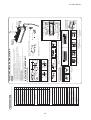
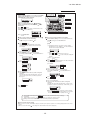
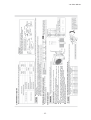
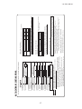
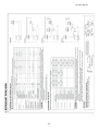
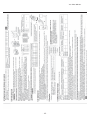
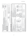
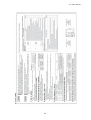
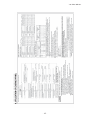
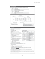
– 106 – Earth 3 Y㧛GN F㧔3.15A㧕 F㧔3.15A㧕 BL 1 WH 3 RD 5 FM I 1 CF I 1 1 M FMI 2 M 5 CFI 2 1 Y㧛GN WH Y㧛GN CNF4 5 WH 5 WH 5 L H UH 9 M 5 3 7 X3 C X1 X2 CNM3 1 X6 Y CNF3 RD CNW0 Notes 1. indicates wiring on site. ޓޓ2. See the wiring diagram of outside unit about the line between inside unit and outside unit. ޓޓ3. Use twin core cable㧔0.3mm2 X2㧕at remote controller line. See spec ޓޓsheet of remote controller in case that the total length is more than 100m. ޓޓ4. Do not put remote controller line alongside power source line. Signal line WH RD 5 BK 4 t° GR CNN WH Power source line 1 2 1 2 3 3 2 BR TB1 BK BK 1 t° BK BL Connecting line between indoor unit and outdoor unit Control PCB t° BK RD GR X4 BK CNH DM BL CNR2 1㨪 M CNR 1 3 WH 1 BK F㧔0.16A㧕 6 t° Th I -A 2 BK BR Y ThI -R3 FS CNI BL WH CNW1 220㨺240V RD ThI -R2 19V Tr I BK ThI -R1 WH WH Y t° Remote controller Thc X Y X Y 3 1 TB2 SW2 CNB WH SW7 SW6 SW5 BK CNW2 24V WH BK RD RD RD BR BR BK Color Marks Mark Color Black BK Blue BL Brown BR Gray GR RD Red WH White Y Yellow Y㧛GN Yellow㧛Green LED 3 LED2 6 XR4 XR2 XR5㧔Remote operation : volt-free contact㧕 XR3 CNT 3 BL 4 5 XR1 2 +1 2 1 Option 㧔Operation㧕 㧔Heating㧕 㧔Compressor ON㧕 㧔Inspection㧕 Remote controller communication address Plural units Master㧛Slave setting LED3 SW2 SW5 Operation check, Drain motor test run عmark Closed-end connector Relay for DM Relay for FM X4 Transform e X1ޓ3,6 r ThermistorާHeat exchanger㧕 ThermistorާReturn air㧕 ThermistorާRemote controller㧕 Terminal blockާSignal line㧕㧔غmark㧕 Terminal blockާPower source㧕㧔غmark㧕 Trl Thl -R1,2,3 Thl -A Thc TB2 TB1 SW7-1 SW6 Indication lamp㧔Red-Inspection㧕 LED2 Model capacity setting Float switch Indication lamp㧔Green-Normal operation㧕 FS Fuse Fan motor㧔with thermostat㧕 Drain motor DM I FMl 1, 2 Conector CNBޓZ F CapacitororfFM CFI 1,2 '10 • PAC-SM-137 Models FDUM100VD, 125VD, 140VD PJR002Z245 B