1
Manual No. '10 • PAC - SM - 137
SERVICE MANUAL
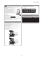
HYPER INVERTER PACKAGED AIR-CONDITIONERS
(Split system, Air to air heat pump type)
CEILING CASSETTE- 4 WAY COMPACT TYPE
Triple type
Twin type
FDTC140VNXTVD
FDTC71VNXPVD
140VSXTVD
100VNXPVD
100VSXPVD
125VNXPVD
125VSXPVD
DUCT CONNECTED-LOW / MIDDLE STATIC PRESSURE TYPE
Triple type
Twin type
Single type
FDUM140VNXTVD
FDUM100VNXPVD
FDUM71VNXVD
140VSXTVD
100VSXPVD
100VNXVD
125VNXPVD
100VSXVD
125VSXPVD
125VNXVD
140VNXPVD
125VSXVD
140VSXPVD
140VNXVD
140VSXVD
CEILING CASSETTE- 4 WAY TYPE
Single type
Twin type
FDT71VNXVD
FDT71VNXPVD
100VNXVD
100VNXPVD
100VSXVD
100VSXPVD
125VNXVD
125VNXPVD
125VSXVD
125VSXPVD
140VNXVD
140VNXPVD
140VSXVD
140VSXPVD
DUCT CONNECTED-HIGH STATIC PRESSURE TYPE
Single type
FDU71VNXVD
100VNXVD
100VSXVD
125VNXVD
125VSXVD
140VNXVD
140VSXVD
CEILING SUSPENDED TYPE
Twin type
Single type
FDEN71VNXPVD
FDEN71VNXVD
100VNXPVD
100VNXVD
100VSXPVD
100VSXVD
125VNXPVD
125VNXVD
125VSXPVD
125VSXVD
140VNXPVD
140VNXVD
140VSXPVD
140VSXVD
Triple type
FDT140VNXTVD
140VSXTVD
Triple type
FDEN140VNXTVD
140VSXTVD
WALL MOUNTED TYPE
Triple type
Twin type
SRK140VNXTZIX
SRK100VNXPZIX
140VSXTZIX
100VSXPZIX
125VNXPZIX
125VSXPZIX
'10 • PAC-SM-137
CONTENTS
1. OUTLINE OF OPERATION CONTROL BY MICROCOMPUTER ................. 3
1.1 Remote controller ................................................................................... 3
1.2 Operation control function by the wired remote controller ................ 5
1.3 Operation control function by the indoor controller ........................... 6
(1) FDTC,FDT,FDEN,FDUM and FDU series ............................................. 6
(2) SRK seies ............................................................................................. 16
1.4 Operation control function by the outdoor controller ........................ 20
2. MAINTENANCE DATA ..................................................................................
2.1 Diagnosing of microcomputer circuit .....................................................
(1) Selfdiagnosis function .............................................................................
(2) Troubleshooting procedure ....................................................................
(3) Troubleshooting at the indoor unit ........................................................
(4) Troubleshooting at the outdoor unit ......................................................
(5) Check of anomalous operation data with the remote controller .............
31
31
31
34
34
40
47
(6) Inspection display of wireless specification model (FDEN,FDT) ............. 48
(7) Power transistor module (including the driver PCB) inspection procedure ......... 49
(8) Inverter checker for diagnosis of inverter output ..................................... 50
(9) Outdoor unit controller failure diagnosis circuit diagram .................................. 51
2.2 Troubleshooting flow ............................................................................... 54
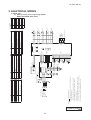
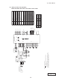
3. ELECTRICAL WIRING ...................................................................................101
(1) Indoor units ............................................................................................101
(2) Outdoor units .........................................................................................110
4. PIPING SYSTEM ............................................................................................113
5. APPLICATION DATA .....................................................................................116
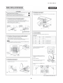
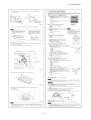
5.1 Installation of indoor unit .......................................................................116
(1) Ceiling cassette-4way compact type (FDTC) ........................................116
(2) Ceiling cassette-4way type (FDT) .........................................................122
(3) Ceiling suspended type (FDEN) ............................................................128
(4) Duct connected-Low / Middle static pressure type (FDUM) ...................132
(5) Duct connected-High static pressure type (FDU) ..................................136
(6) Wall mounted type (SRK) .....................................................................140
-
1-
'10 • PAC-SM-137
5.2 Instullation for wired remote controller ................................................144
5.3 Instullation of outdoor unit ...................................................................150
(1) Model FDC71VNX .................................................................................150
(2) Models FDC100㨪140VNX, 100㨪140VSX ...........................................158
5.4 Electric wiring work installation ...........................................................166
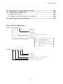
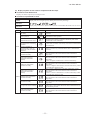
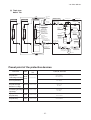
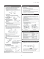
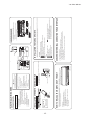
How to read the model name
Example: FDT 125 VNX P
V
Series code
(blank)
: Single type
P : Twin type
T : Triple type
Applicable power source...See the specification
Product capacity
Model name
FDTC
FDT
FDEN
FDUM
FDU
FDC
Example: SRK
125 VNX
: Ceiling cassette-4 way compact type
: Ceiling cassette-4 way type
: Ceiling suspended type
: Duct connected-Low / Middle static
pressure type
: Duct connected-High static pressuret
type
: Outdoor unit
P ZIX
Series code
P : Twin type
T : Triple type
Applicable power source...See the specification
Product capacity
Model name ާ Wall mounted type ި
-
2-
'10 • PAC-SM-137
1. OUTLINE OF OPERATION CONTROL BY MICROCOMPUTER
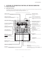
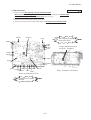
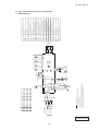
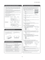
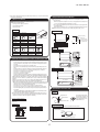
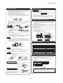
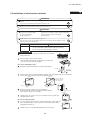
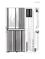
1.1 Remote controller
(1)
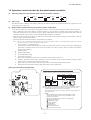
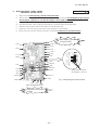
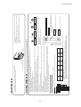
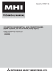
Wired remote controller
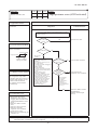
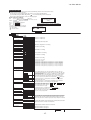
The figure below shows the remote controller with the cover opened. Note that all the items that may be displayed in the liquid
crystal display area are shown in the figure for the sake of explanation
Characters displayed with dots in the liquid crystal display area are abbreviated.
The figure below shows the remote control with the cover opened.
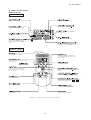
Ventilaion display
Displayed during ventilation operation
Weekly timer display
Displays the settings of the
weekly timer.
Centeal control display
Displayed when the air conditioning system is
controlled by centralized remote control.
Operation setting display area
Displays setting temperature, airflow
volume, operation mode and oparation
message.
Timer operation display
Displays the timer operation setting.
Operation/check indicator light
During oparation: Lit in green
In case of error: Flashing in red
Temperature setting buttons
These buttons are used to set the
temperature of the room.
Operation/stop button
This button is used to operate and stop
the air conditioning system.
Press the button once to operate the
system and press it once again to stop
the system.
Timer button
This button is used to set
the timer mode.
MODE button
This button is used to change the
operation mode.
Timer setting buttons
These buttons are used to set
the timer mode and the time.
FAN SPEED button
This button is used to set the airflow
volume.
VENT button
This button is used to operate external
ventilator.
GRILL button
This button has no function.
When this button is pressed,
(Invalid Operation)
is displayed, but it does not mean a failure.
LOUVER button
This button is used to operate/stop the
swing louver.
Cover
AIR CON No. button
Display the indoor unit number connected to this
remote controller.
SET button
٨
٨
This button is used to fix the setting.
This button is used to set the silent mode.
CHECK button
This button is used at servicing.
RESET button
Press this button while making settings to go back to the
previous operation.
This button is also used to reset the "FILTER CLEANING" display.
(Press it after cleaning the air filter)
٨
TEST button
This button is used during test operation.
٨
䋪㩷All displays are described in the liguid crystal display for explanation.
-
3-
'10 • PAC-SM-137
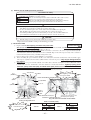
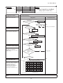
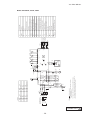
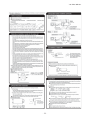
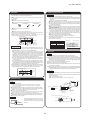
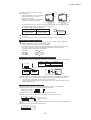
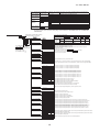
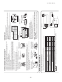
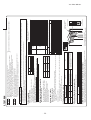
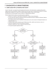
(2) Wireless remote controller
FDEN series only
Indication section
Indicates set temperature.
Indicates the status of swing louver.
Indicates selected operation with
.
Indicates the selected airflow volume
Indicates for two seconds when FILTER
button is pressed.
Indicates when ON-TIMER is set.
Indicates when OFF-TIMER is set.
Indicates the ON-TIMER setting time.
Nothing displayed when ON-TIMER is
not set.
Indicates OFF-TIMER setting time. Indicates the
current time when the OFF-TIMER is not set.
Operation section
Sends signal to the air conditioner.
When this is pressed once, the unit starts to
operate and when this is pressed once again,
it stops operating.
Every time this button is pressed, the mode is
switched as below.
Used to swing the louver.
Used to reset (turn off) the filter sign.
Press the button only after completing
the filter cleaning.
Every time this button is pressed,
as below.
displays switch
Sets ON TIMER operation.
Sets room temperature by pressing
Sets time when setting the time.
Sets OFF TIMER operation.
Used to cancel the TIMER SETTINGS.
Sets current time.
Used to reset the microcomputer.
* All displays are described in the liquid crystal display for explanation
-
4-
or
button.
'10 • PAC-SM-137
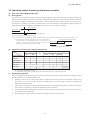
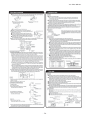
1.2 Operation control function by the wired remote controller
(1)
Switching sequence of the operation mode switches of remote controller
$29
#//,
&!.
(%!4
!54/
(2)
[CPU reset]
(3)
This functions when “CHECK” and “GRILL” buttons on the remote controller are pressed simultaneously. Operation is same
as that of the power supply reset.
[Power failure compensation function]...Electric power supply failure
• This becomes effective if “Power failure compensation effective” is selected with the setting of remote controller function.
• Since it memorizes always the condition of remote controller, it starts operation according to the contents of memory no
sooner than normal state is recovered after the power failure. Although the auto swing stop position and the timer mode are
cancelled, the weekly timer setting is restored with the holiday setting for all weekdays.
After recovering from the power failure, it readjusts the clock and resets the holiday setting for each weekday so that the
setting of weekly timer becomes effective.
• Content memorized with the power failure compensation are as follows.
Note (1) Items, and are memorized regardless whether the power failure compensation is effective or not while the setting of silent mode is cancelled
regardless whether the power failure compensation is effective or not.
At power failure – Operating/stopped
If it had been operating under the off timer mode, sleep timer mode, the state of stop is memorized. (Although the
timer mode is cancelled at the recovery from power failure, the setting of weekly timer is changed to the holiday
setting for all weekdays.)
Operation mode
$LUÀRZYROXPHPRGH
Room temperature setting
Louver auto swing/stop
However, the stop position (4-position) is cancelled so that it returns to Position (1).
“Remote controller function items” which have been set with the remote controller function setting (“Indoor
function items” are saved in the memory of indoor unit.)
Upper limit value and lower limit value which have been set with the temperature setting control
Sleep timer and weekly timer settings (Other timer settings are not memorized.)
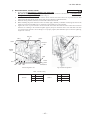
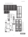
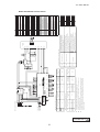
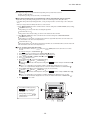
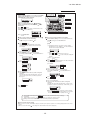
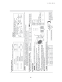
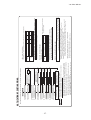
[Parts layout on remote controller PCB]
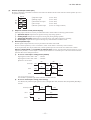
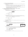
Master/ slave setting when more than one remote controllers are used
A maximum of two remote controllers can be connected to one indoor unit (or one group of indoor units.)
Switch
Indoor units
SW2
SW1
Setting
Contents
M
Master remote controller
S
Slave remote controller
Remote controller cord (no polarity)
SW2
A
Upper
Master
B
Remote controller
SW1 "Master"
親
M
SW1
Remote controller
SW1 "Slave"
Slave
Board
Lower
S
SW1子
Set SW1 to "Slave" for the slave remote controller. It was factory set to "Master" for shipment.
X
Y
Note: The setting "Remote controller thermistor enabled" is only selectable with the master remote
controller in the position where you want to check room temperature.
The air conditioner operation follows the last operation of the remote controller regardless of the
master/ slave setting of it.
Caution
When using multiple remote controllers, the following dispiays or settings
cannot be done with the slave remote controller. It is available only with
the master remote controller.
ޓLouver position setting (set upper or lower limit of swinging range)
ޓSetting indoor unit functions
ޓSetting temperature range
ޓOperation data display
ޓError data display
ޓSilent mode setting
ޓTest operation of drain pump
ޓRemote controller sensor setting
-
5-
'10 • PAC-SM-137
1.3 Operation control function by the indoor controller
(1)
(a)
FDTC, FDT, FDEN, FDUM and FDU series
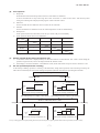
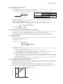
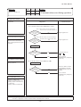
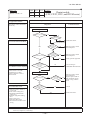
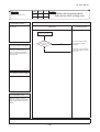
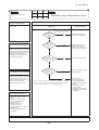
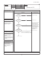
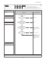
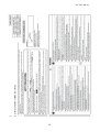
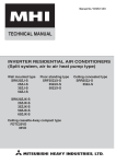
Auto operation
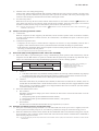
If “Auto” mode is selected by the remote controller, the heating and the cooling are automatically switched according to the
difference between outdoor air temperature and setting temperature and the difference between setting temperature and return
air temperature. (When the switching of cooling mode ¢ heating mode takes place within 3 minutes, the compressor does
not operate for 3 minutes by the control of 3-minute timer.) This will facilitate the cooling/heating switching operation in
intermediate seasons and the adaptation to unmanned operation at stores, etc (ATM corner of bank).
Cooling operation
Heating operation
-3
+3
Room temperature setting temperature
Room temperature (detected with ThI-A) [deg]
Note (1) Room temperature control during auto cooling/auto heating is performed according to the room temperature setting temperature. (DIFF: ±1 deg)
(2) If the indoor heat exchanger temperature rises to 59°C or higher during
Heating operation stopped (cooling)
heating operation, it is switched automatically to cooling operation. In
addition, for 1 hour after this switching, the heating operation is not Heating OK
performed, regardless of the temperature shown at right.
56
59
Indoor heat exchanger temperature (°C)
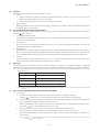
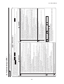
(b)
Operations of functional items during cooling/heating
Cooling
Operation
Functional item
Heating
Thermostat Thermostat
ON
OFF
Fan
Thermostat Thermostat
ON
OFF
Hot start
(Defrost)
Dehumidify
/
Compressor
4-way valve
()
Outdoor unit fan
()
/
Indoor unit fan
/
/
/
/
Louver motor
/
/
/×
/
/
Drain pump (3)
(2)
/
(2)
(2)
Thermostat ON: Thermostat OFF: (2)
/: Turned ON/OFF by the control other than the room temperature control.
Note (1) : Operation : Stop
(2) ON during the drain motor delay control.
(3) Drain pump ON setting may be selected with the indoor unit function setting of the wired remote controller.
(c)
Dehumidifying operation
Return air temperature thermistor [ThI-A (by the remote controller when the remote controller thermistor is enabled)] controls
the indoor temperature environment simultaneously.
1)
Operation is started in the cooling mode. When the difference between the return air temperature and the setting
temperature is 2°C or less, the indoor unit fan tap is brought down by one tap. That tap is retained for 3 minutes after
changing the indoor unit fan tap.
2)
If the return air temperature exceeds the setting temperature by 3°C during defrosting operation, the indoor unit fan tap is
raised. That tap is retained for 3 minutes after changing the indoor unit fan tap.
3)
If the thermostat OFF is established during the above control, the indoor unit fan tap at the thermostat ON is retained so
far as the thermostat is turned OFF.
4)
After stopping the cooling operation, the indoor unit continues to run at Lo for 15 seconds.
-
6-
'10 • PAC-SM-137
(d)
Timer operation
1)
Sleep timer
Set the duration of time from the present to the time to turn off the air-conditioner.
It can be selected from 10 steps in the range from “OFF 1 hour later” to “OFF 10 hours later”. After the sleep timer
setting, the remaining time is displayed with progress of time in the unit of hour.
2)
OFF timer
Time to turn OFF the air-conditioner can be set in the unit of 10 minutes.
3)
ON timer
Time to turn ON the air-conditioner can be set. Indoor temperature can be set simultaneously.
4)
Weekly timer
Timer operation (ON timer, OFF timer) can be set up to 4 times a day for each weekday.
5)
Timer operations which can be set in combination
Item
Item
Sleep timer
OFF timer
ON timer
Weekly timer
Sleep timer
OFF timer
ON timer
Weekly timer
Note (1) : Allowed : Not
(e)
Remote controller display during the operation stop
1)
(f)
“Centralized control ON” is displayed always on the LCD under the “Center/Remote” and “Center” modes during the
operation stop (Power ON). This is not displayed under the “Remote” mode.
2) If this display is not shown under the “Center/Remote” mode, check if the indoor unit power switch is turned on or not.
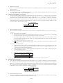
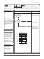
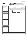
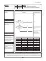
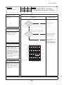
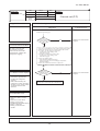
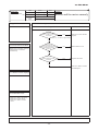
Hot start (Cold draft prevention at heating)
At the startup of heating operation, at resetting of the thermostat, during defrost operation and at returning to heating, the
indoor fan is controlled by the indoor heat exchanger temperature (detected with ThI-R) for preventing the cold draft.
Judgment by heating start thermostat
Thermostat OFF
Thermostat ON
Set airflow volume
Lo
Fan
Lo
Set airflow volume
Fan
OFF
35
25
Indoor heat exchanger temperature (˚C)
35
Indoor heat exchanger temperature (˚C)
Heat exchanger temp. 35˚C or higher, or after 7 minutes
Heat exchanger temp. 35˚C or higher, or after 7 minutes
Normal condition/Set airflow volume
Compressor ON
Compressor OFF
Defrosting start
End of defrosting
Set airflow volume
Lo
Set airflow volume
Fan
OFF
(1)
Fan
Lo
35
45
25
Indoor heat exchanger temperature (˚C)
35
45
Indoor heat exchanger temperature (˚C)
1RWH +HDWLQJSUHSDUDWLRQLVGLVSOD\HGGXULQJWKHKRWVWDUWZKHQWKHFRPSUHVVRULVRSHUDWLQJDQGWKHLQGRRUIDQGRHVQRWSURYLGHWKHVHWDLUÀRZYROXPH
-
7-
'10 • PAC-SM-137
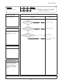
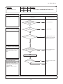
(g)
Hot keep
Hot keep control is performed at the start of the defrost control.
1) Control
a)
(h)
When the indoor heat exchanger temperature (detected with ThI-R1 or R2) drops to 35°C or lower, the speed of
indoor fan is changed to the lower tap at each setting.
b) During the hot keep, the louver horizontal control signal is transmitted.
2) Ending condition
:KHQWKHLQGRRUIDQLVDWWKHORZHUWDSDWHDFKVHWWLQJLWUHWXUQVWRWKHVHWDLUÀRZYROXPHDVWKHLQGRRUKHDWH[FKDQJHU
temperature rises to 45°C or higher.
Fan control during the heating thermostat OFF
When the heating thermostat is turned OFF, the setting of the fan control is selectable using the indoor function of wired remote
controller [
1)
2)
3)
4)
(i)
FAN CONTROL].
Low fan speed (Factory default)
If the indoor heat exchanger temperature drops below 35°C with the heating thermostat OFF, the indoor fan operate at the
lower speed tap at each setting.
Set fan speed
Even if the indoor heat exchanger temperature drops below 35°C with the heating thermostat OFF, the indoor fan
FRQWLQXHVWRUXQDWWKHVHWDLUÀRZYROXPH
Intermittence
If the indoor heat exchanger temperature drops below 35°C with the heating thermostat OFF, the indoor fan operates at
the lower speed tap at each setting and, when the indoor heater exchanger temperature drops below 25°C, the indoor fan
stops for 5 minutes. Then the fan runs at the low speed tap for 2 minutes, and the judgment is made by the thermostat.
Fan OFF
If the indoor heat exchanger temperature drops below 35°C with the heating thermostat OFF, the indoor fan is turned
OFF. The same applies also when the remote controller sensor is effective.
Filter sign
As the operation time (Total ON time of ON/OFF switch) accumulates to 180 hours (1), “FILTER CLEANING” is displayed
on the remote controller. (This is displayed when the unit is in trouble and under the centralized control, regardless of ON/OFF)
1RWH7LPHVHWWLQJIRUWKH¿OWHUVLJQFDQEHPDGHDVVKRZQEHORZXVLQJWKHLQGRRUIXQFWLRQRIZLUHGUHPRWHFRQWUROOHU³),/7(56,*16(7´,WLVVHWDWDWWKH
shipping from factory.)
Filter sign setting
Function
TYPE 1
Setting time: 180 hrs (Factory default)
TYPE 2
Setting time: 600 hrs
TYPE 3
Setting time: 1,000 hrs
TYPE 4
Setting time: 1,000 hrs (Unit stop) (2)
(2) After the setting time has elapsed, the “FILTER CLEANING” is displayed and, after operating for 24 hours further (counted also during the stop), the
unit stops.
(j)
Auto swing control [Applicable model: FDTC, FDT and FDEN]
1)
Louver control
a) Press the “LOUVER” button to operate the swing louver when the air conditioner is operating.
“SWING
E
” is displayed for 3 seconds and then the swing louver moves up and down continuously.
7R¿[WKHVZLQJORXYHUDWDSRVLWLRQSUHVVRQHWLPHWKH³/289(5´EXWWRQZKLOHWKHVZLQJORXYHULVPRYLQJVRWKDW
four stop positions are displayed one after another per second.
When a desired stop position is displayed, press the “LOUVER” button again. The display stops, changes to show
the “STOP 1
c)
” for 5 seconds and then the swing louver stops.
Louver operation at the power on with a unit having the louver 4-position control function
The louver swings one time automatically (without operating the remote controller) at the power on.
This allows inputting the louver motor (LM) position, which is necessary for the microcomputer to recognize the
louver position.
Note (1) If you press the “LOUVER” button, the swing motion is displayed on the louver position LCD for 10 second. The display changes to the
” display 3 seconds later.
“SWING
-
8-
'10 • PAC-SM-137
2)
Automatic louver level setting during heating
3)
At the hot start with the heating thermostat OFF, regardless whether the auto swing switch is operated or not (auto swing
or louver stop), the louver takes the level position (In order to prevent the cold start). The louver position display LCD
continues to show the display which has been shown before entering this control.
Louver-free stop control
When the louver-free stop has been selected with the indoor function of wired remote controller “
POSITION”, the
louver motor stops when it receives the stop signal from the remote controller. If the auto swing signal is received from
the remote controller, the auto swing will start from the position where it was before the stop.
Note (1) When the indoor function of wired remote controller “
POSITION” has been switched, switch also the remote control function “
POSITION” in the same way.
(k)
Compressor inching prevention control
1)
3-minute timer
When the compressor has been stopped by the thermostat, remote controller operation switch or anomalous condition,
2)
its restart will be inhibited for 3 minutes. However, the 3-minute timer is invalidated at the power on the electric power
source for the unit.
3-minute forced operation timer
• Compressor will not stop for 3 minutes after the compressor ON. However, it stops immediately when the unit is
stopped by means of the ON/OFF switch or by when the thermister turned OFF the change of operation mode.
• If the thermostat is turned OFF during the forced operation control of heating compressor, the louver position (with the
auto swing) is returned to the level position.
Note (1) The compressor stops when it has entered the protective control.
(l)
Drain motor (DM) control [Applicable model: FDTC, FDT and FDUM]
1)
Drain motor (DM) is operated during the cooling or dehumidifying mode operations and simultaneously with the
compressor ON. The DM continues to operate for 5 minutes after the operation stop, anomalous stop, thermostat stop or
when it was switched from the cooling and dehumidifying operations to the fan or heating operation.
Indoor unit operation mode
Stop
(1)
Cooling
Dehumidifying
Compressor ON
Compressor OFF
a)
Fan (2)
Control A
Heating
Note (1) Including the stop from the cooling, dehumidifying, fan
and heating, and the anomalous stop
(2) Including the “Fan” operation according to the
mismatch of operation modes
Control B
Control A
L
b)
,IWKHÀRDWVZLWFKGHWHFWVDQ\DQRPDORXVGUDLQLQJFRQGLWLRQWKHXQLWVWRSVZLWKWKHDQRPDORXVVWRSGLVSOD\V
E9) and the drain pump starts. After detecting the anomalous condition, the drain motor continues to be ON.
LL ,WNHHSVRSHUDWLQJZKLOHWKHÀRDWVZLWFKLVGHWHFWLQJWKHDQRPDORXVFRQGLWLRQ
Control B
,I WKH ÀRDW VZLWFK GHWHFWV DQ\ DQRPDORXV GUDLQ FRQGLWLRQ WKH GUDLQ PRWRU LV WXUQHG 21 IRU PLQXWHV DQG DW VHFRQGVDIWHUWKHGUDLQPRWRU2))LWFKHFNVWKHÀRDWVZLWFK,ILWLVQRUPDOWKHXQLWLVVWRSSHGXQGHUWKHQRUPDO
mode or, if there is any anomalous condition, E9 is displayed and the drain motor is turned ON. (The ON condition
is maintained during the drain detection.)
2) Drain motor (DM) interlock control
a) Start conditions
Depending on the function setting by the remote controller, the drain motor is turned ON under either one of the
following conditions.
i) During heating mode operation (Both the thermostat ON/OFF)
ii) During heating mode operation (Both the thermostat ON/OFF) + Fan operation
iii) Fan operation
b) End conditions
The drain motor is turned OFF 5 minutes after the stop of operations i) to iii) above.
(m) Operation check/drain pump test run operation mode
1)
2)
If the power is turned on by the dip switch (SW7-1) on the indoor PCB when electric power source is supplied, it enters the
mode of operation check/drain pump test run. It is ineffective (prohibited) to change the switch after turning power on.
When the communication with the remote controller has been established within 60 seconds after turning power on by the
dip switch (SW7-1) ON, it enters the operation check mode. Unless the remote controller communication is established, it
enters the drain pump test run mode.
Note (1) To select the drain pump test run mode, disconnect the remote controller connector (CNB) on the indoor PCB to shut down the remote controller
communication.
-
9-
'10 • PAC-SM-137
3)
(n)
Operation check mode
There is no communication with the outdoor unit but it allows performing operation in respective modes by operating the
remote controller.
4) Drain pump test run mode
As the drain pump test run is established, the drain pump only operates and during the operation protective functions by
the microcomputer of indoor unit become ineffective.
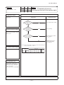
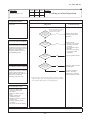
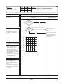
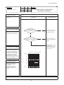
Cooling, dehumidifying frost protection
1)
To prevent frosting during cooling mode or dehumidifying mode operation, the of compressor speed is reduced if
the indoor heat exchanger temperature (detected with ThI-R) drops to 1.0 °C or lower at 4 minutes after the start of
compressor operation. If the indoor unit heat exchanger temperature is 1.0 °C or lower after 1 minutes, the compressor
speed is reduced further. If it becomes 2.5 °C or higher, the control terminates. When the indoor heat exchanger
temperature has become as show below after reducing the compressor speed, it is switched to the fan operation. For the
selection of indoor fan speed, refer to item 2).
Cooling operation
Fan operation
1.0
10
Indoor heat exchanger temperature (°C)
2)
Selection of indoor fan speed
If it enters the frost prevention control during cooling operation (excluding dehumidifying), the indoor unit fan speed is
switched.
(a) In cases of FDUM, FDU and FDEN
i) When the indoor unit return air temperature (detected with ThI-A) is 23°C or lower, this control is invalidated
and, as 2 hours elapse after starting the frost prevention control, it is terminated.
ii) If it is detected again within 15 minutes from the start of frost prevention control, the indoor fan speed is raised
by 1 tap to increase the indoor unit fan speed. If it is detected within further 15 minutes, the indoor unit fan
speed is raised by 1 tap more.
Note (1) Indoor unit fan speed can be increased by up to 2 taps.
b)
iii) “ FAN SPEED SW VALID/INVALID” of this control is selectable with the function setting of remote
controller.
In the case of FDT and FDTC
i) When the indoor return air detection temperature (detected with ThI-A) is 23°C or higher and the indoor heat
exchanger temperature (detected with ThI-R) detects the compressor frequency drop start temperature A°C+1°C,
of indoor unit fan speed is increased by 20rpm.
ii) If the phenomenon of i) above is detected again after the acceleration of indoor unit fan, indoor unit fan speed
is increased further by 20rpm.
Note (1) Indoor unit fan speed can be increased by up to 2 taps.
• Compressor frequency drop start temperature
Symbol
Item
Temperature - Low (Factory default)
Temperature - High
A
1.0
2.5
Note (1) Frost prevention temperature setting can be selected with the indoor unit function setting of the wired remote controller.
(o)
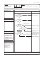
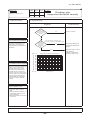
Heating overload protection
1)
If the indoor heat exchanger temperature (detected with ThI-R) at 63°C or higher is detected for 2 seconds continuously,
the compressor stops. When the compressor is restarted after a 3-minute delay, if a temperature at 63°C or higher is
detected for 2 seconds continuously within 60 minutes after initial detection and if this is detected 5 times consecutively,
the compressor stops with the anomalous stop (E8). Anomalous stop occurs also when the indoor heat exchanger
temperature at 63°C or higher is detected for 6 minutes continuously.
Compressor OFF
Compressor ON
56
63
Indoor heat exchanger temperature (°C)
2)
Indoor unit fan speed selection
If, after second detection of heating overload protection up to fourth, the indoor fan is set at Me and Lo taps when the
compressor is turned ON, the indoor fan speed is increased by 1 tap.
-
10 -
'10 • PAC-SM-137
(p)
Anomalous fan motor [In case of FDT, FDTC only]
(q)
After starting the fan motor, if the fan motor speed is 200rpm or less is detected for 30 seconds continuously and 4 times within
60 minutes, then fan motor stops with the anomalous stop (E16).
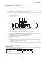
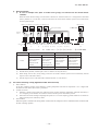
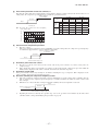
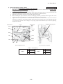
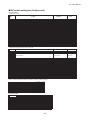
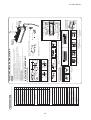
Plural unit control – Control of 16 units group by one remote controller
1)
Function
One remote controller switch can control a group of multiple number of unit (Max. 16 indoor units). “Operation mode”
which is set by the remote controller switch can operate or stop all units in the group one after another in the order of unit
No.(1). Thermostat and protective function of each unit function independently.
Note (1) Unit No. is set by SW2 on the indoor unit control PCB. Unit No. setting by SW2 is necessary for the indoor unit only. In cases of the twin, triple
and double-twin specification, it is necessary set for the master and the slave units. This can be selected by SW5. (All are set for the master unit at
the shipping from factory.)
SW2: For setting of 0 – 9, A – F
SW5: For setting of master and slave units
(See table shown at right.)
SW5 setting
Switch
SW5-1
SW5-2
Master unit
OFF
OFF
Slave unit a
OFF
ON
Slave unit b
ON
OFF
Slave unit c
ON
ON
Unit
Outdoor unit
Signal wiring
between outdoor unit
and indoor units
Refrigerant piping
0
1
2
4
3
(Master unit)
4
(Slave unit a)
4
(Slave unit b)
4
(Slave unit c)
F
Indoor unit
R
Remote controller wiring
Remote controller
(2) Unit No. may be set at random unless duplicated, it should be better to set orderly like 0, 1, 2…, F to avoid mistake.
2)
(r)
Display to the remote controller
a) Center or each remote controller basis, heating preparation: the youngest unit No. among the operating units in the
remote mode (or the center mode unless the remote mode is available) is displayed.
b) Inspection display, filter sign: Any of unit that starts initially is displayed.
c) Confirmation of connected units
Pressing “AIR CON No.” button on the remote controller displays the indoor unit address. If “S” “T” button is
pressed at the next, it is displayed orderly starting from the unit of youngest No.
d) In case of anomaly
i) If any anomaly occurs on a unit in a group (a protective function operates), that unit stops with the anomalous
stop but any other normal units continue to run as they are.
ii) Signal wiring procedure
Signal wiring between indoor and outdoor units should be made on each unit same as the normal wiring.
For the group control, lay connect with sires wiring between rooms using terminal blocks (X, Y) of remote
controller.
Connect the remote controller communication wire separately from the power supply wire or wires of other
electric devices (AC220V or higher).
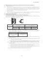
High ceiling control
In the case of indoor unit installed in a higher ceiling room, the airflow volume mode control can be changed with the wired
remote controller indoor unit function “FAN SPEED SET”.
Indoor unit airflow setting
UH - Hi - Me - Lo Hi - Me - Lo Hi - Lo Hi - Me
STANDARD
FAN SPEED SET
HIGH SPEED1, 2 UH - UH - Hi - Me UH - Hi - Me UH - Me UH - Hi
Fan tap
Note (1) Factory default is Standard.
(2) At the hot-start and heating thermostat OFF, or other, the indoor unit fan is operated at the low speed tap of each setting.
-
11 -
'10 • PAC-SM-137
(s)
Abnormal temperature thermistor (return air/indoor heat exchanger) wire/short-circuit detection
1)
Broken wire detection
When the return air temperature thermistor detects -50°C or lower or the heat exchanger temperature thermistor detect
-50°C or lower for 5 seconds continuously, the compressor stops. After a 3-minute delay, the compressor restarts but,
if it is detected again within 60 minutes after the initial detection for 6 minutes continuously, stops again (the return air
temperature thermistor: E7, the heat exchanger temperature thermistor: E6).
2)
Short-circuit detection
If the heat exchanger temperature thermistor detects 70°C or higher for 5 seconds continuously at 2 minutes and 20
seconds after the compressor ON during cooling operation, the compressor stops (E6).
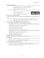
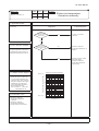
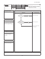
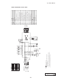
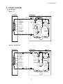
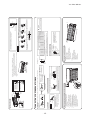
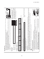
(t)
Operation permission/prohibition
(In case of adopting card key switches or commercially available timers)
When the indoor function setting of wired remote controller for “Operation permission/prohibition” is changed from “Invalid
(Factory default)” to “ Valid”, following control becomes effective.
1
2
CnT
Blue
12V
Optional
XR1
3
4
5
XR2
XR3
Card key
switch
XR5
XR4
6
XR5
Normal operation
(Factory default)
CnT-6
*1
Operation permission/prohibition mode
“Valid” (Local setting)
ON
OFF
ON
OFF
Operation
Stop
Operation
permission*1
Operation prohibition
(Unit stops)
Only the “LEVEL INPUT” is acceptable for external input, however when the indoor function setting of
“Level input (Factory default)” or “Pulse input” is selected by the function for “External input” of the wired remote
controller, operation status will be changed as follows.
*(1)
*(2)
(3)
In case of “Level input” setting
In case of “Pulse input” setting
Unit operation from the wired
remote controller becomes
available*(1)
Unit starts operation
*(2)
In case that “Operation permission/prohibition mode” setting is “Valid” and “External input” setting is “Level
input (Factory default)”;
① When card key switch is ON (CnT-6 ON: Operation permission), start/stop operation of the unit from the
wired remote controller becomes available.
② When card key switch is OFF (CnT-6 OFF: Operation prohibition), the unit stops operation in conjunction
with OFF signal, and start/stop operation of the unit from the wired remote controller becomes not available.
In case that “Operation permission/prohibition mode” setting is “Valid” and “External input” setting is “Pulse
input (Local setting)”;
① When card key switch is ON (Operation permission), the unit starts operation in conjunction with ON signal.
and also start/stop operation of the unit from the wired remote controller becomes available.
② When card key switch is OFF (Operation prohibition), the unit stops operation in conjunction with OFF signal, and
start/stop operation of the unit from the wired remote controller becomes not available.
This function is invalid only at “Center mode” setting done by central controller.
-
12 -
'10 • PAC-SM-137
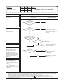
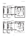
(u)
External input/output control (CnT)
Be sure to connect the wired remote controller to the indoor unit. Without wired remote controller remote operation by CnT is
not possible to perform.
1
2
CnT
Blue
12V
Optional
①Operation output
XR1
②Heating output
(CnT-3: XR2)
③Thermostat ON output
(CnT-4: XR3)
④Error output
(CnT-5: XR4)
⑤Remote operation input
(CnT-6: No-voltage contactor)
3
4
5
XR2
XR3
XR4
6
(CnT-2: XR1)
XR5
1)
2)
Output for external control (remote display)
Following output connectors (CnT) are provided on the indoor control PCB for monitoring operation status.
① Operation output: Outputs DC12V signal for driving relay during operation
② Heating output: Outputs DC12V signal for driving relay during heating operation
③ Thermostat ON output: Outputs DC12V signal for driving relay when compressor is operating.
④ Error output: Outputs DC12V signal for driving relay when anomalous condition occurs.
Remote operation input
Remote operation input connector (CnT-6) is provided on the indoor control PCB.
However remote operation by CnT-6 is not effective, when “Center mode” is selected by center controller.
In case of plural unit (twin, triple, double twin), remote operation input to CnT-6 on the slave indoor unit is invalid.
Only the “LEVEL INPUT” is acceptable for external input, however when the indoor function setting of “Level
input (Factory default)” or “Pulse input” is selected by the function for “External input” of the wired remote controller,
operation status will be changed as follows.
a) In case of “Level input” setting (Factory default)
,QSXWVLJQDOWR&Q7LV2))ĺ21««XQLW21
,QSXWVLJQDOWR&Q7LV21ĺ2))««XQLW2))
Operation is not inverted.
ON
CnT-6 input
ON
OFF
OFF
OFF
ON
Unit A
ON
OFF
OFF
OFF
ON
ON
Unit B
OFF
OFF
Note: The latest operation has priority
b)
It is available to operate/stop by remote controller or center controller
In case of “Pulse input” setting (Local setting)
,WLVHIIHFWLYHRQO\ZKHQWKHLQSXWVLJQDOWR&Q7LVFKDQJHG2))ĺ21DQGDWWKDWWLPHXQLWRSHUDWLRQ>212))@LV
inverted.
ON
ON
CnT-6 input OFF
OFF
OFF
ON
Unit A
OFF
OFF
ON
ON
Unit B
OFF
-
13 -
'10 • PAC-SM-137
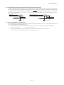
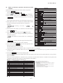
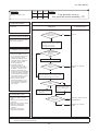
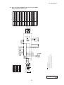
3)
Remote operation
a) In case of multiple units (Max. 16 indoor units group) are connected to one wired remote
controller
When the indoor function setting of wired remote controller for “External control set” is changed from “Individual
(Factory default)” to “ For all units”, all units connected in one wired remote controller system can be controlled by
external operation input.
Outdoor unit Outdoor unit Outdoor unit Outdoor unit
①
②
③
④
123
123
Signal &
Power
123
123
123
123
Outdoor unit
Ⓝ
Refrigerant piping
123
123
XY
Indoor unit
①
XY
Cn
External
input
123
XY
XY
Indoor unit
②
Indoor unit
③
Wired remote controller
123
XY
XY
Indoor unit Indoor unit
④䇭(master) ④䇭(slave)
CnT-6
Only the unit
directly connected
to the remote
controller can be
operated.
Unit ① only
123
123
XY
XY
XY
Indoor unit
④䇭(slave)
Indoor unit
④䇭(slave)
Indoor unit
Ⓝ
Ex. Indoor units = ①+②+③+④x4+……Ⓝ ≦16 units
Individual operation (Factory default)
ON
123
All units operation (Local setting)
OFF
Only the unit
directly connected
to the remote
controller can be
stopped opeartion.
Unit ① only
ON
All units in one
remote controller
system can be
operated.
Units ①−Ⓝ
OFF
All units in one
remote controller
system can be
stopped operation.
Units ①−Ⓝ
When more than one indoor unit (Max. 16 indoor units) are connected in one wired remote controller system:
(1)
With the factory default, external input to CnT-6 is effective for only the unit ①.
(2)
When setting “For all unit” (Local setting), all units in one remote controller system can be controlled by external
input to CnT-6 on the indoor unit ①.
(3)
(v)
External input to CnT-6 on the other indoor unit than the unit ① is not effective.
Fan control at heating startup (Applicable model: FDTC and FDT)
1)
2)
3)
Start conditions
At the start of heating operation, if the difference of setting temperature and return air temperature is 5°C or higher after
the end of hot start control, this control is performed.
Contents of control
a) Sampling is made at each minute and, when the indoor unit heat exchanger temperature (detected with ThI-R) is
37°C or higher, present number of revolutions of indoor unit fan speed is increased by 10min-1.
b) If the indoor unit heat exchanger temperature drops below 37°C at next sampling, present number of revolutions of
indoor unit fan speed is reduced by 10min-1.
End conditions
,QGRRUIDQVSHHGLVUHGXFHGWRWKHVHWWLQJDLUÀRZYROXPHZKHQWKHFRPSUHVVRU2))LVHVWDEOLVKHGDQGDWPLQXWHVDIWHU
the start of heating operation.
-
14 -
'10 • PAC-SM-137
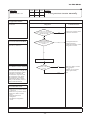
(w)
Room temperature detection temperature compensation during heating
:LWKWKHVWDQGDUGVSHFL¿FDWLRQWKHFRPSUHVVRULVWXUQHG212))ZLWKWKHWKHUPRVWDWVHWWLQJWHPSHUDWXUH:KHQWKHWKHUPRVWDW
is likely to turn OFF earlier because the unit is installed at the ceiling where warm air tends to accumulate, the setting can be
changed with the wired remote controller indoor unit function “
”. The compressor and the heater are turned ON/OFF
at one of the setting temperature +3, +2 or +1°C in order to improve the feeling of heating. The setting temperature, however,
has the upper limit of 30°C.
Standard
Operation
Compressor
When it is set at +3°C
Compressor
Operation
Stop
-1
Stop
+1
+2
Setting temperature
Room temperature (deg)
(x)
+4
Setting temperature
Room temperature (deg)
Return air temperature compensation
This is the function to compensate the deviation between the detection temperature by the return air temperature thermistor and
the measured temperature after installing the unit.
1) It is adjustable in the unit of 0.5°C with the wired remote controller indoor unit function “RETURN AIR TEMP”.
• +1.0°C, +1.5°C, +2.0°C
2)
• -1.0°C, -1.5°C, -2.0°C
Compensated temperature is transmitted to the remote controller and the compressor to control them.
Note (1) The detection temperature compensation is effective on the indoor unit thermistor only.
-
15 -
'10 • PAC-SM-137
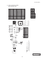
(2)
SRK series
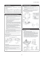
(a) Unit ON/OFF button
If the remote control is malfunctioning, this button may be used to turn the unit on and off.
1)
Operation
Push the button once to place the unit in the automatic mode. Push it once more to turn the unit off.
2)
Details of operation
The unit will go into the automatic mode in which it automatically determines, from room temperature (as detected by sensor),
whether to go into the cooling, thermal dry or heating modes.
Function Roon temperature
Fan speed Swing contral Timer switch
setting
Operation mode
Cooling
About 24ºC
Thermal dry
About 25ºC
Heating
About 26ºC
Auto
Auto
Continuous
Unit ON/OFF button
(b) Auto restart function
1)
Auto restart function records the operational status of the air-conditioner immediately prior to be switched off by a power cut,
and then automatically resumes operations after the power has been restored.
2)
The following settings will be cancelled:
Jumper wire (J170)
• Timer settings
Notes (1) Auto restart function is set at on when the air-conditioner is shipped from the factory. Consult
with your dealer if this function needs to be switched off.
(2) When power failure occurs, the timer setting is cancelled. Once power is resumed, reset the timer.
(3) If the jumper wire (J170) “AUTO RESTART” is cut, auto restart is disabled. (See the diagram at right)
(c)
Auto swing control
1)
Louver control
a)
Press the “LOUVER” button to operate the swing louver when the air conditioner is operating.
“AUTO
E
” is displayed for 3 seconds and then the swing louver moves up and down continuously.
7R¿[WKHVZLQJORXYHUDWDSRVLWLRQSUHVVRQHWLPHWKH³/289(5´EXWWRQZKLOHWKHVZLQJORXYHULVPRYLQJVRWKDW
four stop positions are displayed one after another per second.
When a desired stop position is displayed, press the “LOUVER” button again. The display stops, changes to show
the “STOP 1
2)
” for 5 seconds and then the swing louver stops.
Automatic louver level setting during heating
At the hot start with the heating thermostat OFF, regardless whether the auto swing switch is operated or not (auto swing
or louver stop), the louver takes the level position (In order to prevent the cold start). The louver position display LCD
continues to show the display which has been shown before entering this control.
3)
Louver-free stop control
When the louver-free stop has been selected with the indoor function of wired remote controller “
POSITION”, the
louver motor stops when it receives the stop signal from the remote controller. If the auto swing signal is received from
the remote controller, the auto swing will start from the position where it was before the stop.
Note (1) When the indoor function of wired remote controller “Louver control setting” has been switched, switch also the remote control function “
POSITION” in the same way.
-
16 -
'10 • PAC-SM-137
(d)
Timer operation
1) Timer
Set the duration of time from the present to the time to turn off the air-conditioner.
It can be selected from 10 steps in the range from “OFF 1 hour later” to “OFF 10 hours later”. After the clock timer
setting, the remaining time is displayed with progress of time in the unit of hour.
2) OFF timer
Time to turn OFF the air-conditioner can be set in the unit of 10 minutes.
3) ON timer
Time to turn ON the air-conditioner can be set. Indoor temperature can be set simultaneously.
4) Weekly timer
Timer operation (ON timer, OFF timer) can be set up to 4 times a day for each weekday.
5) Timer operations which can be set in combination
Item
Item
Timer
OFF timer
ON timer
Weekly timer
Timer
OFF timer
ON timer
Weekly timer
Note (1) : Allowed : Not
(e)
Remote controller display during the operation stop
1) “Centralized control ON” is displayed always on the LCD under the “Center/Remote” and “Center” modes during the
operation stop (Power ON). This is not displayed under the “Remote” mode.
2) If this display is not shown under the “Center/Remote” mode, check if the indoor unit power switch is turned on or not.
(f)
Outline of heating or cooling operation
1) Operation of major functional components in heating mode
Heating
2)
Thermostat ON
Thermostat OFF
Failure
Compressor
ON
OFF
OFF
Indoor fan motor
ON
Outdoor fan motor
ON
OFF
OFF
4-way valve
ON
ON
OFF
(3 minutes ON)
ON(HOT KEEP)
OFF
Operation of major functional components in Cooling mode
Cooling
(g)
Thermostat ON
Thermostat OFF
Failure
Compressor
ON
OFF
OFF
Indoor fan motor
ON
ON
OFF
Outdoor fan motor
ON
OFF
OFF
(few minutes ON)
4-way valve
OFF
OFF
OFF
Frost prevention control
1) Operating conditions
a) Indoor heat exchanger temperature (Th2) is lower than 5ºC.
b) 5 minutes after reaching the compressor command speed except 0 rps.
2) Detail of anti-frost operation
Indoor heat exchanger
temperature
Item
Lower limit speed
5°C or lower
2.5°C or lower
25 rps
0rps
Protects the fan tap just before
Indoor fan
Depends on operation mode
Outdoor fan
4-way valve
Depends on operation mode
OFF
frost prevention control
Depends on stop mode
Compressor
command
speed
Lower
limit
speed
0 rps
2.5
Notes (1) When the indoor heat exchanger temperature is in the range of 2.5~5 ºC, the speed is reduced by 4 rps at each 20 seconds.
(2) When the temperature is lower than 2.5 ºC, the compressor is stopped.
(3) When the indoor heat exchanger temperature is in the range of 5~8 ºC, the compressor command speed is been maintained.
-
17 -
5
8
Indoor heat exchanger
temperature (C)
'10 • PAC-SM-137
5HVHWFRQGLWLRQV:KHQHLWKHURIWKHIROORZLQJFRQGLWLRQLVVDWLV¿HG
a) The indoor heat exchanger temperature (Th2) is 8ºC or higher.
b) The compressor command speed is 0 rps.
(h)
Indoor fan motor protection
When the air conditioner is operating and the indoor fan motor is turned ON, if the indoor fan motor has operated at 300 rpm or
XQGHUIRUPRUHWKDQVHFRQGVWKHXQLWHQWHUV¿UVWLQWKHVWRSPRGHDQGWKHQVWRSVWKHHQWLUHV\VWHP
(i)
Serial signal transmission error protection
(a) Purpose: Prevents malfunction resulting from error on the indoor l outdoor signals.
(b) Detail of operation: If the compressor is operating and a serial signal cannot be received from the indoor control with outdoor
control having serial signals continues for 7 minute and 35 seconds, the compressor is stopped. After the
compressor has been stopped, it will be restarted after the compressor start delay if a serial signal can
be received again from the indoor control.
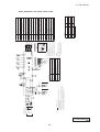
(j)
Plural unit control – Control of 16 units group by one remote controller
1)
Function
One remote controller switch can control a group of multiple number of unit (Max. 16 indoor units). “Operation mode”
which is set by the remote controller switch can operate or stop all units in the group one after another in the order of unit
No.(1). Thermostat and protective function of each unit function independently.
Note (1) Unit No. is set by SW1 on the interface PCB. Unit No. setting by SW1 is necessary for the interface only. In cases of the twin and triple
VSHFL¿FDWLRQLWLVQHFHVVDU\VHWIRUWKHPDVWHUDQGWKHVODYHXQLWV7KLVFDQEHVHOHFWHGE\6:$OODUHVHWIRUWKHPDVWHUXQLWDWWKHVKLSSLQJ
from factory.)
SW1: For setting of 0 – 9, A – F
SW3: For setting of master and slave units
(See table shown at right.)
SW3 setting (For interface PCB)
Switch
SW3-1
SW3-2
Master
OFF
OFF
Stave1
OFF
ON
Stave2
ON
OFF
Unit
Outdoor unit
Signal wiring
between outdoor unit
and indoor units
Refrigerant piping
(Master unit)
Indoor unit
Connection cable
Interfase kit
0
R
1
2
3
(Slave unit 1)
(Slave unit 2)
4
5
6
(Master)
(Slave 1)
(Slave 2)
F
Remote controller wiring
Remote controller
8QLW1RPD\EHVHWDWUDQGRPXQOHVVGXSOLFDWHGLWVKRXOGEHEHWWHUWRVHWRUGHUO\OLNH«)WRDYRLGPLVWDNH
2)
Display to the remote controller
a) Center or each remote controller basis, heating preparation: the youngest unit No. among the operating units in the
remote mode (or the center mode unless the remote mode is available) is displayed.
b) Inspection display: Any of unit that starts initially is displayed.
F &RQ¿UPDWLRQRIFRQQHFWHGXQLWV
Pressing “AIR CON No.” button on the remote controller displays the indoor unit address. If “S” “T” button is
pressed at the next, it is displayed orderly starting from the unit of youngest No.
-
18 -
'10 • PAC-SM-137
d)
(k)
In case of anomaly
i) If any anomaly occurs on a unit in a group (a protective function operates), that unit stops with the anomalous
stop but any other normal units continue to run as they are.
ii) Signal wiring procedure
Signal wiring between indoor and outdoor units should be made on each unit same as the normal wiring. For
the group control, lay connect with sires wiring between rooms using terminal blocks (X, Y) of interface kit.
Connect the remote controller communication wire separately from the power supply wire or wires of other
electric devices (AC220V or higher).
Filter sign
As the operation time (Total ON time of ON/OFF switch) accumulates to 180 hours (1), “Filter cleaning” is displayed on the
remote controller. (This is displayed when the unit is in trouble and under the centralized control, regardless of ON/OFF)
1RWH7LPHVHWWLQJIRUWKH¿OWHUVLJQFDQEHPDGHDVVKRZQEHORZXVLQJWKHLQGRRUIXQFWLRQRIZLUHGUHPRWHFRQWUROOHU³),/7(56,*16(7´,WLVVHWDWDWWKH
shipping from factory.)
Filter sign setting
Function
Setting 1
Setting time: 180 hrs (Factory default)
Setting 2
Setting time: 600 hrs
Setting 3
Setting time: 1,000 hrs
Setting 4
Setting time: 1,000 hrs (Unit stop) (2)
(2) After the setting time has elapsed, the “FILTER CLEANING” is displayed and, after operating for 24 hours further (counted also during the stop), the unit
stops.
-
19 -
'10 • PAC-SM-137
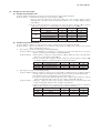
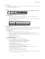
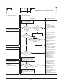
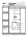
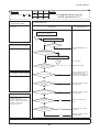
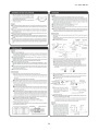
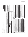
1.4 Operation control function by the outdoor controller
(1)
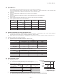
Determination of compressor speed (frequency)
Required frequency
(a)
Cooling/dehumidifying operation
Unit: rps
Model
Max. required
frequency
71
100
125
140
Indoor unit air flow “P-Hi”, “Hi”
88
75
95
95
Indoor unit air flow “Me”, “Lo”
80
60
60
70
20
20
20
20
71
100
125
140
Indoor unit air flow “P-Hi”, “Hi”
112
120
120
120
Indoor unit air flow “Me”, “Lo”
90
60
70
70
20
20
20
20
Min. required frequency
(b)
Heating operation
Unit: rps
Model
Max. required
frequency
Min. required frequency
(c)
(d)
If “Silent mode start” signal is received from the remote controller, the maximum required frequency becomes same as
when the indoor air flow is set at “Lo”.
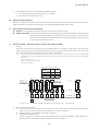
Max. required frequency under high outdoor air temperature in cooling mode
Maximum required frequency is selected according to the outdoor air temperature (Tho-A).
Unit: rps
Model
Outdoor air temperature is
40°C or higher
Outdoor air temperature is
46°C or higher
Max. required
frequency
(e)
71
100
125
140
76
75
75
75
62
75
70
70
Max. required frequency under outdoor air temperature in heating mode
Maximum required frequency is selected according to the outdoor air temperature (Tho-A).
Unit: rps
Model
Outdoor air temperature is
18°C or higher
Max. required
frequency
(f)
(h)
(2)
100
125
140
76
60
80
85
Selection of max. required frequency by heat exchanger temperature
1) Maximum required frequency is selected according to the outdoor unit heat exchanger temperature (Tho-R) during
cooling/dehumidifying or according to the indoor unit heat exchanger temperature (ThI-R) during heating mode.
2) When there are 3 indoor unit heat exchanger temperatures (ThI-R), whichever the highest applies,
Unit: rps
Max. required
frequency
(g)
71
Model
Cooling/
dehumidifying
Heating
Outdoor unit heat exchanger
temperature is 56°C or higher
Indoor unit heat exchanger
temperature is 56°C or higher
71
100
125
140
–
–
–
–
–
100
100
100
When any of the controls from (a) to (f) above may duplicate, whichever the smallest value among duplicated controls is
taken as the maximum required frequency.
During heating, it is operated with the maximum required frequency until the indoor unit heat exchanger temperature
becomes 40°C or higher.
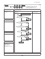
Compressor start control
(a)
(b)
Compressor starts upon receipt of the thermostat ON signal from the indoor unit.
However, at initial start after turning the power supply breaker, it may enter the standby state for maximum 30 minutes
(“
PREPARATION” is displayed on the remote controller) in order to prevent the oil loss in the compressor.
If the cooling/dehumidifying/heating operation is selected from the remote controller when the outdoor unit is in the
standby state, “
PREPARATION” is displayed for 3 seconds on the remote controller.
-
20 -
'10 • PAC-SM-137
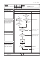
(3)
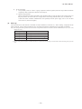
Compressor soft start control
(a) Compressor protection start I
[Control condition] Normally, the compressor operation frequency is raised in this start pattern.
[Control contents] 1) Starts with the compressor’s target frequency at A rps.
However, when the ambient air temperature (Tho-A) is 35°C or higher during cooling/
dehumidifying or the indoor return air temperature (ThI-A) is 25°C or higher during heating, it
starts at C rps.
2) At 30 seconds after the start of compressor, its target frequency changes to B rps and the
compressor is operated for 2 - 4 minutes with its operation frequency fixed at B rps.
Model
71
100
125, 140
Operation mode
Cooling/Dehumidifying
Heating
Cooling/Dehumidifying
Heating
Cooling/Dehumidifying
Heating
A rps
42
62
55
55
45
45
B rps
42
62
55
55
45
45
C rps
40
40
30
30
25
25
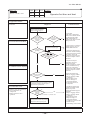
(b) Compressor protection start III
[Control condition] Number of compressor starts is only 1 counted after the power supply breaker ON.
[Control contents] Operates by selecting one of following start patterns according to the operation mode and the
outdoor air temperature (Tho-A).
1) Low frequency operation control during cooling/dehumidifying
[Control condition] Upon establishing the conditions of compressor protection start III, the low frequency
operation control is performed during cooling/dehumidifying.
[Control contents] a) Starts with the compressor’s target frequency at A rps. When the outdoor air temperature
(Tho-A) is 35°C or higher, it starts at C rps.
b) At 30 seconds after the compressor start, the compressor’s target frequency is changed to B
rps and the compressor’s operation frequency is fixed for 10 minutes.
Model
71
100
125, 140
2)
Operation mode
Cooling/Dehumidifying
Cooling/Dehumidifying
Cooling/Dehumidifying
A rps
B rps
C rps
42
55
45
42
55
45
40
30
25
Low frequency operation control during heating
[Control condition] When the conditions of compressor protection start III are established and one of following conditions
a) and b) is satisfied, the low number of revolutions operation control is performed during heating.
a) At 30 minutes or more after turning the power supply breaker on
b) Compressor underneath temperature (Tho-H) is 4°C or higher and the difference from the
outdoor air temperature (Tho-A) becomes 4°C or higher. [model 200, 250 only]
[Control contents] a) Starts the compressor with its target frequency at A rps. However, when the indoor unit
return air temperature (ThI-A) is 25°C or higher, it start at C rps.
b) At 30 seconds after the start of compressor, the compressor’s target frequency is changed to
B rps and the compressor’s operation frequency is fixed for 10 minutes.
Model
71
100
125, 140
Operation mode
Heating
Heating
Heating
-
21 -
A rps
42
55
45
B rps
42
55
45
C rps
40
30
25
'10 • PAC-SM-137
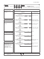
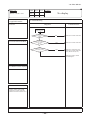
(4)
Outdoor unit fan control
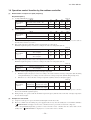
(a) Outdoor unit fan tap and fan motor speed
Model
Mode
71
Cooling/Dehumidifying
Heating
100
Cooling/Dehumidifying
Heating
125, 140
Cooling/Dehumidifying
Heating
Unit: min-1
Fan motor tap
speed speed speed speed speed speed speed
200
400
600
710
810
850
950
200
400
600
710
810
850
950
speed speed speed speed speed speed speed
200
350
600
740
820
870
950
200
350
600
740
820
870
950
speed speed speed speed speed speed speed
200
370
560
640
745
870
910
200
370
560
640
800
870
910
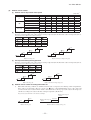
(b) Fan tap control during cooling/heating operation
Fan taps are selected depending on the outdoor unit heat exchanger temperature (Tho-R1, R2) and the outdoor air temperature (Tho-A).
Note (1) It is detected by Tho-R1 or R2, whichever the higher.
zone
Tap 5(6)
Tap 5(6)
Tap 4
Tap 3
zone
zone
zone
zone
zone
Tap 5(6)
Tap 5(6)
Tap 4
Tap 3
zone
Tap 5(6)
Tap 4(6)
Tap 3
Tap 2
zone
Tap 4
Tap 3
Tap 2
Tap 1
Note (1) Value in ( ) are for the model 71.
zone
zone
zone
zone
30
zone
15
zone
46
48
43
zone
37
33
zone
18
20
Outdoor air temp. (˚C)
53
40
30
Outdoor unit heat exchanger temp. (˚C)
(c) Fan tap control during heating operation
Fan taps are selected depending on the outdoor unit heat exchanger temperature (Tho-R1, R2) and the outdoor air temperature (Tho-A).
Note (1) It is detected by Tho-R1 or R2, whichever the lower.
zone
Tap 3
Tap 3
Tap 4
zone
zone
zone
Note (1) Value in (
zone
Tap 3
Tap 4(5)
Tap 5
zone
Tap 4
Tap 5
Tap 6
) are for the model 71.
zone
zone
zone
zone
12
zone
3
15
1
zone
9
-2
Outdoor air temp. (˚C)
3
0
Outdoor unit heat exchanger temp. (˚C)
(d) Outdoor unit fan control at cooling low outdoor air
1)
When all the following conditions are established after the start of compressor, the following control is implemented.
If the outdoor air temperature (Tho-A) is in the zone
in the cooling/dehumidifying mode, it has elapsed 20
seconds from the start of outdoor unit fan and the outdoor unit fan is at the tap 1 speed, the outdoor unit fan speed is
controlled according to the outdoor unit heat exchanger temperature (Tho-R1, R2).
Note (1) It is detected with Tho-R1 or R2, whichever the higher.
Outdoor unit fan speed
+10min-1
Retained
zone
Outdoor unit fan speed
-10min-1
zone
5
10
20
Outdoor air temp. (˚C)
30
Outdoor unit heat exchanger temp. (˚C)
-
22 -
'10 • PAC-SM-137
2)
The outdoor unit heat exchanger temperature is detected always and, when the number of revolutions of the outdoor
fan speed has been increased or decreased, there is no change of fan speed for 20 seconds.
3) Rage of the outdoor unit fan speed under this control is as follows.
a) Lower limit: 130rpm
b) Upper limit: 500rpm
4) As any of the following conditions is established, this control terminates.
a) When the outdoor air temperature is in the zone and the outdoor unit heat exchanger temperature at 30°C or
higher is established for 40 seconds or more continuously.
b) When the outdoor fan speed is 500rpm and the outdoor unit heat exchanger temperature at 30°C or higher is
established for 40 seconds or more continuously.
c) When the outdoor unit heat changer temperature at 45°C or higher is established for 40 seconds or more.
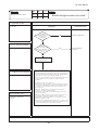
(e) Outdoor unit fan control by the power transistor radiator fin temperature
When all the following conditions are established later than 3 minutes after the start of compressor, the following control
is implemented.
1) Cooling/dehumidifying
a) Outdoor air temperature Tho-A 33°C
b) Compressor’s actual frequency A rps
c) Power transistor radiator fin temperature C °C
2) Heating
a) Outdoor air temperature Tho-A 16°C
b) Compressor’s actual frequency B rps
c) Power transistor radiator fin temperature C °C
3) Control contents
a) Raises the outdoor unit fan tap by 1 tap.
b) When the sampling is for 60 minutes and the value of power transistor radiator fin temperature (Tho-P) is as
follows.
When the power transistor radiator fin temperature (Tho-P) C °C, the outdoor unit fan tap is raised by 1 speed
further.
When C °C > power transistor radiator fin temperature (Tho-P) D °C, present outdoor unit fan tap is
maintained.
When the power transistor radiator fin temperature (Tho-P) D °C, the outdoor unit fan tap is dropped by 1
speed.
4) Ending conditions
When the operation under the condition of item b), above and with the outdoor unit fan tap, which is determined
by the item (b) is detected 2 times consecutively.
• Compressor’s frequency and power transistor radiator fin temperature
Item
Model
71
100
125, 140
(f)
A
B
C
D
60
85
65
70
85
65
80
72
72
75
68
68
Caution at the outdoor unit fan start control
When the outdoor unit fan is running at 400min-1 before operating the compressor, it may operate with the compressor
only, without starting up the outdoor fan This is normal.
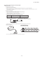
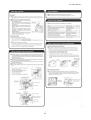
(g) Snow protection fan control
If the dip switch (SW3-2) on the outdoor unit control PCB is turned ON, the outdoor unit fan is operated for 30 seconds
at 4 tap speed once in every 10 minutes depending on the outdoor air temperature (detected with Tho-A) in the stop mode
or anomalous stop mode.
Snow protection fan
control OFF
Snow protection fan
control ON
3
5
Outdoor air temp. (°C)
-
23 -
'10 • PAC-SM-137
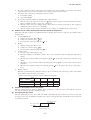
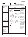
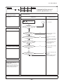
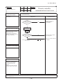
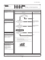
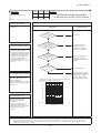
Defrosting
Model 71 ~ 140
-2
Outdoor unit heat exchanger temp.(͠)㨇Tho-R㨉
(a) Defrosting start conditions
LPT invalid
-35
-25
ion
4
e
st o
tur
era
to
s
fro
Defrost operation start
temperature zone
p
tem
t
tar
s
ion
)
rd
da
an
t
(S
)
rat
pe
De
-20 -18
-15
-10
-5
0
56
10
Outdoor air temp. (͠)㨇Tho-A㨉
)
ON
3-1
st o
fro
De
star
(SW
e
mp
t te
n
atio
re
ratu
)
rd
per
da
tan
S
e(
ur
rat
pe
t
tar
tem
Defrost operation start
temperature zone
ns
tio
era
st
op
fro
De
-20 -18
-15
-10
-5
0
56
10
Model 100 ~ 140
Outdoor air temp. (°C)
-8
Note (1) Figures in [ ] are for model 71.
Defrosting conditions B
b)
c)
sta
fro
De
ON
3-1
(SW
Outdoor air temp. (͠)㨇Tho-A㨉
2
a)
per
at
per
LPT detection
2)
re
atu
em
rt t
Suction saturation temp.(͠)㨇SST㨉
If all of the following defrosting conditions A or conditions
-5
-6
B are met, the defrosting operation starts.
1) Defrosting conditions A
-10
a) Cumulative compressor operation time after the
end of defrosting has elapsed 37 [45] minutes,
-15
and the cumulative compressor operation time
after the start of heating operation (remote
-20
controller ON) has elapsed 30 minutes.
b) After 5 minutes from the compressor ON
-25
c) After 5 minutes from the start of outdoor unit fan
-27
d) After satisfying all above conditions, if temperatures
of the outdoor unit heat exchanger temperature
-30
-25
thermistor (Tho-R1, R2) and the outdoor air
temperature thermistor (Tho-A) become lower
than the defrosting start temperature as shown Model 71
-8
by the right figure for 15 seconds continuously,
or the suction gas saturation temperature (SST)
-10
and the outdoor air temperature (Tho-A), which
-15
are obtained from the value detected by the
low pressure sensor (LPT) stay for 3 minutes
-20
within the range below the defrosting operation
start temperature as shown by the right figure.
-24
-25
However, it excludes for 10 minutes after the start
of compressor and the outdoor air temperature is
-30
as shown by the lower figure.
-31
When previous defrosting end condition is
the time out of defrosting operation and it is
in the heating operation after the cumulative
compressor operation time after the end of
defrosting has become 30 minutes.
After 5 minutes from the start of compressor
After 5 minutes from the start of outdoor unit fan
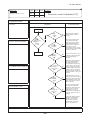
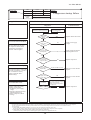
(b) Defrosting end conditions
Suction saturation temp.(͠)㨇SST㨉
(5)
-10
-15
ta
ns
tio
era
-20
-24
-25
-28.6
-30
-25
em
rt t
rd)
da
tan
S
e(
ur
rat
pe
ns
tio
era
p
to
os
fr
De
re
atu
)
ON
m
t te
tar
p
st o
fro
De
per
3-1
(SW
Defrost operation start
temperature zone
-20 -18 -15
-10
-5
0
56
10
When any of the following conditions is satisfied, the
Outdoor air temp. (͠)㨇Tho-A㨉
defrosting end operation starts.
1) When it has elapsed 8 minutes and 20 seconds after the start of defrosting. (After 10 minutes and 20 seconds for model 71)
2) When the outdoor unit heat exchanger temperatures (Tho-R1, R2), whichever the lower, becomes 12°C or higher for
10 seconds continuously.
-
24 -
'10 • PAC-SM-137
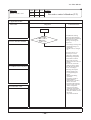
(c) Switching of defrosting control with SW3-1
1)
2)
If SW3-1 on the outdoor unit control PCB is turned to ON, it becomes easier to enter the defrosting operation. Use
this when installing a unit at snowing regions.
Control contents
a) It allows entering the defrosting operation under the defrosting condition A when the cumulative heating
operation time becomes 30 minutes. It is 37 [45] minutes at SW3-1 OFF (Factory default).
b) It allows entering the defrosting operation under the defrosting condition B when the cumulative heating
operation time becomes 25 minutes. It is 30 minutes at SW3-1 OFF (Factory default).
c) It allows the defrosting operation with the outdoor unit heat exchanger temperature (Tho-R) and suction
pressure saturation temperature (SST) being higher than normal.
Note (1) Figures in [ ] are for model 71.
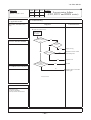
(6)
Protective control/anomalous stop control by compressor’s number of revolutions
(a) Compressor discharge pipe temperature protection
1)
Protective control
As the discharge pipe temperature (detected with Tho-D) exceeds the setting value, the compressor speed (frequency)
is controlled to suppress the rise of discharge pipe temperature.
Reduces compressor
speed at each minute.
Retention
Release
105
110
Discharge pipe temperature (°C)
2)
Anomalous stop control
a)
b)
If the discharge pipe temperature (detected with Tho-D) exceeds the setting value, the compressor stops.
When it is detected 2 times within 60 minutes or after continuous 60 minutes, including the stop of compressor,
E36 is displayed on the remote controller and it enters the anomalous stop mode.
Compressor stop
Compressor operation
85
115
Discharge pipe temperature (°C)
3)
Reset of anomalous stop mode
As it drops to the reset value of 85°C or lower for 45 minutes continuously, it becomes possible to restart from the
remote controller.
(b) Cooling high pressure protection
1)
Protective control
a) When the outdoor air temperature (Tho-A) is 40°C or higher and the outdoor unit heat exchanger temperature (Tho-R)
exceeds the setting value, the compressor speed (frequency) is controlled to suppress the rise of high pressure.
b) Control value A is updated to an optimum value automatically according to the operating conditions.
Reduces compressor
speed at each minute.
Control value A
Reset
A
Outdoor unit heat exchanger temp. (°C)
2)
54~60°C
Anomalous stop control
a) As the outdoor unit heat exchanger temperature (Tho-R) exceeds the setting value, the compressor stops.
b) If it is detected 5 times within 60 minutes or 65°C or higher continues for 60 minutes, including the stop of
compressor, E35 is displayed on the remote controller and it enters the anomalous stop mode.
Compressor stop
Compressor operation
1
5
65
Outdoor unit heat exchanger temp. (°C)
3)
Reset of anomalous stop mode
As it reaches the reset value of 51°C or lower, it becomes possible to restart from the remote controller.
-
25 -
'10 • PAC-SM-137
(c) Heating high pressure protection
1) Protective control
a) As the indoor unit heat exchanger temperature (Th I-R) exceeds the setting value, the compressor speed
(frequency) is controlled to suppress the rise of high pressure.
b) Control value A is updated to an optimum value automatically according to the operating conditions.
Reduces compressor frequency
at every 30 seconds.
Model
Reset
71
100~140
A
Indoor unit heat exchanger temp. (°C)
2)
3)
Existing piping adaptation switch: SW5-1 (SW8-1: model 80)
OFF (Shipping)
ON
Control value A (°C)
52~58
48~54
46~52
Note (1) Adaptation to existing piping is at ON.
Anomalous stop control
Operation control function by the indoor unit controller - See the heating overload protection, page 10.
Adaptation to existing piping, stop control
If the existing piping adaptation switch, SW5-1 (SW8-1: 71 type), is turned ON, the compressor stops to protect
existing piping when the indoor unit heat exchanger temperature (ThI-R) exceeds the setting value.
Compressor stop
Reset
7
4
8
5
Indoor unit heat exchanger temp. (°C)
(d) Anomaly detection control by the high pressure switch (63H1)
If the pressure rises and operates the high pressure switch (opens at 4.15MPa/closes at 3.15MPa), the compressor stops.
Under any of the following conditions, E40 is displayed and it enters the anomalous stop mode.
a) When it occurs 5 times within 60 minutes that pressure rises and the compressor is stopped by 63H1.
b) When 63H1 has been in the open state for 60 minutes continuously, including the stop of compressor.
(e) Low pressure control
1) Protective control
If the value detected by the low pressure sensor (LPT) exceeds the setting value, the compressor speed (frequency)
is controlled to restrain the drop of pressure.
1)
2)
Reduces compressor frequency
at every 30 seconds.
Retention
Reset
0.150
0.189
Low pressure (MPa)
2)
Reduces compressor frequency at each minute.
Indoor unit heat exchanger temp. (°C)
(f)
Anomalous stop control
a) When a value detected by the low pressure sensor (LPT) satisfies any of the following conditions, the
compressor stops to run for its protection.
When the low pressure drops to 0.079MPa or under for 15 seconds continuously.
At 10 minutes after the start of compressor, the suction overheat becomes 30°C and the low pressure
becomes 0.15MPa or under for 60 seconds continuously.
b) E49 is displayed under any of the following conditions and it enters the anomalous stop mode.
When the low pressure drops 3 times within 60 minutes and the compressor stops under any of the above conditions.
When a value detected with the low pressure sensor becomes 0.079MPa or under for 5 minutes, including
the stop of compressor.
c) However, when the control condition a). is established during the compressor protection start III, E49 is
displayed at initial stop and it enters the anomalous stop mode.
Compressor pressure ratio protection control
1) During heating operation, if the indoor unit heat exchanger temperature (ThI-R) and the outdoor unit heat exchanger
temperature (Tho-R) exceed the setting values at 10 minutes after the start of compressor, the compressor speed
(frequency) is controlled to protect the compressor.
2) This control is not performed during the outdoor fan ON and for 10 minutes from the start of outdoor unit fan.
3) This control is not performed during defrosting operation and at 10 minutes after the reset of defrosting operation.
4) When there are 3 indoor unit heat exchanger temperatures (ThI-R), the highest temperature is detected.
65°C
Resert
33°C
0.150
0.425
Low pressure (MPa)
-
26 -
'10 • PAC-SM-137
(g) Over-current protection current safe controls I, II
Detecting the outdoor unit inverter input (primary) current and the output (secondary) current, if the current values exceed
setting values, the compressor speed (frequency) is controlled to protect the inverter.
Reduces frequency
at each minute.
Model
Retention
Reset
B
71
100
125, 11.0 (23.0) 10.0 (22.0) 11.0 (25.0) 10.0 (24.0)
140
71
13.0
12.0
13.0
12.0
Secandary 100 11.5 (Fig.C) 10.5 (Fig.C) 11.5 (Fig.C) 10.5 (Fig.C)
current
side
125, 11.5 (Fig.C) 10.5 (Fig.C) 11.5 (Fig.C) 10.5 (Fig.C)
140
Primary
current
side
A
Current (A)
T
he controlv alue “ A”and the reset v alue v ary depending
on the compressor speed.
Controlor reset v alv e (A)
(F
ig
. C)
4
2
2
Cooling
Heating
Control
Reset
Control
Reset
value A
value B
value A
value B
15.0
14.0
16.0
15.0
13.5 (23.0) 12.5 (22.0) 13.5 (23.0) 12.5 (22.0)
Control av lv e A
Note (1) Value in ( ) are for the single phase models.
0
2
8
1
6
1
Reset valv e B
4
1
2
1
0
4
0
5
60
70
80
09
0
1
0
1
01
2
130
Compressor speed (frequenc y) (rps)
(h) Power transistor temperature protection
1) Protective control
If the power transistor temperature (detected with TIP) exceeds the setting value, the compressor speed (frequency)
is controlled to suppress the rise of power transistor temperature.
Reduces compressor frequency
at each minute.
Retention
Reset
81
85
Power transistor temp. (°C)
(i)
Anomalous power transistor current
Prevents over-current on the inverter. If the current value in the power transistor exceeds the setting value, the
compressor stops.
2) If the current value in the power transistor exceeds the specified value and the compressor stops 4 times within 30
minutes, E42 is displayed on the remote controller and it enters the anomalous stop mode.
(j) Anomalous inverter PCB
If the power transistor detects any anomaly for 15 minutes, including the stop of compressor, E51 is displayed on the
remote controller and it enters the anomalous stop mode.
(k) Anti-frost control by the compressor frequency control
1) If the indoor unit heat exchanger temperature (detected with ThI-R) exceeds the setting value at 4 minutes after the
start of compressor, the compressor speed (frequency) is controlled to initiate the anti-frost control of indoor unit
heat exchanger.
2) When there are 3 indoor unit heat exchanger temperatures (ThI-R), the lowest temperature is detected.
1)
Reset
Reduces compressor frequency
at each minute.
Retention
1.5
3.5
Indoor unit heat exchanger temp. (°C)
3)
Regarding the anti-frost control by the operation stop, refer to the operation control function by the indoor unit
controller and the cooling, dehumidifying frost prevention of page 10.
-
27 -
'10 • PAC-SM-137
(l)
Dewing prevention control
[Control condition] During cooling and dehumidifying operation, if all the following conditions are established, the
compressor speed (frequency) is reduced to prevent dewing and water splash.
Cooling electronic expansion valve aperture (EEVC) is 500 pulses.
Suction overheat is 10°C or higher.
zCompressor speed (frequency) is A rps or higher.
[Control contents] When the suction overheat is 10°C or higher, the compressor speed (frequency) is reduced at each
1 minute.
Compressor speed (frequency) does not rise till the cooling
Model
A rps
expansion valve becomes 460 pulses.
71
42
z This control takes A rps as its lower limit so that compressor
speed is not controlled when it is less than A rps.
100~140
60
(m) Refrigerant quantity shortage protection
Under the compressor protection start III control during cooling and dehumidifying operations, the following control is
performed by detecting the indoor unit heat exchanger temperature (ThI-R) and the indoor unit return air temperature
(ThI-A).
[Control condition] When the state that the indoor unit heat exchanger temperature (ThI-R) does not become lower than
the indoor unit return air temperature (ThI-A) by 4°C or more continues for 1 minute.
[Control contents]
It judges that the flowing of refrigerant in to the indoor unit is insufficient so that the compressor is
stopped and E57 is displayed on the remote controller.
(n) Broken wire detection on temperature thermistor and low pressure sensor
1)
Outdoor unit heat exchanger thermistor, outdoor air thermistor and low pressure sensor
If the following is detected for 5 second continuously within 2 minutes to 2 minutes and 20 seconds after the
compressor ON, the compressor stops. After a delay of 3 minutes, it restarts but, if the same is detected repeatedly 3
times within 40 minutes, the compressor stops with the anomalous stop.
Note (1) During defrosting and for 3 minutes after the end of defrosting, it is not detected.
2)
• Outdoor unit heat exchanger thermistor: -50°C or lower
• Outdoor air temperature thermistor: -45 or lower
• Low pressure sensor: 0V or under or 4.0V or over
Discharge pipe temperature thermistor, suction pipe temperature thermistor
If the following is detected for 5 second continuously within 10 minutes to 10 minutes and 20 seconds after the
compressor ON, the compressor stops. After a delay of 3 minutes, it restarts but, if the same is detected repeatedly 3
times within 40 minutes, the compressor stops with the anomalous stop.
Note (1) During defrosting and for 3 minutes after the end of defrosting, it is not detected.
• Discharge pipe temperature thermistor: -10°C or lower
• Suction pipe temperature thermistor: -50 or lower
(o) Open phase protection (3-phase models only)
When 0V is detected on any of L1, L2 or L3 phase for 5 seconds continuously after the power ON, it judges the state of
open phase on the power supply and activates the anomalous stop (E34) 1 second later.
(p) Fan motor error
1)
If the fan speed of 100rpm or under is detected for 30 second continuously under the outdoor unit fan control (with
the operation command of fan tap at speed or higher), the compressor stops.
2) When the fan motor speed drops to 100rpm or under 5 times within 60 minutes and the compressor stops, it enters
the anomalous stop mode with E48 displayed on the remote controller.
(q) Anomalous stop by the compressor start stop
1)
2)
When it fails to shift to the compressor DC motor’s rotor position defection operation at 5 seconds after establishing
the compressor start condition, the compressor stops temporarily and restarts 3 minutes later.
If it fails to shift to the position detection operation again at second time, it judges the anomalous compressor start
and stops the compressor by the anomalous stop (E59).
-
28 -
'10 • PAC-SM-137
(7)
Silent mode
(a)
(b)
(8)
As “Silent mode start” signal is received from the remote controller, it operates by dropping the outdoor unit fan tap and
the compressor speed (frequency).
For details, refer to items (1) and (4) above.
Test run
(a) It is possible to operate from the outdoor unit using the dip switch on the outdoor unit control PCB.
OFF
Cooling test run
SW3-4
ON
SW3-3
(SW5-4)
ON
Heating test run
(SW5-3)
OFF
Normal and end of test run
Make sure to turn SW3-3 (SW5-3) to OFF after the end of operation.
Note (1) Value in ( ) are for the model 71.
(b) Test run control
1)
2)
3)
Operation is performed at the maximum compressor speed (frequency), which is determined for each model.
Each protective control and error detection control are effective.
If SW3-4 (SW5-4) is switched during test run, the compressor is stoped for once by the stop control and the cooling/
heating operation is switched.
Note (1) Value in ( ) are for the model 71.
4)
Setting and display of remote controller during test run
Item
Contents of remote controller setting/display
Mode
Cooling test run
Setting temperature of cooling is 5°C.
Heating test run
Setting temperature of heating (preparation) is 30°C.
(9)
Pump-down control
Turning ON the pump-down switch SW1 (SW9) for 2 seconds during the operation stop or anomalous stop (excluding the
thermostat OFF), the pump-down operation is performed. (This is invalid when the indoor unit is operating. This is effective
even when the indoor unit is stopped by the anomalous stop or the power supply is turned OFF.)
Note (1) Value in ( ) are for the model 71.
(a) Control contents
1)
2)
3)
4)
Close the operation valve at the liquid side. (It is left open at the gas side.)
Compressor is started with the target speed (frequency) at 71:62, 100:55, 125・140:45 rps in the cooling mode.
Red and green lamps (LED) flash continuously on the outdoor unit control PCB.
Each of protection and error detection controls, excluding the low pressure control, anti-frost control and dewing
prevention control, is effective.
5) Outdoor unit fan is controlled as usual.
6) Electronic expansion valve is fully opened.
(b) Control ending conditions
Stop control is initiated depending on any of the following conditions.
1) Low pressure of 0.087MPa or lower is detected for 5 seconds continuously.
a) Red LED: Light, Green LED: Flashing, Remote controller: Displays stop.
b) It is possible to restart when the low pressure is 0.087MPa or higher.
c) Electronic expansion valve (cooling/heating) is kept fully open.
2) Stop by the error detection control
a) Red LED: Flashing, Green LED: Flashing
b) Restart is prohibited. To return to normal operation, reset the power supply.
c) Electronic expansion valve (cooling/heating) is left fully open.
3) When the cumulative operation time of compressor under the pump-down control becomes 5 minutes.
a) Red LED: OFF, Green LED: Flashing, Remote controller: Stop
b) It is possible to pump-down again.
c) Electronic expansion valve (cooling/heating) is left fully open.
Note (1) After the stop of compressor, close the operation valve at the gas side.
Caution: Since pressing the pump-down switch cancels communications with the indoor unit, the indoor unit and the
remote controller display “Transmission error – E5”. This is normal.
-
29 -
'10 • PAC-SM-137
(j)
Drain pan ON/OFF output control (optional) (Models 100 ∼ 140 only)
1) Drain pan heater ON conditions
When all of following conditions are met, the drain pan heater is turned ON.
・Outdoor air temperature (detected with Tho-A) is 3ºC or lower.
・In the heating mode
・When the compressor is turned ON
2)
Drain pan heater OFF conditions
When either one of following conditions is met, the drain pan heater is turned OFF.
・Outdoor air temperature (detected with Tho-A) is 5ºC or higher.
・When the compressor stop has been detected for 30 minutes continuously
・In the cooling or dehumidifying mode
Drain pan heater OFF
Drain pan heater ON
3
5
Outdoor air temperature (ºC) [Tho-A]
-
30 -
'10 • PAC-SM-137
2. MAINTENANCE DATA
2.1 Diagnosing of microcomputer circuit
(1)
Selfdiagnosis function
(a) Check Indicator Table
(i)
Whether a failure exists or not on the indoor unit and outdoor unit can be know by the contents of remote controller error code,
indoor/outdoor unit green LED (power pilot lamp and microcomputer normality pilot lamp) or red LED (check pilot lamp).
Indoor unit
Remote controller
Error code
Red LED
Indoor control PCB
Green
LED (1)
Red LED
Stays OFF
Keeps
flashing
No-indication Stays OFF Stays OFF Stays OFF
or
INSPECT I/U
WAIT
Outdoor control PCB
Green
LED (1)
Red LED
Stays OFF
Keeps
flashing
2 times
flash
Stays OFF
Keeps
flashing
*
3 times
flash
Keeps
flashing
Stays OFF
Stays OFF
Keeps
flashing
2 times
flash
Keeps
flashing
Location of
trouble
—
Description of trouble
• Normal operation
Indoor unit power
• Power OFF, broken wire/blown fuse, broken transformer wire
supply
Remote controller • Poor connection, breakage of remote controller wire * For wire breaking at power ON, the
wires
LED is OFF.
Reference
page
—
—
Repair
62
Repair
Replacement of
remote controller
Remote controller • Defective remote controller PCB
Indoor-outdoor
units connection
wire
Repair method
• Poor connection, breakage of indoor-outdoor units connection wire
Repair
63
64 ∼ 68
Remote controller • Improper setting of master and slave by remote controller
Stays OFF
*
Keeps
flashing
Stays OFF
Keeps
flashing
2 times
flash
Keeps
flashing
2 times
flash
Keeps
flashing
2 times
flash
Keeps
flashing
Stays OFF
Keeps
flashing
Remote controller
wires (Noise)
• Poor connection of remote controller signal wire (White)
* For wire breaking at power ON, the LED is OFF
• Intrusion of noise in remote controller wire
Remote controller
indoor control PCB
*• Defective remote controller or indoor control PCB (defective communication circuit)?
Indoor-outdoor
units connection
wire
(Noise)
Outdoor control
PCB
Outdoor control
PCB
• Poor connection of wire between indoor-outdoor units during operation
(disconnection, loose connection)
• Anomalous communication between indoor-outdoor units by noise, etc.
• CPU-runaway on outdoor control PCB
*• Occurrence of defective outdoor control PCB on the way of power supply (defective communication circuit)?
• Defective outdoor control PCB on the way of power supply
Repair
Replacement of
remote controller or
PCB
70
Repair
Power reset or
Repair
Replacement of
PCB
71
2 times
flash
Keeps
flashing
1 time flash
Keeps
flashing
Stays OFF
Keeps
flashing
1 time flash
Keeps
flashing
Stays OFF
Keeps
flashing
1 time flash
Keeps
flashing
Stays OFF
Keeps
flashing
1 time flash
Keeps
flashing
Stays OFF
Keeps
flashing
Stays OFF
Keeps
flashing
Stays OFF
Keeps
flashing
3 times
flash
Keeps
flashing
Stays OFF
Keeps
flashing
Stays OFF
Keeps
flashing
Stays OFF
Keeps
flashing
1 time flash
Keeps
flashing
Stays OFF
Keeps
flashing
Indoor control PCB • Improper operation mode setting
Repair
79
Keeps
flashing
Remote controller
temperature therm- • Broken wire of remote controller temperature thermistor
istor
Repair
80
Stays OFF Stays OFF
Fuse
Keeps
flashing
Indoor heat
• Defective indoor heat exchanger temperature thermistor (defective element, broexchanger tempera- ken wire, short-circuit)
ture thermistor • Poor contact of temperature thermistor connector
Replacement, repair
of temperature
thermistor
Replacement of
Indoor control PCB *• Defective indoor control PCB (Defective temperature thermistor input
PCB
circuit)?
Indoor return air • Defective indoor return air temperature thermistor (defective element, broken wire, Replacement, repair
temperature therm- short-circuit)
of temperature
istor
• Poor contact of temperature thermistor connector
thermistor
Replacement of
Indoor control PCB *• Defective indoor control PCB (Defective temperature thermistor input
PCB
circuit)?
Installation or oper• Heating over-load (Anomalously high indoor heat exchanger temperature)
Repair
ating condition
Indoor heat
Replacement of
exchanger tempera- • Defective indoor heat exchanger temperature thermistor (short-circuit)
temperature thermture thermistor
istor
Replacement of
Indoor control PCB *• Defective indoor control PCB (Defective temperature thermistor input circuit)?
PCB
Replacement, repair
Drain trouble
• Defective drain pump (DM), broken drain pump wire, disconnected connector
of DM
Float switch
Indoor control PCB
Option
Stays OFF
Keeps
flashing
Stays OFF
Replacement
• Blown fuse
• Anomalous float switch operation (malfunction)
72
73
74
Repair
*• Defective indoor control PCB (Defective float switch input circuit)
*• Defective indoor control PCB (Defective DM drive output circuit)?
• Defective optional parts (At optional anomalous input setting)
Number of con- • When multi-unit control by remote controller is performed, the number of
nected indoor units units is over
Indoor unit No. set•No master is assigned to slaves.
ting
Replacement of
PCB
75
Repair
Repair
76
Repair
77
Rcmote controller wires •Anomalous remote controller wire connection, broken wire between master and slave units
Fan motor
• Defective fan motor
Indoor control PCB • Defective indoor control PCB
Replacement, repair
(In case of FDTC, FDT, SRK)
Replacement
78
Note (1) Normal indicator lamp (Indoor, outdoor units: Green) extinguishes (or lights continuously) only when CPU is anomalous. It keeps
flashing in any trouble other than anomalous CPU.
PDUNLQWKH'HVFULSWLRQRIWURXEOHPHDQVWKDWLQRUGLQDU\GLDJQRVLVLWFDQQRWLGHQWLI\WKHFDXVHGH¿QLWHO\DQGLIWKHWURXEOHLVUHSDLUHGE\UHSODFLQJ
the part, it is judged consequently that the replaced part was defective.
-
31 -
'10 • PAC-SM-137
(ii) Outdoor unit
Remote controller
Indoor control PCB
Outdoor control PCB Outdoor inventer PCB
Error code Red LED Red LED
Green
LED (1)
Red LED
Green
LED (1)
Stays OFF
Keeps
flashing
1 time flash
Keeps
flashing
Yellow
LED
Location of trouble
Power supply wires
Outdoor control PCB
Description of trouble
• Outdoor unit power supply L3-phase interruption, defective noise filter
(3-phase model only)
*• Defective outdoor control PCB (Defective power supply input circuit)?
(3-phase model only)
Installation or operating
• Higher outdoor heat exchanger temperature
condition
Stays OFF
Stays OFF
Keeps
flashing
Keeps
flashing
1 time flash
1 time flash
Keeps
flashing
Keeps
flashing
Keeps
flashing
Keeps
flashing
Outdoor heat exchanger
• Defective outdoor heat exchanger temperature thermistor
temperature thermistor
*• Defective outdoor control PCB (Defective temperature thermistor input
Outdoor control PCB
circuit)?
Installation or operating • Higher discharge temperature
condition
Discharge pipe
• Defective discharge pipe temperature thermistor
temperature thermistor
*• Defective outdoor control PCB (Defective temperature thermistor input
Outdoor control PCB
circuit)?
Outdoor heat exchanger • Defective outdoor heat exchanger temperature thermistor, broken wire or poor
temperature thermistor connector connection
*• Defective outdoor control PCB (Defective temperature thermistor input
Outdoor control PCB
circuit)?
Outdoor air temperature • Defective Outdoor air temperature thermistor, broken wire or poor connector
thermistor
connection
*• Defective outdoor control PCB (Defective temperature thermistor input
Outdoor control PCB
circuit)?
Discharge pipe
• Defective discharge pipe temperature thermistor, broken wire or poor
temperature thermistor connector connection
*• Defective outdoor control PCB (Defective temperature thermistor input
Outdoor control PCB
circuit)?
Installation or operating
• Rising high pressure (Operation of 63H1) • Service valve closing operation
condition
Keeps
flashing
1 time flash
Keeps
flashing
1 time flash
Keeps
flashing
1 time flash
Keeps
flashing
1 time flash
Stays OFF
Keeps
flashing
1 time flash
Keeps
flashing
2 times flash
or
6 times flash
Inverter PCB or radiator
• Power transistor overheat (Single phase modelonly)
fin
Stays OFF
Keeps
flashing
1 time flash
Keeps
flashing
1 time flash
or
5 times flash
Outdoor control PCB
• Current cut (Anomalous compressor over-current)
compressor
Installation or operating
• Service valve closing operation
condition
Keeps
flashing
1 time flash
Keeps
flashing
Keeps
flashing
Stays OFF
Keeps
flashing
1 time flash
Keeps
flashing
7 times flash
Stays OFF
Keeps
flashing
1 time flash
Keeps
flashing
Stays OFF
Stays OFF
Stays OFF
Stays OFF
Keeps
flashing
Stays OFF
Stays OFF
Keeps
flashing
1 time flash
Keeps
flashing
Keeps
flashing
Keeps
flashing
Keeps
flashing
Outdoor control PCB
Keeps
flashing
1 time flash
Keeps
flashing
Stays OFF
Keeps
flashing
1 time flash
Keeps
flashing
Stays OFF
Keeps
flashing
1 time flash
Keeps
flashing
Keeps
flashing
1 time flash
Keeps
flashing
5 times
flash
Stays OFF
Stays OFF
Repair
Replacement of
temperature thermistor
82
Replacement of PCB
Repair
Replacement, repair of
temperature thermistor
83
Replacement of PCB
Replacement, repair of
temperature thermistor
84
Replacement of PCB
Replacement, repair of
temperature thermistor
85
Replacement of PCB
Replacement, repair of
temperature thermistor
86
Replacement of PCB
Repair
87
Replacement of PCB
Replacement of PCB
or Repair
88
Replacement of PCB
89 •90
Repair
Inverter PCB
• Anomalous inverter PCB communication
Replacement of PCB
Inverter PCB
activefilter
• Defective outdoor inverter PCB (Model FDC 71)
Defective active filter of control.
Replacement
• Anomalous outdoor fan motor
Replacement, repair
*• Defective outdoor control PCB (Defective motor input circuit)?
Replacement of PCB
91
92
93
Outdoor control PCB
Keeps
flashing
2 times flash
or
6 times flash
Installation or operating
• Low pressure error • Service valve closing operation
condition
• Anomalous low pressure, broken wire of low pressure sensor or poor
Low pressure sensor
connector connection
Inverter PCB
*• Defective outdoor control PCB (Defective sensor input circuit)?
• Anomalous inverter PCB
Repair
Replacement, repair of
sensor
Replacement of control
PCB
Replacement of PCB
Suction pipe
• Defective suction pipe temperature thermistor, broken wire or poor connector Replacement, repair of
temperature thermistor connection
temperature thermistor
Replacement of control
Outdoor control PCB *• Defective outdoor PCB (Defective thermistor input circuit)?
PCB
Keeps
flashing
Keeps
flashing
Keeps
flashing
81
Replacement of PCB
Service valve opening
check
Outdoor fan motor
Reference
page
Repair
• Anomalous outdoor control PCB communication
Outdoor control PCB
Outdoor control PCB
Stays OFF
*• Defective outdoor control PCB (Defective 63H input circuit)?
Repair method
Stays OFF or
4 times
flash
Low pressure sensor
• Defective low pressure sensor
Replacement of sensor
Outdoor control PCB
• Defective outdoor control PCB (Defective sensor input circuit)?
Replacement of control
PCB
94,95
96
97
98
Operation status
• Shortage in refrigerant quantity
Repair
• Service valve closing operation
Service valve opening
check
99
Installation status
Compressor inverter
PCB
• Anomalous compressor startup
Replacement
100
Note (1) * mark in the Description of trouble means that, in ordinary diagnosis, it cannot identify the cause definitely, and, if the trouble is repaired by replacing the part, it
is judged consequently that the replaced part was defective.
(iii) Optional controller in-use
Indoor unit control PCB
Outdoor unit control PCB
Red LED
Red LED
Green LED
Red LED
Keeps flashing
Stays OFF
Keeps flashing
Stays OFF
Description of trouble
Error code
Repair method
Green LED
Keeps flashing • Communication error (Defective communication circuit on the main unit of SC-SL2N-E or SC-SL3N-E) ete.
-
32 -
Replacement
'10 • PAC-SM-137
(iv) Display sequence of error codes or inspection indicator lamps
N Occurrence of one kind of error
Displays are shown respectively according to errors.
N Occurrence of plural kinds of error
Section
Error code on remote
controller
Red LED on indoor
control PCB
Red LED on outdoor
control PCB
Category of display
• Displays the error of higher priority (When plural errors are persisting)
• Displays the present errors. (When a new error has occurred after the former error was reset.)
N Error detecting timing
Section
Error description
Drain trouble (Float switch
activated)
Communication error at
initial operation
Error code
“
WAIT
Remote controller
communication circuit error
Communication error during
operation
Indoor Excessive number of
connected indoor units by
controlling with one remote
controller
Error detecting timing
Whenever float switch is activated after 30 second had past since
power ON.
No communication between indoor and outdoor units is
”
established at initial operation.
Communication between indoor unit and remote controller is
interrupted for mote than 2 minutes continuously after initial
communication was established.
Communication between indoor and outdoor units is interrupted
for mote than 2 minutes continuously after initial communication
was established.
Whenever excessively connected indoor units is detected after
power ON.
-50 (-45)°C or lower is detected for 5 (15) seconds continuously
within 60 minutes after initial detection of this anomalous
temperature.
-50 (-28)°C or lower is detected for 5 (15) seconds continuously
within 60 minutes after initial detection of this anomalous
temperature.
Or 70°C or higher is detected for 5 seconds continuously.
-45°C or lower is detected for 5 seconds continuously 3 times
within 40 minutes after initial detection of this anomalous
temperature.
Or -45°C or higher is detected for 5 seconds continuously within
20 seconds after compressor ON.
-50°C or lower is detected for 5 seconds continuously 3 times
within 40 minutes after initial detection of this anomalous
temperature.
Or -50°C or lower is detected for 5 seconds continuously within
20 seconds after compressor ON.
-10°C or lower is detected for 5 seconds continuously 3 times
within 40 minutes after initial detection of this anomalous
temperature.
-50°C or lower is detected for 5 seconds continuously 3 times
within 40 minutes after initial detection of this anomalous
temperature.
0V or lower or 3.49V or higher is detected for 5 seconds
continuously 3 times within 40 minutes after initial detection of
this anomalous pressure.
-50°C or lower is detected for 5 seconds continuously 3 times
within 40 minutes after initial detection of this anomalous
temperature.
Return air temperature
thermistor anomaly
Indoor heat exchanger
temperature thermistor
anomaly
Outdoor air temperature
thermistor anomaly
Outdoor heat exchanger
temperature thermistor
anomaly
Outdoor Discharge pipe temperature
thermistor anomaly
Suction pipe temperature
thermistor anomaly
Low pressure sensor anomaly
Underneath temperature
thermistor anomaly
Note (1) Value in ( ) are for the models SRK50, 60.
-
33 -
'10 • PAC-SM-137
N Error log and reset
Error indicator
Memorized error log
Remote controller display
• Higher priority error is memorized.
Red LED on indoor control PCB
• Not memorized.
Red LED on outdoor control PCB
• Memorizes a mode of higher priority.
Reset
• Stop the unit by pressing the ON/OFF
switch of remote controller.
• If the unit has recovered from anomaly, it
can be operated.
N Resetting the error log
• Resetting the memorized error log in the remote controller
Holding down “CHECK” button, press “TIMER” button to reset the error log memorized in the remote controller.
• Resetting the memorized error log
The remote controller transmits error log erase command to the indoor unit when “VENTI” button is pressed while
holding down “CHECK” button.
Receiving the command, the indoor unit erase the log and answer the status of no error.
(2)
Troubleshooting procedure
When any trouble has occurred, inspect as follows. Details of respective inspection method will be described on later pages.
Trouble
(3)
Confirmation
of power
supply
(Indoor/
outdoor unit)
Confirmation of
remote controller and
LEDs on the PCB
of indoor unit and
outdoor unit (Indoor/
outdoor unit, remote
controller)
Check of the anomalous
operation data on the
remote controller
Inspection
of the unit/
controller
Replacement/
repair of
faulty part,
test run,
adjustment
Troubleshooting at the indoor unit
:LWKWKHWURXEOHVKRRWLQJ¿QGRXWDQ\GHIHFWLYHSDUWE\FKHFNLQJWKHYROWDJH$&'&UHVLVWDQFHHWFDWUHVSHFWLYHFRQQHFWRUV
at around the indoor PCB, according to the inspection display or operation status of unit (the compressor does not run, fan does
not run, the 4-way valve does not switch, etc.), and replace or repair in the unit of following part.
(a) Replacement part related to indoor PCB’s
Control PCB, power supply PCB, temperature thermistor (return air, indoor heat exchanger), remote controller switch,
limit switch, transformer and fuse
Note (1) With regard to parts of high voltage circuits and refrigeration cycle, judge it according to ordinary inspection methods.
(b) Instruction of how to replace indoor control PCB
SAFETY PRECAUTIONS
٨
٨
٨
Read the "SAFETY PRECAUTIONS" carefully first of all and then strictly follow it during the replacement in order to protect yourself.
The precautionary items mentioned below are distinguished into two levels, WARNING and CAUTION.
Both mentions the important items to protect your health and safety so strictly follow them by any means.
WARNING Wrong installation would cause serious consequences such as injuries or death.
CAUTION Wrong installation might cause serious consequences depending on circumstances.
After completing the replacement, do commissioning to confirm there are no anomaly.
ޓޓޓޓޓޓޓޓޓޓWARNING
٨
٨
٨
٨
٨
Replacement should be performed by the specialist.
If you replace the PCB by yourself, it may lead to serious trouble such as electric shock or fire.
Replace the PCB correctly according to these instructions.
Improper replacement may cause electric shock or fire.
Shut off the power before electrical wiring work.
Replacement during the applying the current would cause the electric shock, unit failure or improper running.
It would cause the damage of connected equipment such as fan motor,etc.
Fasten the wiring to the terminal securely, and hold the cable securely so as not to apply unexpected stress on the terminal.
Loose connections or hold could result in abnormal heat generation or fire.
Check the connection of wiring to PCB correctly before turning on the power, after replacement.
Defectiveness of replacement may cause electric shock or fire.
ޓޓޓޓޓޓޓޓޓCAUTION
٨
٨
٨
In connecting connector onto the PCB, connect not to deform the PCB. It may cause breakage or malfunction.
Insert connecter securely, and hook stopper. It may cause fire or improper running.
Bundle the cables together so as not to be pinched or be tensioned. It may cause malfunction or electric shock for disconnection or deformation.
-
34 -
'10 • PAC-SM-137
UModel: FDT, FDTC series
PSB012D931F C
• Control PCB
Replace and set up the PCB according to this instruction.
ԘSet to an appropriate address and function using switch on PCB.
ޓSelect the same setting with the removed PCB.
item
switch
Content of control
Address
SW2
Plural indoor units control by 1 remote controller
Master /Slave
setting
Test run
SW5-1
SW5-2
SW7-1
Master
Slave1
Slave2
Slave3
䋭
䋭
䋭
䇳
䇳
䋭
䇳
䇳
Normal
Operation check/drain motor test run
䋭
䇳
䇳㪑㪦㪥䇭䋭㪑㪦㪝㪝
ԙSet to an appropriate capacity using the model selector switch(SW6).
Select the same capacity with the PCB removed from the unit.
ޓ
SW6
-1 -2 -3 -4
SW6
-1 -2 -3
ޚ
ޚ
㧙 㧙
100V ޚ ޚ㧙
40V
ޚ
ޚ
㧙
㧙
50V
125V 㧙 㧙 ޚ
ޚ
ޚ
ޚ
㧙
60V
140V ޚ㧙 ޚ
ޚ
ޚ
㧙 㧙
71V
-4
SW6
ON
ޚ
ޚ
ޚ
1 2 3 4
Example setting fro 50V
ԚReplace the PCB
1. Fix the PCB so as not to pitch the cords.
2. Connect connectors to the PCB. Connect a cable connector with the PCB connector of the same color.
3.Do not pass CPU surrounding about wirings.
ԛControl PCB
Parts mounting are different by the kind of PCB.
㪚㪥㪡㩿㪮㪿㫀㫋㪼䋩
㪣㫆㫌㫍㪼㫉㩷㫄㫆㫋㫆㫉
㪚㪥㪱㩿㪮㪿㫀㫋㪼䋩
㪟㪘
㪚㪥㪫䋨㪙㫃㫌㪼䋩
㪜㫏㫋㪼㫉㫅㪸㫃㩷㫊㫎㫀㫋㪺㪿
㪚㪥㪭䋨㪩㪼㪻䋩
㪘㫌㫋㫆㩷㫃㫀㪽㫋
㪪㪮㪉㩷㩿㪙㫃㫌㪼㪀
㪘㪻㪻㫉㪼㫊㫊㩷㫊㪼㫋㫋㫀㫅㪾
㪚㪥㪮㪋㩿㪙㫃㫌㪼䋩
㪧㫆㫎㪼㫉㩷㪧㪚㪙
㪪㪮㪌
㪤㪸㫊㫋㪼㫉㪆㪪㫃㪸㫍㪼
㫊㪼㫋㫋㫀㫅㪾
㪚㪥㪮㪊㩿㪩㪼㪻䋩
㪧㫆㫎㪼㫉㩷㪧㪚㪙
㪚㪥㪜㩿㪮㪿㫀㫋㪼䋩
㪩㪘㪤㩷㪺㪿㪼㪺㫂㪼㫉
㪚㪥㪞䋨㪙㫃㫌㪼䋩
㪪㪮㪍
㪚㪸㫇㪸㪺㫀㫋㫐㩷㫊㪼㫋㫋㫀㫅㪾
㪧㪸㫉㫋㩷㫅㫌㫄㪹㪼㫉
-
35 -
㪚㪥㪙㩿㪮㪿㫀㫋㪼䋩
㪩㪼㫄㫆㫋㪼
㪺㫆㫅㫋㫉㫆㫃㫃㪼㫉
㪚㪥㪠㩿㪙㫃㫌㪼䋩
㪝㫃㫆㪸㫋㩷㪪㪮
㪚㪥㪚㩿㪩㪼㪻䋩
㪟㫌㫄㫀㪻㫀㫋㫐
㫊㪼㫅㫊㫆㫉
㪚㪥㪟㩿㪙㫃㪸㪺㫂䋩
㪫㪿㪼㫉㫄㫀㫊㫋㫆㫉
㩿㪩㪼㫋㫌㫉㫅㩷㪸㫀㫉㪀
㪚㪥㪭㪉㩿㪙㫃㪸㪺㫂㪀
㪘㫌㫋㫆㩷㫃㫀㪽㫋
㪪㪮㪎
㪝㫌㫅㪺㫋㫀㫆㫅㩷㫊㪼㫋㫋㫀㫅㪾
㪚㪥㪥㩿㪰㪼㫃㫃㫆㫎䋩
㪫㪿㪼㫉㫄㫀㫊㫋㫆㫉
㩿㪟㪼㪸㫋㩷㪼㫏㪺㪿㪸㫅㪾㪼㫉㪀
'10 • PAC-SM-137
• Power PCB
PSB012D953A
This PCB is a general PCB. Replace the PCB according to this instruction.
ԘReplace the PCB
(refer to right dwg.)
1. Unscrew terminal of the wiring(yellow/green) soldered to PCB from the box.
2. Cut the band that binds the wiring (red and blue) from connector CNW1 and CNW2, and the wiring (yellow/green) from PCB (T2/T3) . (Note 1)
㵘(However, do not cut the band that binds only the red and blue wirings.)
3. Replace the PCB only after all the wirings connected to the connector are removed.
4. Fix the board such that it will not pinch any of the wires.
5. Reconnect the wirings to the PCB. Wiring connector color should match with the color of connector of the PCB. (Note 2)
6. Let the wiring (red and blue) pass beneath the (yellow/green) wiring and bind together with band.
7. Screw back the terminal of wiring (yellow/green) from PCB(T1䋬T2/T3), that was removed in 1.
In that case, do not place the crimping part of the wiring under the PCB.
㵘 1): It might not be applicable on some models.
(Note
㵘 2): After replacing PCB, connection between capacitor assy and connector CNP is no longer needed.
(Note
ԙPower PCB
Parts mounting are different by the kind of PCB.
㪚㪥㪤㩿㪮㪿㫀㫋㪼䋩
㪝㪸㫅㩷㫄㫆㫋㫆㫉
㪚㪥㪮㪇䋨㪮㪿㫀㫋㪼䋩
㪫㪼㫉㫄㫀㫅㪸㫃㩷㪹㫃㫆㪺㫂
䌔䋱㩿㪰㪼㫃㫃㫆㫎㪆㪞㫉㪼㪼㫅䋩
㪜㪸㫉㫋㪿
㪚㪥㪮㪈㩿㪙㫃㫌㪼䋩
㪚㫆㫅㫋㫉㫆㫃㩷㪧㪚㪙
㪚㪥㪮㪉㩿㪩㪼㪻䋩
㪚㫆㫅㫋㫉㫆㫃㩷㪧㪚㪙
㪫㪉㩿㪰㪼㫃㫃㫆㫎㪆㪞㫉㪼㪼㫅䋩
㪜㪸㫉㫋㪿
㪫㪊㩿㪰㪼㫃㫃㫆㫎㪆㪞㫉㪼㪼㫅䋩
㪜㪸㫉㫋㪿
㩿㪥㫆㫋㪼㩷㪉㪀㩷㪚㪥㪧㩿㪮㪿㫀㫋㪼㪀
㪚㪸㫇㪸㪺㫀㫋㫆㫉㩷㪸㫊㫊㫐
㪧㪸㫉㫋㩷㫅㫌㫄㪹㪼㫉
-
36 -
㪚㪥㪩䋨㪮㪿㫀㫋㪼䋩
㪛㫉㪸㫀㫅㩷㫄㫆㫋㫆㫉
'10 • PAC-SM-137
-
37 -
'10 • PAC-SM-137
UModel: FDUM, FDU, FDEN series
PSB012D933D D
ԘSet to an appropriate address and function using switch on PCB.
There is a unit having plural applicable PCB depending on a model.
Set the function setting corresponding the spare PCB and the applicable model.
item
switch
Content of control
Address
SW2
Plural indoor units control by 1 remote controller
Master /Slave
setting
Master
Slave1
Slave2
Slave3
䋭
䋭
䋭
䇳
䇳
䋭
䇳
䇳
SW5-1
SW5-2
Test run
䋭
SW7-1
䇳
Normal
Operation check/drain motor test run
ޚ10ޓ㧙1((
ԙSet to an appropriate capacity using the model selector switch(SW6).
Select the same capacity with the PCB removed from the unit.
ޓ
SW6
40V
50V
60V
71V
-1
-2
-3
-4
ޚ
ޚ
㧙
㧙
ޚ
㧙
ޚ
㧙
ޚ
ޚ
ޚ
㧙
ޚ
㧙
㧙
ޚ
SW6
100V
125V
140V
-1
-2
-3
-4
ޚ
ޚ
㧙
ޚ
㧙
㧙
ޚ
ޚ
ޚ
㧙
ޚ
ޚ
SW6
ON
1 2 3 4
Example setting for 50V
ԚReplace the PCB
1. Fix the PCB so as not to pitch the cords.
2. Connect connectors to the PCB. Connect a cable connector with the PCB connector of the same color.
3.Do not pass CPU surrounding about wirings.
ԛControl PCB
Parts mounting are different by the kind of PCB.
㪚㪥㪮㪇㩿㪩㪼㪻䋩
㪧㫆㫎㪼㫉㩷㫊㫆㫌㫉㪺㪼
㪧㪸㫉㫋㩷㫅㫌㫄㪹㪼㫉
㪪㪮㪉㩷㩿㪙㫃㫌㪼㪀
㪘㪻㪻㫉㪼㫊㫊㩷㫊㪼㫋㫋㫀㫅㪾
㪚㪥㪮㪉㩿㪙㫃㪸㪺㫂䋩
㪪㪼㪺㫆㫅㪻㪸㫉㫐
㫋㫉㪸㫅㫊㪽㫆㫉㫄㪼㫉
㪚㪥㪮㪈䋨㪮㪿㫀㫋㪼䋩
㪧㫉㫀㫄㪸㫉㫐㩷㫋㫉㪸㫅㫊㪽㫆㫉㫄㪼㫉
㪪㪮㪌㩷㪤㪸㫊㫋㪼㫉㪆㪪㫃㪸㫍㪼
㫊㪼㫋㫋㫀㫅㪾
㪚㪥㪙㩿㪮㪿㫀㫋㪼䋩
㪩㪼㫄㫆㫋㪼
㪺㫆㫅㫋㫉㫆㫃㫃㪼㫉
㪚㪥㪤㪊䋨㪮㪿㫀㫋㪼䋩
㪝㪸㫅㩷㫄㫆㫋㫆㫉
㪚㪥㪞䋨㪙㫃㫌㪼䋩
㪚㪥㪡㪉㩿㪙㫃㫌㪼䋩
㪣㫆㫌㫍㪼㫉㩷㫄㫆㫋㫆㫉
㪪㪮㪎
㪚㪥㪩㩿㪮㪿㫀㫋㪼䋩
㪛㫉㪸㫀㫅㩷㫇㫌㫄㫇
-
38 -
㪚㪥㪱㩿㪮㪿㫀㫋㪼㪀
㪟㪘
㪚㪥㪟㩿㪙㫃㪸㪺㫂䋩
㪫㪿㪼㫉㫄㫀㫊㫋㫆㫉
㩿㪩㪼㫋㫌㫉㫅㩷㪸㫀㫉㪀
㪚㪥㪥㩿㪰㪼㫃㫃㫆㫎䋩
㪫㪿㪼㫉㫄㫀㫊㫋㫆㫉
㩿㪟㪼㪸㫋
㪼㫏㪺㪿㪸㫅㪾㪼㫉㪀
㪚㪥㪭㩿㪙㫃㪸㪺㫂䋩
㪘㫌㫋㫆㩷㫃㫀㪽㫋
㪚㪥㪪㩿㪙㫃㫌㪼䋩
㪣㫆㫌㫍㪼㫉㩷㪪㪮
㪚㪥㪠㩿㪙㫃㫌㪼䋩
㪝㫃㫆㪸㫋㩷㪪㪮
㪚㪥㪫㩿㪙㫃㫌㪼䋩
㪦㫇㫋㫀㫆㫅
㪚㪥㪨㩿㪮㪿㫀㫋㪼㪀
㪚㪥㪡㩿㪮㪿㫀㫋㪼㪀
㪣㫆㫍㪼㫉㩷㫄㫆㫋㫆㫉
㪧㫌㫃㫊㪼
㪚㪥㪦㩿㪩㪼㪻䋩
㪟㪼㪸㫋㪼㫉
㪚㪥㪜䋨㪮㪿㫀㫋㪼䋩
㪩㪘㪤㩷㪺㪿㪼㪺㫂㪼㫉
'10 • PAC-SM-137
٨DIP switch setting list
Switches
SW2
SW5-1
SW5-2
SW6-1
SW6-2
SW6-3
SW6-4
SW7-1
SW7-2
SW7-3
SW7-4
JSL1
Description
Default setting
Address No. setting at plural indoor units control by 1 R/C
Master/Slave setting
0-F
0
OFF
OFF
Master*/Slave
Model selection
See table 2
As per model
Normal*/Test run
Test run, Drain motor
Reserved
Powerful mode
Reserved
Superlink terminal spare
OFF
OFF
ON
OFF
With
Valid*/Invalid(FDU only)
Normal*/switch to spare
keep OFF
Valid
Table 1: Indoor unit model selection with SW6-1-SW6-4
SW6-1
SW6-2
SW6-3
SW6-4
50V
1
0
1
0
60V
1
1
1
0
71V
1
0
0
1
100V
1
1
0
1
0: OFF 1:ON
125V
140V
0
1
0
0
1
1
1
1
Table 2: Indoor unit Master/Slave setting with SW5-1,SW5-2
Master
Slave1
Slave2
Slave3
0: OFF 1:ON
SW5-1 SW5-2
0
0
0
1
1
0
1
1
-
39 -
See table 1
Normal
* Default setting
40V
1
1
0
0
Remarks
keep OFF
'10 • PAC-SM-137
(4)
Troubleshooting at the outdoor unit
:KHQWURXEOHVKRRWLQJWKHRXWGRRUXQLW¿UVWO\DVVHVVWKHRYHUYLHZRIPDOIXQFWLRQDQGWU\WRSUHVXPHWKHFDXVHDQGWKHIDXOW\
SDUWE\FKHFNLQJWKHHUURUFRUGGLVSDO\HGRQWKHUHPRWHFRQWUROOHUDQGÀDVKLQJSDWWHUQRILQGLFDWRUODPSV5HG/('DQG*UHHQ
LED), and then proceed further inspection and remedy it.
6HOIGLDJQRVLVV\VWHPE\PLFURFRPSXWRURQLQGRRUDQGRXWGRRU3&%FDQDVVLVWWR¿QGWKHFDXVHRIPDOIXQFWLRQVPRRWKO\E\
making a diagnosis of not only the anomaly of microcomutor, but also the anomaly in power supply system, installation space,
overload resulting from improper charging amount of refrigerant and etc.
8QOHVVWKHSRZHULVUHVHWWKHHUURUORJLVVDYHGLQPHPRU\DQGWKHLQVSHFWLRQLQGLFDWRUODPSVRQRXWGRRU3&%NHHSÀDVKLQJ
after automatical recovering from malfunction.
After automatical recovering from malfunction, if any another error mode which has a higher priority than the previous error
saved in memory occurs, it is overwritten in memory and is displayed.
[Reset of power supply]
Be sure to avoid electrical shock, when replacing or checking the outdoor control PCB, because some voltage is still retained in
the electrolytic capacitor on the PCB even after shutting down tne power supply to the outdoor unit.
Be sure to start repairing work, after confirming that the Green LED on the PCB has been extiguished for more than 10
VHFRQGVDIWHUPRUHWKDQPLQXWHVKDGEHHQSDVVHGVLQFHSRZHUVKXWGRZQDQGUHFRQ¿UPLQJWKDWYROWDJHKDVEHHQGLVFKDUJHG
VXI¿FLHQWO\ E\ PHDVXULQJ WKH YROWDJH '& EHWZHHQ ERWK WHUPLQDOV RI HOHFWURO\WLF FDSDFLWRU & (Measurment of voltage
may be disturbed by the moisture-proof coating. In such case, remove the coating and measure it by taking care of avoiding
electrical shock)
(a) Module of part to be replaced for outdoor unit controller
Outdoor control PCB, Inverter PCB, Temperature thermistor (of outdoor heat exchanger, discharge pipe, outdoor air,
,30DQGVXFWLRQSLSH)XVHVIRUSRZHUVXSSO\DQGFRQWURO3&%1RLVH¿OWHU&DSDFLWRU5HDFWRUDQG7UDQVIRUPHU
(b) Replacement procedure of outdoor control PCB
Precautions for Safety
Since the following precaution is the important contents for safety, be sure to observe them.
WARNING and CAUTION are described as follows:
Indicates an imminently hazardous situation which will result in death or serious
injury if proper safety procedures and instructions are not adhered to.
㧍 CAUTION Indicates a potentially hazardous situation which may result in minor or moderate
injury if proper safety procedures and instructions are not adhered to.
㧍 WARNING
㧍 WARNING
Securely replace the PCB according to this procedure.
If the PCB is incorrectly replaced, it will cause an electric shock or fire.
Be sure to check that the power source for the outdoor unit is turned OFF before replacing the
PCB. The PCB replacement under current-carrying will cause an electric shock or fire.
After finishing the PCB replacement, check that wiring is correctly connected with the PCB before
power distribution. If the PCB is incorrectly replaced, it will cause an electric shock or fire.
㧍 CAUTION
Band the wiring so as not to tense because it will cause an electric shock.
-
40 -
'10 • PAC-SM-137
1) Model FDC71VNX
PCA012D021C F
a) Replace the PCB after elapsing 3 minutes from power OFF.
(Be sure to measure voltage (DC) between T26 and T27 on inverter PCB, and check that the
voltage is discharged sufficiently(10V or less).(Refer to Fig.1))
b) Disconnect the connectors from the control PCB.
c) Match the switches setting (SW4) with the former PCB.
d) Connect the connectors to the control PCB.(Confirm the connectors are not half inserted.)
CNTH
Parts No.
after elapsing 3 minutes
from power OFF
CNI1
CNW2
CNIP
CNB
CNG1
CNI3
Voltage measurement point
(T26(red)ޔT27(blue))
CNQ1
CNQ2
CNA1
SW4
CNW
CNPS CNEEV1 CNFAN CNS CNH CNA2
CNEEV2 CNN CNR
Fig.1 Position of terminal
Parts Arrangement View
connectors are not half
inserted
-
41 -
'10 • PAC-SM-137
2)
2)
Model FDC100VNX, 125VNX, 140VNX
Model FDC100VSX, 125VSX, 140VSX
PCA012D024F H
a)
Replace the PCB after elapsing 3 minutes from power OFF.
b)
Measurement was done on both ends of connector(CNA1) during measurement, the voltage(DC) might charged
the electrolytic capacitor, be sure that the voltage is discharged sufficiently. (Refer to Fig.1)
c)
Disconnect the connectors from the control PCB.
d)
Disconnect the white or blue wiring passing through CT1 on the PCB before replacing the PCB.
e)
Match the setting switches (SW3-5, JSW, SW(J5-7)) with the former PCB.
f)
Tighten up a screw after passing white or blue wiring through CT1 of the changed.
g) Please connect the connectors with the same place. (Confirm the connectors are not half inserted.)
CNH
CNW
CNM
CNA2
CNS
after elapsing 3 minutes
from power OFF
㩷
CNF
CNN1
CNN2
CT1
(㧙)
CNR
CNW2
CNA1
CNFAN1
JSW
CNFAN2
SW5
㧼㧯㧭㧡㧜㧡㧭㧝㧤㧣
CNI3
CNI1
SW4
SW3
CNEEV2
(㧗)
Voltage measurement parts
(Pin terminals1-2 of CNA1)
SW䋨J5-7䋩
CNPS
CNEEV1
CNB
CNTH
CNIP
Parts Arrangement View
connectors are not half
inserted
-
42 -
Fig.1 Enlarged figure of parts location
'10 • PAC-SM-137
(c) Outdoor inverter PCB replacement procedure
Precautions for Safety
• Since the following precaution is the important contents for safety, be sure to observe them.
WARNING and CAUTION are described as follows:
㧍 WARNING
Indicates an imminently hazardous situation which will result in death or serious
injury if proper safety procedures and instructions are not adhered to.
㧍 CAUTION Indicates a potentially hazardous situation which may result in minor or moderate
injury if proper safety procedures and instructions are not adhered to.
㧍 WARNING
• Securely replace the PCB according to this procedure.
If the PCB is incorrectly replaced, it will cause an electric shock or fire.
• Be sure to check that the power source for the outdoor unit is turned OFF before replacing the
PCB. The PCB replacement under current-carrying will cause an electric shock or fire.
• After finishing the PCB replacement, check that wiring is correctly connected with the PCB before
power distribution. If the PCB is incorrectly replaced, it will cause an electric shock or fire.
㧍 CAUTION
• Band the wiring so as not to tense because it will cause an electric shock.
Replace the inverter PCB according to the following procedure.
1) Model FDC71VNX
PCA012D022G B
Replace the PCB after elapsing 3 minutes from power OFF.
(Be sure to measure voltage (DC) between T26 and T27 on inverter PCB, and check that the voltage is
discharged sufficiently (10V or less). (Refer to Fig.1))
Take off the connection of inverter PCB terminal and connector, and remove the screw of power transistor (IC10),
active filter (IC2), and diode stack (DS1) then remove the PCB. Wipe off the silicon grease neatly on the controller’s
radiation heat fins. (Refer to Fig.1 and Parts arrangement view)
Refer to table1 for the setting of switch (JSW10, 11) of new PCB.
Before installing the power transistor (IC10), active filter (IC2), and diode stack (DS1) on the new PCB, apply
silicon grease equally to the their surface. (Make full use of the silicon grease.) They may be damaged unless
they apply it.
Tighten the screw of power transistor (IC10), active filter (IC2), and diode stack (DS1) on inverter PCB and connect
terminal and connector. Confirm the connection and there is not the half insertion. Tighten properly power
transistor, (IC10) active filter (IC2), and diode stack (DS1) with a screw and make sure there is no
slack. They can be damage if not properly tighten. (Recommended tightening torque: power transistor
(IC10)1.2±0.1 and active filter (IC2)0.98±0.1, diode stack(DS1) 0.5±0.1 Unit N·m
a)
b)
c)
d)
e)
T22
(WHITE)
CNG2 T30 (BLUE) T28 (RED)
after elapsing 3 minutes
from power OFF
SCREW OF POWER TRANSISTOR(IC10)
T21
(RED)
T29(WHITE)
Parts No.
T24
(YELLOW)
JSW11
JSW10
CNI2
SCREW OF DIODE STACK (DS1)
CNI4
CNO1
T27
T25
T26
(BLUE) (YELLOW) (RED)
Parts arrangement view
Connectors are
not half inserted
JSW10
Voltage measurement point
SCREW OF ACTIVE FILTWER (IC2) (T26 (red), T27 (blue))
Fig. 1 Position of fastontab and terminal
Table. 1 Switch setting
-1
OFF
-2
OFF
JSW11
-3
OFF
-4
OFF
-
43 -
-1
-2
-3
-4
ON
ON
O N
O N
'10 • PAC-SM-137
2)
Model FDC100VNX, 125VNX, 140VNX
a)
b)
c)
G
e)
PCA012D025D F
Replace the PCB after elapsing 3 minutes from power OFF.
(Be sure to measure voltage (DC) on both capacitor terminals located in controller back, and check that the
voltage is discharged sufficiently.(Refer to Fig.1))
Take off the connection of inverter PCB terminal block connector and remove the screw of power transistor then
UHPRYHWKH3&%:LSHRIIWKHVLOLFRQJUHDVHQHDWO\RQWKHFRQWUROOHU¶VUDGLDWLRQKHDW¿QV
Match the setting switches (JSW10,11) of new PCB with the former PCB.
%HIRUH LQVWDOOLQJ WKH SRZHU WUDQVLVWRU RQ WKH QHZ 3&%$SSO\ XQLIRUPO\ D EXQGOHG RI VLOLFRQ JUHDVH ¿UVW RQ WKH
surface of power transistor.Make sure it is applied to prevent damage on power transistor.
Tighten the screw of power transistor on inverter PCB and connect the terminal block.Confirm the connection
and don’t use soldering in the connection.Tighten properly the power transistor with a screw and make sure there
is no slack.Power transistor can be damage if not properly tighten.(Recommended power transistor tightening
torque:0.98~1.47N·m)
Terminal block
TB1
Parts No.
Voltage measurement parts
Terminal block
TB10
TB11
TB2
Connector
CNI2
PCA565A151-1
TB6
TB5
CNI4
TB7
Switch
JSW11
JSW10
TB8
TB9
CNACT1
Parts arrangement view
JSW10
Fig.1 Position of capacitor
Table. 1 Switch setting
-1
OFF
-2
OFF
JSW11
-3
OFF
-4
OFF
-
44 -
-1
-2
-3
-4
OFF
OFF
ON
ON
'10 • PAC-SM-137
3)
Model FDC100VSX, 125VSX, 140VSX
a)
b)
c)
G
e)
PCA012D025F F
Replace the PCB after elapsing 3 minutes from power OFF.
(Be sure to measure voltage (DC) on both capacitor terminals located in controller back, and check that the
voltage is discharged sufficiently.(Refer to Fig.1))
Take off the connection of inverter PCB terminal block connector and remove the screw of power transistor then
UHPRYHWKH3&%:LSHRIIWKHVLOLFRQJUHDVHQHDWO\RQWKHFRQWUROOHU¶VUDGLDWLRQKHDW¿QV
Match the setting switches (JSW10,11) of new PCB with the former PCB.
%HIRUH LQVWDOOLQJ WKH SRZHU WUDQVLVWRU RQ WKH QHZ 3&%$SSO\ XQLIRUPO\ D EXQGOHG RI VLOLFRQ JUHDVH ¿UVW RQ WKH
surface of power transistor.Make sure it is applied to prevent damage on power transistor.
Tighten the screw of power transistor on inverter PCB and connect the terminal block.Confirm the connection
and don’t use soldering in the connection.Tighten properly the power transistor with a screw and make sure there
is no slack.Power transistor can be damage if not properly tighten.(Recommended power transistor tightening
torque:0.98~1.47N·m)
Voltage measurement parts
Parts No.
CNW2
CNO1
CNW1
Connector
CNR
Terminal
block
TB6
CNI2
Switch
TB5
JSW11
TB7
TB8
TB9
JSW10
Parts arrangement view
Fig.1 Position of capacitor
Table. 1 Switch setting
JSW10
-1
OFF
-2
OFF
-3
OFF
-4
OFF
JSW11
-
45 -
-1
ON
-2
OFF
-3
ON
-4
ON
'10 • PAC-SM-137
٨DIP switch setting list (Outdoor unit)
(1) Control PCB
Model FDC71VNX
Sw
itches
SW3-1
SW3-2
SW3-3
SW3-4
SW4-1
SW4-2
SW4-3
SW4-4
SW5-1
SW5-2
SW5-3
SW5-4
SW7
-1
SW7
-2
SW7
-3
SW8
-1
SW8
-2
SW8
-3
SW9
Description
Defrostcondition
Snowprotection oc ntrol
Model selection
Defrostprohib
ition itme
Model selection
Model selection
eserved
R
Spare
Model selection
Model selection
estrun SW
T
estrun mode
T
Spare
ntifrostoc ntrol
A
Spare
eserved
R
Spare
Spare
ump dow
P
n operation
Defaultsetting
Normal*
/Cold er gion
Normal*
/Snowprotection
Cooling only
eatpump*
/H
ON:37min*
/OFF:45min
Domesti/O
c vesr eas*
3-phase/Single phase*
Capacity
Capacity
Normal*
estrun
/T
Cooling*
eating
/H
Valid*
/Invalid
Normal*
mp dow
u
/P
n
*Defaultsetting
OFF
OFF
OFF
ON
ON
ON
OFF
OFF
OFF
OFF
OFF
OFF
OFF
OFF
OFF
OFF
OFF
OFF
OFF
Normal
Normal
eHatpump
37
min.
Ov
erseas
Single phase
R
emarks
eKep OFF
eKep ON
eKep ON
eep OFF
K
eep OFF
K
eep OFF
K
K
eep OFF
Normal
Cooling
Valid
eKep OFF
eep OFF
K
eep OFF
K
eep OFF
K
Normal
Models FDC100,125,140VNX,100,125,140VSX
Switches
SW1
JSW1-1
JSW1-2
JSW1-3
JSW1-4
SW3-1
SW3-2
SW3-3
SW3-4
SW4-1
SW4-2
SW4-3
SW4-4
SW5-1
SW5-2
SW5-3
SW5-4
J5
J7
Default setting
Description
Pump down operation
Normal*/Pump down
Model selection
Defrost condition
Snow protection control
Test run SW
Test run mode
Model selection
Model selection
Reserved
Reserved
Reserved
Reserved
Reserved
Reserved
Antifrost control
Outdoor fan control when ducting
OFF
Normal
As per model
Normal*/Cold region
Normal*/Snow protection
Normal*/Test run
Cooling*/Heating
Domestic/Overseas*
3-phase/Single phase
Valid*/Invalid
Normal*/Hi tap
* Default setting
Table 1: Outdoor unit model selection with JSW1-1-JSW1-4 and SW4-1-SW4-2
0: OFF 1:ON
100VNX 100VSX 125VNX 125VSX 140VNX 140VSX
JSW1-1
0
0
1
1
0
0
JSW1-2
0
0
0
0
1
1
JSW1-3
0
0
0
0
0
0
JSW1-4
0
0
0
0
0
0
SW4-1
1
1
1
1
1
1
SW4-2*
1
0
1
0
1
0
* 3-phase: OFF/Single phase: ON
(2) Inverter PCB
100, 125, 140VNX
100, 125, 140VSX
71VNX
Switches
Single phase models
Single phase models
3-phase models
JSW10-1
OFF
OFF
OFF
JSW10-2
OFF
OFF
OFF
JSW10-3
OFF
OFF
OFF
JSW10-4
OFF
OFF
OFF
JSW11-1
ON
OFF
ON
JSW11-2
ON
OFF
OFF
JSW11-3
ON
ON
ON
JSW11-4
ON
ON
ON
-
46 -
Remarks
Normal
OFF
Normal
OFF
Normal
OFF
Cooling
OFF
Overseas
ON
As per model
OFF
OFF
OFF
OFF
OFF
OFF
Valid
With
Normal
With
See table 1
See table 1
See table 1
Keep OFF
Keep OFF
Keep OFF
Keep OFF
Keep OFF
Keep OFF
'10 • PAC-SM-137
(5)
Check of anomalous operation data with the remote
Number
01
Data Item
(Operation Mode)
02
(Set Temperature)
03
(Return Air Temperature)
04
(Remote Controller Thermistor Tempeature)
05
(Indoor Heat Exchanger Thermistor / U Bend)
06
(Indoor Heat Exchanger Thermistor /Capillary)
07
(Indoor Heat Exchanger Thermistor /Gas Header)
08
(Indoor Unit Fan Speed)
09
(Frequency Requirements)
Next, operation data of the indoor unit will be displayed. Skip to step .
10
(Response Frequency)
When plural indoor units is connected, the smallest address number
11
(Pulse of Indoor Unit Expansion Value)
controller
Operation data can be checked with remote control unit operation.
button.
Press the
The display change “
Press the
”
(SET) button while “
” is displayed.
When only one indoor unit is connected to remote controller,
“
” is displayed (blinking indication during data
loading).
12
of indoor unit among all connected indoor unit is displayed.
(Total Running Hours of The Indoor Unit)
21
(Outdoor Air Temperature)
22
(Outdoor Heat Exchanger Thermistor)
23
24
(Outdoor Heat Exchanger Thermistor)
(Compressor Frequency)
25
(High Pressure)
26
27
(Low Pressure)
(Discharge Pipe Temperature)
28
(Comp Bottom Temperature)
(The indoor unit number changes from blinking indication to
29
(Current)
continuous indication)
30
(Target Super Heat)
31
(Super Heat)
32
(Discharge Pipe Super Heat)
33
(Protection State No. of The Compressor)
34
(Outdoor Unit Fan Speed)
35
(63H1 On/Off)
36
(Defrost Control On/Off)
[Example]:
” (blinking 1 seconds) © “
“
”
blinking.
Select the indoor unit number you would like to have data displayed
button.
with the
Determine the indoor unit number with the
(SET) button.
” (The address of selected indoor unit is blinking for 2
“
seconds.)
“
” (A blinking indication appears while data loaded.)
Next, the operation data of the indoor unit is indicated.
button, the current operation data is
Upon operation of the
displayed in order from data number 01.
37
(Total Running Hours of The Compressor)
38
(Pulse of The Outdoor Unit Expansion Valve EEVC)
(Pulse of The Outdoor Unit Expansion Valve EEVH)
39
The items displayed are in the above table.
*Depending on models, the items that do not have corresponding data are not displayed.
To display the data of a different indoor unit, press the
button, which allows you to go back to the indoor unit
selection screen.
Pressing the
Pressing the
button will stop displaying data.
(RESET) button during remote control unit operation will undo your last operation and allow you to go back to
the previous screen.
~If two (2) remote controllers are connected to one (1) inside unit, only the master controller is available for trial operation and
FRQ¿UPDWLRQRIRSHUDWLRQGDWD7KHVODYHUHPRWHFRQWUROOHULVQRWDYDLODEOH
٨Details of Compressor protection status No. 33
No.
"0"
"1"
"2"
"3"
"4"
"5"
"6"
"7"
"8"
"9"
"10"
"11"
"12"
"13"
"14"
"15"
"16"
"17"
Contents of display
Normal
Discharge pipe temperature protection control
Discharge pipe temperature anomaly
Current safe control of inverter primary current
High pressure protection control
High pressure anomaly
Low pressure protection control
Low pressure anomaly
Anti-frost prevention control
Current cut
Power transistor protection control
Power transistor anomaly (Overheat)
Compression ratio control
Spare
Dewing prevention control
Current safe control of inverter secondary current
Stop by compressor rotor lock
Stop by compressor startup failure
In case of FDC100-140 refer to
P.25䋬䋨㪍䋩.(a).1)
P.25䋬䋨㪍䋩.(a).2)
P.27䋬䋨㪍䋩.(g)
P.25䋬䋨㪍䋩.(b).1)䋬P.26䋬䋨㪍䋩.(c).1)
P.25䋬䋨㪍䋩.(b).2)
P.26䋬䋨㪍䋩.(e).1)䇭
P.26䋬䋨㪍䋩.(e).2)
P.27䋬䋨㪍䋩.(k)
P.27䋬䋨㪍䋩.(g)
P.27䋬䋨㪍䋩.(h)
P.27䋬䋨㪍䋩.(i)
P.26䋬䋨㪍䋩.(f)
P.28䋬䋨㪍䋩.(l)
P.27䋬䋨㪍䋩.(g)
P.28䋬䋨㪍䋩.(q)
-
47 -
Note(1) Operation data display on the remote controller.
䊶Data is dispalyed until canceling the protection control.
䊶In case of multiple protections controlled, only the younger No. is displayed.
Note(2) Common item.
㽲 In heating mode.
During protection control by the command signal for reducing compressor
frequency from indoor unit, No. "4" is displayed.
㽳 In cooling and dehumidifying mode.
During protection control by the command signal for reducing compressor
frequency from indoor unit, No. "8" is displayed.
'10 • PAC-SM-137
(6)
Inspection display of wireless specification model (FDEN, FDT)
(a)
Display
1)
FDEN Series
Romote controller signal receiving part
Backup switch
TIMER
CHECK RUN
Operation display light (Green)
• Lights continuously: Under air conditioner operation
• Keeps flashing: Under heating preparation (At the time of heating operation)
• 3 time flash: Under reception of a remote controller signal
Timer/Check display light (Yellow)
Check monitor
(Error code display E1~E60)
2)
• Lights continuously: Under timer operation
• 0.5 seconds lighting, 0.5 seconds stays OFF : At the time of anomalous
• 2 seconds lighting, 1 second stays OFF : Filter sign
FDT (Wireless kit)
Romote controller signal receiving part
Backup switch
TIMER
CHECK RUN
Operation display light (Green)
• Lights continuously: Under air conditioner operation
• Keeps flashing: Under heating preparation (At the time of heating operation)
• 3 time flash: Under reception of a remote controller signal
Timer/Check display light (Yellow)
• Lights continuously: Under timer operation
• 0.5 seconds lighting, 0.5 seconds stays OFF : At the time of anomalous
• 2 seconds lighting, 1 second stays OFF : Filter sign
Check monitor
(Error code display E1~E60)
-
48 -
'10 • PAC-SM-137
(7)
Power transistor module (including the driver PCB) inspection procedure
Is the power
transistor module
cracked or burnt?
YES
NO
Is there a
short circuit between the
power transistor module
terminals? 1
YES
NO
Compressor operation
Is there any difference in
the compressor current
between phases?
YES
If there is a 10% or greater difference
in the current in different phases.
(except during acceleration or deceleration)
NO
Replace the outdoor
unit inverter PCB
Normal
*1
Power transistor module terminal short circuit check procedure
Disconnect the compressor wiring, then conduct a short circuit check.
P-U, P-V, P-W
N-U, N-V, N-W
Check for a power transistor short circuit.
• When you do not have a diagnostic checker for judging if the inverter
is defective, measure between the terminals of the power transistor
parts, judge whether the power transistor is defective or not.
• Disconnect the compressor, then measure with the controller
incorporated.
Check between the P-N terminals.
Bring the tester probes in contact with the following
places on each te rminal.
P: Power transistor P terminal,
N: Power transistor N terminal,
Tester
Terminal Terminal
(+)
(-)
U: End of red harness to compressor
V: End of white harness to compressor
P
W: End of black or blue harness to compressor
N
N
P
P
P
P
N
N
N
U
V
W
U
V
W
U
V
W
U
V
W
P
P
P
N
N
N
Normal values (:)
Model
Model 71
100~140
0~
Approx. 1 M
(Numerical
Approx.
300~400
value rises.)
Several M
(Numerical
value rises.)
0
Approx. 650 k Approx. 1.2 M
Approx. 670 k
Approx. 4.4 M Approx. 1.3 M
Approx. 4.4 M
Approx. 650 k
0
Approx. 4.8 M
Approx. 4.9 M
If the measured values range from 0 ~ several kW, there is a possibility
that the elements are damaged, so replace the power transistor parts.
-
49 -
'10 • PAC-SM-137
(8) Inverter checker for diagnosis of inverter output
䇭䃂Checking method
(a) Setup procedure of checker.
1) Power OFF (Turn off the breaker).
2) Remove the terminal cover of compressor and disconnect the wires (U, V, W) from compressor.
3) Connect the wires U (Red) , V (White) and W (Black) of checker to the terminal of disconnected wires (U, V, W)
from compressor respectively.
(b) Operation for judgment.
1) Power ON after JSW10-4 on outdoor inverter PCB was turned ON.
2) After 15 seconds since power has turned ON
LED start ON/OFF for 5 seconds cyclically and it repeats 10 times.
3) Check ON/OFF status of 6 LED's on the checker.
4) Judge the PCB by ON/OFF status of 6 LED's on the checker.
ON/OFF
status of LED
If all of LED are ON/OFF
according to following pattern
Inverter PCB
If all of LED stay OFF or
some of LED are ON/OFF
Normal
Anomalous
Power ON or start check operation
1
2
3
During this period, ON/OFF status of LED is
repeated cyclically according to following pattern
10
15 sec.
5sec. 5sec.
5sec.
e) Be sure to turn off JSW10-4 on outdoor inverter PCB, after finishing the check operation.
ޛInverter Checkerޜ
LED
LED ON/OFF pattern
LED1
LED3
LED5
LED2
LED4
LED6
LED1
LED3
LED5
LED2
LED4
LED6
LED1
LED3
LED5
LED2
LED4
LED6
LED1
LED3
LED5
Cyclically
Faston terminal
Red White
U
Black
V
W
Connect to the terminal of the wires which are disconnected from compressor.
-
50 -
LED2
LED4
LED6
LED1
LED3
LED5
LED2
LED4
LED6
LED1
LED3
LED5
LED2
LED4
LED6
䃂䇭ON
䂾䇭OFF
-
51 -
Brown
Gray
Orange
White
F
250V 20A
Red
Yellow/Green
So2
T9
Ro2
T8
Si
T2
Ri
T1
G1
T4
F6
NOISE
FILER PWB
F3
PWB3
Ro3
T10
52X
tq
NOISE FILER PWB
CNJ
tq
THo-IPM
CH
CNR
LED1
Green
20S
CNS
CNO
T22
T21
CNTH
OPTION
DH
CNN
THo-A
LED2
Red
CNIP CNB
tq
Must be conductive.
When blown, replace with F3 fuse.
Replace also fan motor.
63H1
CNA1
CNO2
CNA2
So3
T11
52
X
So1
T6
Ro1
T5
tq
LED2(Red) check:
1~5 time flash : Refer to page 32
Must be conductive.
When fuse is blown,
replace it or check wiring.
3
2
1
L
N
TB1
Measure the power supply at L.N.
(It is normal if it is AC 220-240V)
CNW
* Power supply check:
THo-S
Noise filter check:
There should be continuity.
There should be no shorts between phase
THo-R2
㨪
㨪
T24
L1
M
EEVH
CNEEV2
M
CNV
EEVC
CNEEV1
T27
F4 250V 2A
F3 250V 2A
CNI3
CNI4
Fuse check:
There should be continuity.
If faulty, replace the control PCB
CNE
CNG1
CNG2
T26
PWB2
INVERTER PWB
A/F MODULE
T25
C1
No anomaly like breakage,
swell, etc. allowed.
CONTROL PWB
PWB1
CNPS
LPT
LED1
Yellow
㧙
㧗
DC Reactor continuity Check:
Max 25mǡ
THo-D
unit check points
Check items with the *mark when the power is ON.
THo-R1
٨Outdoor
tq
CNW2
tq
CNH
tq
T30
T29
T28
SW PWB B
PWB4
CM
LED1(Yellow) check:
1㨪6 fimes flash
(Refer to page 32)
Black
White
Red
SW PWB A
PWB4
W
V
U
Voltage between terminals
When stopped : 280V ~ 373V
During operation : 380V ~ 390V
When the outdoor unit fan
motor is anomalous:
(Refer to page 93)
FMo
M
CNFAN
CNI1
CNI2
DIP-IPM
20A
CNQ1
CNQ2
Model FDC71VNX
'10 • PAC-SM-137
(9) Outdoor unit controller failure diagnosis circuit diagram
White
White
Blue
Red
White
F 250V 30A
Red
Must be conductive.
When fuse is blown,
replace it or check wiring.
1
2
3
N
L1
-
L1o
52 -
CNH
tq
CNTH
㧙
DH
20S
CH1
F2 (250V, 4A)
㧙
18V
15V
CNI3
CNI1
CNFAN2
CNFAN1
M
SM2
SM1
CNEEV2
.
P
L2
C1
When the outdoor
unit fan motor is
abnormal:
(Refer to page 93)
M
FMO2
M
FMO1
N2
A/F MODULE
㧗
L1
DC Reactor continuity Check:
Max 25mǡ
CNA1
M
CNEEV1
TB11
TB10
CNPS CNA2
LPT
52X1
F1 (250V, 2A)
TB2
TB1
tq
LED2(Red) check:
1~5 time flash : Refer to page 32
OPTION
CNF
CNS
CNR
LED2 LED1
(Red) (Green)
PWB1
CONTROL PWB
tq
CNE
tq
CNIP CNB
tq
CNW2
CNW
㨪
tq
63H1
F 250V 4A
E
CT1
㧗
DM
㨪
tq
RAM
F 250V 8A
E1
PWB3
No
2 NOISE FILTER
1
Ni
L1i
THo-P
Yellow/Green
THo-R2
TB
THo-A
Power supply check:
Measure the power supply L1,N
(It is normal if it is AC220-240V)
THo-S
*
Noise filter check:
There should be continuity.
There should be no shorts between phases.
unit check points
Check items with the *mark when the power is ON.
THo-D
٨Outdoor
THo-R1
Models FDC100,125,140VNX
CNACT1
N2
P
CNI2
LED1
(Yellow)
RAM
CNE
TB9
TB8
TB7
LED1 (Yellow) Check :
1㨪6 fimes flash
(Refer to page 32)
CNI4
DIP-IPM
PWB2
INVERTER PWB
Capacitor check:
Check for anomaly in appearance
such as damage, swelling, etc.
Blue
White
Red
W
V
U
CM
Check the power transistor
module if there is short, open, or
breakdown on the elements
'10 • PAC-SM-137
*
-
3
2
1
N
L3
L2
L1
Black
Blue
White
Red
F 250V 8A
L1o
63H1
T12 CN1 CN2-1
53 -
THo-R2
tq
DH
20S
CH
4
2
CNM
6
52C
R2
CNFAN2
CNFAN1
CNA1
18V
15V
CNI3
CNI1
CNA2
㧙6
DM
SM2
SM1
U
Va
FMO2
M
FMO1
M
R4
R3
L1
DC Reactor contiuity
check:55mǡ or less
When the outdoor
unit fan motor is
anomalous:
(Refer to page 93)
M
CNEEV2
CNPS
LPT
AC3
AC2
AC1 R5 㧗4
M
CNEEV1
F2 (250V, 4A)
F1 (250V, 2A)
LED2(Red) check:
1~5 time flash : Refer to page 32
OPTION
CNF
CNS
CNR
LED1 LED2
(Green) (Red)
5
3
1
R1
Resistance check:
Resistance is measured
(15ǡ)
CONTROL PWB
tq
CNH
THo-P
tq
PWB1
CNTH
tq
CNE
tq
CNIP CNB
CT1
tq
CNW2
No
F 250V 4A
CNW
F1
L3o
PWB3
L2o
NOISE FILTER PWB
RAM
Ni
L3i
L2i
L1i
THo-A
TB
Noise filter check:
There should be continuity.
There should be no shorts between phases.
THo-S
Power supply check:
Measure the power supply L1,L2,L3
(It is normal if it is AC380-415V)
unit check points
Check items with the *mark when the power is ON.
THo-D
٨Outdoor
THo-R1
FDC100,125,140VSX
CNO1
CNW1
CNI2
CNR
CNW2
TB6
TB5
LED1 (Yellow) Check
1㨪6 fimes flash
(Refer to page 32)
C2
C1
LED1
(Yellow)
DIP-IPM
INVERTER PWB
PWB2
Capacitor check:
Check for anomaly in appearance
such as damage,swwll,etc.
CNE
TB9
TB8
TB7
Black
White
Red
W
RAM
V
U
CM
'10 • PAC-SM-137
'10 • PAC-SM-137
2.2 Troubleshooting flow
(1)
List of troubles
No.
Remote controller display
Description of trouble
Reference page
1
None
Operates but does not cool.
55
2
None
Operates but does not heat.
56
3
None
Earth leakage breaker activated
57
4
None
Excessive noise/vibration (1/3)
58
5
None
Excessive noise/vibration (2/3)
59
6
None
Excessive noise/vibration (3/3)
60
7
None
Louver motor failure (FDT, FDTC and FDEN series)
61
8
None
Power supply system error (Power supply to indoor control PCB)
62
9
None
Power supply system error (Power supply to remote controller)
63
10
INSPECT I/U
INSPECT I/U (When 1 or 2 remote controllers are connected)
64
11
INSPECT I/U
INSPECT I/U (Connection of 3 units or more remote controllers)
65
WAIT
12
Communication error at initial operation
66~68
13
None
No display
14
E1
Remote controller communication circuit error
69
70
15
E5
Communication error during operation
71
16
E6
Indoor heat exchanger temperature thermistor anomaly
72
17
E7
Return air temperature thermistor anomaly
73
18
E8
Heating overload operation
74
19
E9
Drain trouble (FDT, FDTC, FDU and FDUM series)
75
76
20
E10
Excessive number of connected indoor units (more than 17 units) by controlling with one remote controller
21
E14
Communication error between master and slave indoor units
77
22
E16
Indoor fan motor anomaly (In case of FDTC, FDT and SRK series)
78
23
E19
Indoor unit operation check, drain motor check setting error
79
24
E28
Remote controller temperature thermistor anomaly
80
25
E34
Open L3 phase on power supply (3-phase model only)
81
26
E35
Cooling overload operation
82
27
E36
Discharge pipe temperature error
83
28
E37
Outdoor heat exchanger temperature thermistor anomaly
84
29
E38
Outdoor air temperature thermistor anomaly
85
30
E39
Discharge pipe temperature thermistor anomaly
86
31
E40
High pressure error (63H1 activated)
87
32
E41
Power transistor overheat (Single phase model only)
33
E42
Current cut
34
E45
Inverter communication error
35
E47
Inverter PCB A/F module anomaly (Model FDC 71 only)
92
36
E48
Outdoor fan motor anomaly
93
37
E49
Low pressure error or low pressure sensor anomaly
38
E51
Inverter and fan motor anomaly
39
E53
Suction pipe temperature thermistor anomaly
97
40
E54
Low pressure sensor anomaly
98
41
E57
Insufficient refrigerant amount or detection of service valve closure
99
42
E59
Compressor startup failure
100
88
89, 90
91
94, 95
96
-
54 -
'10 • PAC-SM-137
(2)
Troubleshooting
Error code
Remote controller: None
LED
Green
Red
Content
Indoor .HHSVÀDVKLQJ Stays OFF
Operates but does not cool
Outdoor .HHSVÀDVKLQJ Stays OFF
1. Applicable model
5. Troubleshooting
All models
Diagnosis
Countermeasure
Check the indoor unit fan operation.
Check the temperature differnce
between return and supply air.
2. Error detection method
Is the
temperature differnce
between return and supply air
10-20degC at
cooling?
YES
Does the
heat load increase after
installtion?
NO
It is normal.
(This unit is designed to
start in the soft start mode
by detecting the under dome
temperature of compressor
when it restart after power
reset.
YES
NO
It is necessary to replace to
higher capacity one or to
install additional unit.
Mistake in model selection.
Calculate heat load once more.
Is the compressor
operating?
NO
“ WAIT ”
message is displayed (for 3 seconds) when
performing cooling, defrosting and heating
operations from the remote
controller.
YES
NO
3. Condition of Error displayed
Is the
compressor rotation
speed low?
NO
YES
4. Presumable cause
• Poor compression of
compressor
• Faulty expansion valve
operation
YES
Check which control “Determination
control of conpressor rotation speed” or
“Protective control by controlling
compressor rotation speed” is appropriate
to this phenomenon.
(1)
Are the
temperature conditions
of room and outdoor air close
YES
to the rated
conditions?
Note (1) Outdoor: 35°C, Indoor: 27°C
NO
The unit is operating normally but is
operating under the contol for protecting
compressor or other respective parts.
Note:
-
55 -
Compressor refrigerant oil
protection control at starting
is activated. For the contents
of control, refer to the
compressor start control of
the microcomputer control
functions.
Compressor may be stopped
by the error detection
control. For the contents of
control, refer to anomalous
stop control by controlling
compressor rotation speed
of microcomputor control
functions.
Inspect the followings.
• Minor clogging of filter
• Minor clogging of heat
exchanger
• Minor short-circuit
• Minor shortage of
refrigerant amount
• Poor compression of
compressor
Considering appropriate
operation control, check
suspicious points.
Inspect the followings for
reference.
• Major clogging of filter
• Major clogging of heat
exchanger
• Major short-circuit
• Major shortage of
refrigerant amount
• Compressor protection ON
• Indoor fan tap
• Valid setting of silent mode
'10 • PAC-SM-137
Error code
Remote controller: None
LED
Green
Red
Content
Indoor .HHSVÀDVKLQJ Stays OFF
Operates but does not heat
Outdoor .HHSVÀDVKLQJ Stays OFF
1.Applicable model
5. Troubleshooting
All models
Diagnosis
Countermeasure
Check the indoor unit fan operation.
Check the temperature differnce
between return and supply air.
2. Error detection method
Is the
temperature differnce
between return and supply air
10-30degC at
heating?
YES
Does the
heat load increase after
installtion?
NO
It is normal.
(This unit is designed to
start in the soft start mode
by detecting the under
dome temperature of
compressor when it restart
after power reset.
YES
NO
It is necessary to replace to
higher capacity one or to
install additional unit.
Mistake in model selection.
Calculate heat load once again.
Is the compressor
operating?
NO
“ WAIT ”
message is displayed (for 3 seconds) when
performing cooling, defrosting and heating
operations from the remote
controller.
YES
NO
3. Condition of Error displayed
Is the
compressor rotation
speed low?
NO
YES
4. Presumable cause
• Faulty 4-way valve operation
• Poor compression of
compressor
• Faulty expansion valve
operation
YES
Check which control “Determination control of
conpressor rotation speed” or “Protective control
by controlling compressor rotation speed” is
appropriate to this phenomenon.
(1)
Are the
temperature conditions
of room and outdoor air close
YES
to the rated
conditions?
Note (1) Outdoor: 7°C, Indoor: 20°C
NO
The unit is operating normally but is
operating under the contol for protecting
compressor or other respective parts.
Note:
-
56 -
Compressor refrigerant oil
protection control at starting
is activated. For the contents
of control, refer to the
compressor start control of
the microcomputer control
functions.
Compressor may be
stopped by the error
detection control.
For the contents of control,
refer to anomalous stop
control by controlling
compressor rotation speed
of microcomputor control
functions.
Inspect the followings.
• Minor clogging of filter
• Minor clogging of heat
exchanger
• Minor short-circuit
• Minor shortage of
refrigerant amount
• Poor compression of
compressor
Considering appropriate
operation control, check
suspicious points.
Inspect the followings for
reference.
• Major clogging of filter
• Major clogging of heat
exchanger
• Major short-circuit
• Major shortage of
refrigerant amount
• Compressor protection ON
• Indoor fan tap
• Valid setting of silent mode
'10 • PAC-SM-137
Error code
Remote controller: None
ED
L
rGeen
Red
Content
Indoor Stays OFF Stays OFF
Earth leakage breaker activated
Outdoor Stays OFF Stays OFF
1.Applicable model
5. Troubleshooting
All models
Diagnosis
Are OK the
insulation resistance and
coil resistance of
compressor?
Countermeasure
NO
Replace compressor.*
NO
Secure insulation
resistance.
YES
2. Error detection method
Is insulation
of respective harnesses OK?
Is any harness bitten between
pannel and casing
or etc?
YES
Check the outdoor unit grounding
wire/earth leakage breaker.
3. Condition of Error displayed
Check of the outdoor unit grounding wire/earth leakage breaker
Run an independent grounding wire from the grounding screw
of outdoor unit to the grounding terminal on the distribution
panel. (Do not connect to another grounding wire.)
In order to prevent malfunction of the earth leakage breaker
itself, confirm that it is conformed to higher harmonic
regulation.
* Insulation resistance of compressor
4. Presumable cause
• Defective compressor
• Noise
• Immediately after installation or when the unit has been left
for long time without power supply, the insulation resistance
may drop to a few M because of refrigerant migrated in
the compressor.
When the earth breaker is activated at lower insulation
resistance, check the following points.
6 hours after power ON, check if the insulation resistance
recovers to normal.
When power ON, crankcase heater heat up compressor and
evaporate the refrigerant migrated in the compressor.
Check if the earth leakage breaker is conformed to higher
harmonic regulation or not.
Since the unit is equipped with inverter, it is necessary to use
components conformed to higher harmonic regulation in order
to prevent malfunction of earth leakage breaker.
Note:
-
57 -
'10 • PAC-SM-137
Error code
Remote controller: None
1.Applicable model
LED
Green
Red
Indoor
–
–
Outdoor
–
–
Content
Excessive noise/vibration (1/3)
5. Troubleshooting
All models
Diagnosis
Does
noise/v
ration
ib
occur duringor soon
after stop
ingop
p
eration
ofai r-conditioner ?
2. Error detection method
If excessive noise/vibration
SHUVLVWVZKHQVXI¿FLHQW
time has elapsed after
stopping the unit, it is
considered that the airconditioner is not the
source.
O
N
ES
Y
ES
Y
I[nstallatoi n w
ork]
Doesnoise/vibratoi n
occur not onlyfrom the
air -conditioner
ub t also rfom entire
ub ilding?
Doesth
e
i stallation of
n
indoor/outdoor
unit loose?
ES
Y
O
N
re p
A
ies
touchingth
ew
all,etc?
ES
Y
roduct ]
[P
Doesnoise/v
ration
ib
occur from operating
naf naf( only
)
?
ES
Y
Isth
ere afan
or louver touchingoth
er
components?
O
N
O
N
oT 2
/ 3
4. Presumable cause
Improper installation work
• Improper anti-vibration
work at instllation
• Insufficient strength of
mounting face
Defective product
• Before/after shipping from
factory
Improper adjustment during
commissioning
• Excess/shortage of
refrigerant, etc.
Note:
-
58 -
Check the installed
condition carefully, and
correct the position or
insert rubber cushions
or others into the gap, if
necessary.
Prevent the vibration from
transmitting to wall and etc
E\¿[LQJSLSHVRQWKHZDOO
or wrapping rubber cushion
around the pipe which
goes through the hole in
the wall or applying other
appropriate means.
Strength of ceiling
ZDOOÀRRUHWFPD\EH
LQVXI¿FLHQW5HYLHZWKH
installing position or
reinforce it.
O
N
O
N
3. Condition of Error displayed
Countermeasure
ES
Y
Check for leaning of
installed unit or anomalous
mounting of fan, louver
or motor and specify the
contacting point and correct
it.
When the heat exchanger
RU¿OWHULVFORJJHGFOHDQ
them. In case that the
unit is installed at the site
where background noise
is very low, small noise
from indoor unit can be
heard, but it is normal.
Before installation, check
for background noise. If
backgound nois is very
low, convince client prior
to installation.
'10 • PAC-SM-137
Error code
Remote controller: None
1.Applicable model
LED
Green
Red
Indoor
–
–
Outdoor
–
–
Content
Excessive noise/vibration (2/3)
5. Troubleshooting
All models
Diagnosis
Countermeasure
rom 1/ 3
F
re th
A
ep
ies
contactingth
e
casing
?
2. Error detection method
nit ids e]
[U
Doesnoise/v
ration
ib
occur w
en the cooling
h
/
eatingop
h
eratoi n is
erformed
p
normally ?
ES
Y
Rearrange the piping to
avoid contact with the
casing.
ES
Y
It is noise/vibration that
is generated when the
refrigerant gas or liquid
ÀRZWKURXJKLQVLGHRI
piping of air-conditioner.
It is likely to occur
particularly during cooling
or defrosting in the heating
mode. It is normal.
ES
Y
O
N
Isit h
eard
continuoush
isngor
roaringsound?
O
N
O
N
oT 3
/ 3
re h
A
isngsounds
eard ta th
h
e startupor
stop
ing
p
?
ES
Y
O
N
Isbl owingso und
he ard at the start/stop
ofdefr ostin gdurin g
he atin g?
3. Condition of Error displayed
ES
Y
O
N
Iscrack
ingnoise
eard duringh
h
eating
op
eration?
ES
Y
O
N
4. Presumable cause
isngnoise is
H
eard duringcooling
h
op
eratoi n or after
stop
ing
p
.
O
N
Note:
-
59 -
ES
Y
The noise/vibration occurs
when the refrigerant starts
RUVWRSVÀRZLQJ,WLV
normal.
When the defrosting starts
or stops during heating,
WKHUHIULJHUDQWÀRZLV
reversed due to switching
4-way valve. This causes
a large change in pressure
which produces a blowing
sound. It may accompany
also the hissing sounds as
mentioned above. They are
normal.
After the start or stop of
heating operation or during
defrosting, abrupt changes
in temperature cause resin
parts to shrink or expand.
This is normal.
It is the sound produced
by the drain pump that
discharges drain from the
indoor unit. The pump
continues to run for 5
minutes after stopping the
cooling operation. This is
normal.
Apply the damper sealant
at places considered to
be the sources such as
the pressure reducing
mechanism (expansion
valve), capillary, etc.
'10 • PAC-SM-137
Error code
Remote controller: None
1.Applicable model
LED
Green
Red
Indoor
–
–
Outdoor
–
–
Content
Excessive noise/vibration (3/3)
5. Troubleshooting
All models
Diagnosis
Countermeasure
rom 2/ 3
F
2. Error detection method
Ajustment
d
duringcommisioning
Doesnoise/v
ration occur w
ib
en th
h
e
coolin/h
egatni gop
eration isin
anomalousconditoi n?
,ILQVXI¿FLHQWFRROLQJ
heating problem happens
due to anomalous operating
conditions at cooling/
heating, followings are
suspicious.
• Overcharge of refrigerant
• Insufficient charge of
refrigerant
• Intrusion of air, nitrogen,
etc.
In such occasion, it is
necessary to recover
refrigerant, vacuum-dry
and recharge refrigerant.
* Since there could be
many causes of noise/
vibration, the above do not
cover all.
In such case, check the
conditions when, where,
how the noise/vibration
occurs according to
following check point.
3. Condition of Error displayed
• Indoor/outdoor unit
• Cooling/heating/fan
mode
• Startup/stop/during
operation
• Operating condition
(Indoor/outdoor
temperatures, pressure)
• Time it occurred
• Operation data retained
by the remote controller
such as compressor
rotation speed, heat
exchanger temperature,
EEV opening degree, etc.
• Tone (If available, record
the noise)
• Any other anomalies
4. Presumable cause
Note:
-
60 -
'10 • PAC-SM-137
Error code
Remote controller: None
LED
Green
Red
Content
Louver motor failure
(FDT, FDTC and FDEN series)
Indoor .HHSVÀDVKLQJ Stays OFF
Outdoor .HHSVÀDVKLQJ Stays OFF
1.Applicable model
5. Troubleshooting
FDT, FDTC and FDEN series
only
Diagnosis
Countermeasure
Check at the indoor unit side.
Operate after
waiting for more
than 1 minute.
2. Error detection method
Does the louver
operate at the power
on?
NO
NO
Is LM wiring
broken?
YES
YES
Is LM locked?
NO
YES
Is the louver
operable with the remote
controller?
YES
Repair wiring.
Defective indoor control
PCB ª Replace.
Replace LM.
Normal
3. Condition of Error displayed
NO
LM: louver motor
4. Presumable cause
• Defective LM
• LM wire breakage
• Faulty indoor control PCB
Note:
-
61 -
Adjust LM lever and then
check again.
'10 • PAC-SM-137
Error code
Remote controller: None
1.Applicable model
LED
Green
Red
Power supply system error
(Power supply to indoor control PCB)
Outdoor Stays OFF 2 times flash
Content
Indoor Stays OFF Stays OFF
5. Troubleshooting
All models
Diagnosis
Is
AC220/240V
detected between 1 and
2 on the terminal block
of indoor
unit?
YES
2. Error detection method
Countermeasure
NO
Is
AC380/415V
for 3-phase unit detected
between 1, 2 and 3 on the teminal
block of outdoor unit or is AC220/240V
for 1-phase unit detected between
1 and 2 on the terminal
block of outdoor
unit?
Note(1) FDT, FDTC Series: F200, F201
Other than FDT, FDTC: Fuse between wires
(1)
Are fuses OK (2 pcs.)?
YES
Defective outdoor control
3&%1RLVH¿OWHU
Misconnection or breakage
of connecting wires
NO
(2)
Is the
check of resistance between
NO
- of CNW0
OK?
Note (2) Remove the
transformer for
YES
other than FDT
or FDTC Series.
Is the
(CNW1)
checked result
NO
of resistance of FM,
LM, etc
OK?
YES
3. Condition of Error displayed
NO
FDEN, FDUM,
FDU Series FDT, FDTC Series
(3)
Is DC5V
detected between -
of CNW2?
Defective indoor control or
power PCB ª Replace.
Replace FM, LM, etc.
YES
Replace fuse.
NO
Defective indoor power
PCB ª Replace.
Note (3) for GND
YES
Is JX1 open?
NO
YES
4. Presumable cause
• Misconnection or breakage of
connecting wires
• Blown fuse
• Faulty transformer
• Faulty indoor control or
power PCB
• Broken harness
• Faulty outdoor control PCB
(Noise filter)
Is AC19V or
higher detected between RedRed (CNW2) at transformer
secondary side?
Open JX1.
Defective indoor control
PCB ª Replace.
NO
Replace transformer.
NO
Open JX1.
YES
Is JX1 open?
YES
Defective indoor control
PCB ª Replace.
Note:
-
62 -
'10 • PAC-SM-137
Error code
Remote controller: None
LED
Green
Red
Content
Power supply system error
(Power supply to remote controller)
Indoor .HHSVÀDVKLQJ Stays OFF
Outdoor .HHSVÀDVKLQJ WLPHVÀDVK
1.Applicable model
5. Troubleshooting
All models
Diagnosis
Countermeasure
Isn't there any
loose connection of remote
controller wires?
YES
Correct.
YES
Replace wires.
YES
Replace remote controller.
NO
2. Error detection method
Isn't remote
controller wire broken or
short-circuited?
NO
Disconnect remote
controller wires.
3. Condition of Error displayed
Is DC15V or
higher detected between X-Y
of indoor unit terminal
block?
FDEN, FDUM,
FDU Series
NO
FDT,
FDTC Series
Is DC180V
between - of
CNW2?
NO
Defective indoor power
PCBªReplace.
YES
Defective indoor control
PCBªReplace.
4. Presumable cause
• Remote controller wire
breakage/short-circuit
• Defective remote controller
• Malfunction by noise
• Faulty indoor power PCB
• Broken harness
• Faulty indoor control PCB
Is 24V or higher
between (Brown-Brown) of
transformer secondary
side?
NO
YES
Note:
-
63 -
Replace transformer.
Defective indoor control
PCBªReplace.
'10 • PAC-SM-137
Error code
Remote controller: INSPECT I/U
LED
Green
Red
Content
Outdoor .HHSVÀDVKLQJ WLPHVÀDVK
1.Applicable model
INSPECT I/U
Indoor .HHSVÀDVKLQJ Stays OFF
(When 1 or 2 remote controllers are connected)
5. Troubleshooting
All models
Diagnosis
Countermeasure
Are 2 units
of remote controller
connected?
YES
NO
⑴,
⑵
2. Error detection method
Communication between indoor
unit and remote controller
is disabled for more than 30
minutes after the power on.
⑵
Is it set
at the slave remote
controller?
Set one remote controller
for “Master” and the other
for “Slave”
Note (1) Use SW1 to set at
master or slave.
YES
Set SW1 on remote
controller PCB at “Master”.
Note (2)
“Slave” is displayed
on the remote
controller LCD.
NO
Does it
become normal?
NO
Do more than
one indoor units have the
same address?
Set address again. (SW2 on
indoor control PCB)
YES
Separate remote controller
wires from high voltage
wires.
NO
3. Condition of Error displayed
Same as above
YES
Are remote
controller wires laid
along high voltage
wires?
NO
Disconnect the connecting
wire between the indoor
and outdoor unit.
4. Presumable cause
• Improper setting
• Surrounding environment
• Defective remote controller
communication circuit
• Faulty indoor control PCB
Power supply reset
Does DM
start 60 seconds later
automatically.
YES
NO
Note: If any error is detected 30 minutes after displaying “
WAIT
“INSPECT I/U”.
-
64 -
Defective indoor control
PCBªReplace.
Defective remote controller
ªChange.
” on the remote controller, the display changes to
'10 • PAC-SM-137
Error code
emote controller: INSPECT I/U
R
ED
L
rGeen
eRd
Content
Indoor .HHSVÀDVKLQJ Stays OFF
(Connection of 3 units or more remote controller)
Outdoor .HHSVÀDVKLQJ WLPHVÀDVK
1.Applicable model
INSPECT I/U
5. Troubleshooting
All models
Diagnosis
Are more than
3 units of remote controller
connected?
Countermeasure
YES
Reduce to 2 units or less.
NO
2. Error detection method
Indoor unit cannot communicate
for more than 30 minutes after
the power on with remote
controller.
Does remote
controller display
“Slave”?
YES
Change remote controller
setting to “Master”. (SW1
on remote controller PCB)
NO
Do more than
one indoor units have the
same address?
YES
Change address. (SW2 on
indoor control PCB)
YES
Change to master. (SW5-1,
2 on indoor control PCB)
YES
Correct
NO
Correct
NO
Defective outdoor control
PCBªReplace.
NO
Broken connecting wireª
Correct.
NO
Is it set to
a slave indoor unit.
SW5-1, 2?
NO
3. Condition of Error displayed
Is there loose
or wrong connection at the termanal
of wiring between indoor and
outdoor units?
NO
Same as above
Is the
grounding wire connected
properly?
YES
Is approx.
DC20V detected between -
on the outdoor unit terminal
block?
YES
4. Presumable cause
• Improper setting
• Surrounding environment
• Defective remote controller
communication circuit
• Faulty indoor control or
power PCB
• Faulty outdoor control PCB
Is approx.
DC20V detected between -
on the indoor unit terminal
block?
YES
Defective indoor control or
power PCBªReplace.
Note: If any error is detected 30 minutes after displaying “
WAIT
“INSPECT I/U”.
-
65 -
” on the remote controller, the display changes to
'10 • PAC-SM-137
LED
Error code
Remote controller:
WAIT
Green
Red
Content
Communication error at
initial operation (1/3)
Indoor .HHSVÀDVKLQJ Stays OFF
Outdoor .HHSVÀDVKLQJ WLPHVÀDVK
1.Applicable model
5. Troubleshooting
All models
Diagnosis
Countermeasure
“ WAIT ” is still displayed on the
remote controller LED 2 minutes
after power ON.
See next page.
A
YES
Is the outdoor
unit control green LED
flashing?
NO
2. Error detection method
YES
Is the indoor
unit green LED flashing?
NO
Defective indoor control
PCBªReplace.
NO
Defective indoor control PCBª
Replace.
Defective remote controllerªReplace.
Broken remote controller wire Yª
Replace.
Correct connection wires
between indoor and
outdoor units.
YES
Is the outdoor unit
control red LED flashing
twice?
YES
Are wires
connected properly between indoor/
outdoor units?
NO
YES
3. Condition of Error displayed
Is approx.
DC20V detected between - on
the outdoor unit terminal
block?
Defective outdoor control
PCBªReplace.
NO
YES
Is approx.
DC20V detected between - on
the indoor unit terminal
block?
YES
4. Presumable cause
• Faulty indoor control or
power PCB
• Defective remote controller
• Broken remote controller wire
• Faulty outdoor control PCB
• Broken connection wires
Note:
-
66 -
NO
Defective connection wire
(Broken)
Noise
Defective indoor control or
power PCBªReplace.
'10 • PAC-SM-137
LED
Error code
Remote controller:
WAIT
Green
Red
Content
Communication error at
initial operation (2/3)
Indoor .HHSVÀDVKLQJ Stays OFF
Outdoor .HHSVÀDVKLQJ WLPHVÀDVK
1.Applicable model
5. Troubleshooting
All models
Diagnosis
Countermeasure
Diagnosis for when the outdoor
control PCB LED is turned off
A
2. Error detection method
Shut down the breaker and back on
again the breaker 3 minutes later.
NO
Does it reset normally?
YES
(1)
Isn’t the outdoor
unit controller power supply fuse
(71:20A, 100~140:30A) blown?
Note (1) 1-phase model only
Normal (Malfunction by
noise)
NO
To check method for inverter PCB before
replacment of blown power supply fuse.
YES
See next page.
B
Is AC220/240V
detected at the noise filter
secondary side?
NO
5HSODFHQRLVH¿OWHU
NO
Check connection of diode
stack and electrolytic
capacitor by refering main
electrical circuit diagram
YES
3. Condition of Error displayed
Is DC255-310V detected at CNA2?
YES
Isn’t fuse
〔250V, 2A〕on the outdoor control
PCB blown?
NO
Defective outdoor control
PCBªReplace.
NO
Defective outdoor control
PCBªReplace.
NO
Defective outdoor fan
motor
NO
Defective inverter PCB
ªReplace.
YES
Is DC5V
detected on the outdoor control PCB (Between
- of CNI1)?
4. Presumable cause
• Faulty noise filter
• Faulty indoor control PCB
• Faulty outdoor control PCB
• Faulty inverter PCB
• Faulty fan motor
YES
Is DC5V detected
if the connector of outdoor unit fan motor
is disconnected?
YES
Is DC5V detected
if the inverter power supply connector (CNI2)
is disconnected?
YES
Note:
-
67 -
Defective outdoor control
PCBªReplace.
'10 • PAC-SM-137
ED
L
Error code
Remote controller:
WAIT
rGeen
Red
Content
Indoor .HHSVÀDVKLQJ Stays OFF
Outdoor .HHSVÀDVKLQJ WLPHVÀDVK
1.Applicable model
5. Troubleshooting
All models
Diagnosis
Communication error at
initial operation (3/3)
Countermeasure
Method to check for inverter PCB before
replacement of blown power supply fuse.
B
Isn’t there a
short-circuit between phases of the
noise filter?
YES
Replace the
noise filter.
NO
2. Error detection method
Isn’t there a
short-circuit between phases of inverter PCB
input terminals?
YES
NO
Isn’t there
any crack, burning on the power
transistor module?
YES
Replace the
inverter PCB.
NO
Is the reactor OK?
NO
3. Condition of Error displayed
Replace the reactor.
YES
Is the
electrolytic capacitor
OK?
Replace the electrolytic
capacitor.
YES
4. Presumable cause
Replace the power
supply fuse.
• Blown fuse
• Faulty noise filter
• Faulty inverter PCB
• Faulty reactor
• Faulty electrolytic capacitor
Note:
-
NO
68 -
'10 • PAC-SM-137
Error code
Remote controller: None
LED
Green
Red
Content
Indoor .HHSVÀDVKLQJ Stays OFF
No display
Outdoor .HHSVÀDVKLQJ WLPHVÀDVK
1.Applicable model
5. Troubleshooting
All models
Diagnosis
Countermeasure
Remote controller does not display
anything after the power on.
Is DC10V or
higher detected at remote controller connection
terminals?
YES
Defective remote controller
NO
2. Error detection method
Is DC10V or higher
detected on remote controller wires if
the remote controller is
removed?
YES
Defective remote controller
YES
Defective connecting wire.
Defective remote controller
wire (Short-circuit, etc.)
NO
Are wires
connected properly between the
indoor/outdoor units?
NO
Defective indoor control
PCBªReplace.
3. Condition of Error displayed
4. Presumable cause
• Faulty indoor control PCB
• Defective remote controller
• Broken remote controller wire
Note:
-
69 -
'10 • PAC-SM-137
Error code
Remote controller: E1
LED
Green
Red
Content
Indoor .HHSVÀDVKLQJ Stays OFF
Outdoor .HHSVÀDVKLQJ Stays OFF
1.Applicable model
Remote controller
communication circuit error
5. Troubleshooting
All models
Diagnosis
Is it possible to
reset normally by the
power reset?
Countermeasure
Malfunction by noise
Check peripheral
environment.
YES
NO
2. Error detection method
When normal communication
between the remote controller
and the indoor unit is
interrupted for more than 2
minutes. (Detectable only with
the remote controller)
Turn SW7-1 to OFF. ON
Remove the wire connecting
between indoor/outdoor units.
Power reset
Does the drain
pump restart automatically
1 minute later?
Defective indoor control
PCB ª Replace.
YES
NO
Note (2) Does the remote controller still display “
after 3 minutes?
WAIT
” even
Defective remote controller
ª Replace.
3. Condition of Error displayed
Same as above
4. Presumable cause
• Defective communication
circuit between remote
controller-indoor unit
• Noise
• Defective remote controller
• Faulty indoor control PCB
Note:If the indoor unit cannot communicate normally with the remote controller for 180 seconds, the indoor unit PCB starts to
reset automatically.
-
70 -
'10 • PAC-SM-137
Error code
Remote controller: E5
LED
Green
Red
Content
Indoor .HHSVÀDVKLQJ WLPHVÀDVK
Communication error during operation
Outdoor .HHSVÀDVKLQJ See below
1.Applicable model
5. Troubleshooting
All models
Diagnosis
Countermeasure
In case that the outdoor unit red LED flashes 2-times
Note (1) Inspect faulty connections (disconnection,
looseness) on the outdoor unit terminal block.
Is the
connection of signal
wires at the outdoor unit
side OK?
2. Error detection method
When normal communication
between indoor and outdoor
unit is interrupted for more than
2 minutes.
NO
Repair signal wires.
YES
Note (2) Check for faulty connection or breakage of
signal wires between indoor-outdoor units.
Is the
connection of signal
NO
wires between indoor-outdoor
units OK?
Repair signal wires.
YES
Power reset
Has the remote
controller LCD returned to
normal state?
NO
To the diagnosis of
“ WAIT ”
YES
Unit is normal.
(Malfunction by temporary
noise, etc.)
3. Condition of Error displayed
In case that the outdoor unit red LED stays OFF
Same as above is detected
during operation.
Power reset
NO
Has the remote
controller LCD returned to
normal state?
NO
YES
4. Presumable cause
Defective outdoor control
PCB (Defective network
communication circuit) ª
Replace.
Unit is normal.
(Malfunction by temporary
noise, etc.)
• Unit No. setting error
• Broken remote controller wire
• Faulty remote controller wire
connection
• Faulty outdoor control PCB
Note: Pressing the pump-down switch cancels communications between indoor and outdoor unit so that “communication
error-E5” is displayed on indoor unit and remote controller, but it is normal.
-
71 -
'10 • PAC-SM-137
Error code
Remote controller: E6
LED
Green
Red
Content
Indoor heat exchanger
temperature thermistor anomaly
Indoor .HHSVÀDVKLQJ WLPHÀDVK
Outdoor .HHSVÀDVKLQJ Stays OFF
1.Applicable model
5. Troubleshooting
All models
Diagnosis
Countermeasure
Is the
connection of indoor heat
exchanger temperature thermistor
connector OK?
NO
Correct. ª Insert connector
securely.
YES
2. Error detection method
Anomalously low temperature
or high temperature (resistance)
is detected on the indoor heat
exchanger thermistor (ThI-R1,
R2 or R3).
Are
characteristics of indoor
heat exchanger temperature
thermistor OK?
NO
YES
3. Condition of Error displayed
Temperature-resistance characteristic
(Broken wire)
15
Temperature thermistor resistance (k)
• When the temperature
thermistor detects -50 (-28)°C
or lower for 5 (15) seconds
continuously, the compressor
stops. After 3-minutes delay,
the compressor starts again
automatically, but if this
error occurs again within
60 minutes after the initial
detection.
Note (1) Value in ( ) are for the
models SRK 50, 60.
• Or if 70°C or higher is
detected for 5 seconds
continuously. (FDTC, FDT,
FDEN, FDUM, FDU series only)
10
5k at 25°C
5
(Shot circuit)
4. Presumable cause
0
10
20
30
Temperature (°C)
• Defective indoor heat
exchanger thermistor
connector
• Indoor heat exchanger
temperature thermistor
anomaly
• Faulty indoor control PCB
Note:
-
72 -
40
50
Defective indoor heat
exchanger temperature
thermistor ª Replace.
Defective indoor control
PCB ª Replace.
(Defective indoor unit heat
exchanger temperature
thermistor input circuit)
'10 • PAC-SM-137
Error code
Remote controller: E7
LED
Green
Red
Content
Indoor .HHSVÀDVKLQJ WLPHÀDVK
Outdoor .HHSVÀDVKLQJ Stays OFF
1.Applicable model
Return air temperature
thermistor anomaly
5. Troubleshooting
All models
Diagnosis
Is the
connection of return
air temperature thermistor
connector OK?
Countermeasure
NO
Correct. ª Connect
connector.
NO
Defective return air
temperature thermistor ª
Replace.
YES
Defective indoor control
PCB ª Replace.
(Defective return air
temperature thermistor
input circuit)
YES
Anomalously low temperature
or high temperature (resistance)
is detected by indoor return air
temperature thermistor (Thi-A)
3. Condition of Error displayed
• When the temperature thermistor
detects -50 (-45)°C or lower for
5 (15) seconds continuously, the
compressor stops. After 3-minute
delay, the compressor starts again
automatically, but if this error
occurs again within 60 minutes
after the initial detection.
Note (1) Value in ( ) are for the
models SRK 50, 60.
4. Presumable cause
Are the
characteristics of return air
temperature thermistor
OK?
Temperature-resistance characteristic
(Broken wire)
Temperature thermistor resistance (k)
2. Error detection method
15
10
5k at 25°C
5
(Shot circuit)
0
• Defective return air
temperature thermistor
connector
• Defective return air
temperature thermistor
• Faulty indoor control PCB
10
20
30
Temperature (°C)
Note:
-
73 -
40
50
'10 • PAC-SM-137
Error code
Remote controller: E8
LED
Green
Red
Content
Indoor .HHSVÀDVKLQJ WLPHÀDVK
Heating overload operation
Outdoor .HHSVÀDVKLQJ Stays OFF
1.Applicable model
5. Troubleshooting
All models
Diagnosis
Is the air filter clogged?
NO
2. Error detection method
Indoor heat exchanger
temperature thermistor (ThI-R1,
R2, R3)
Countermeasure
Is the
indoor heat exchanger
temperature thermistor
connection OK?
YES
Wash.
NO
Defective indoor heat
exchanger temperature
thermistor connectorª
Correct.
NO
Defective indoor heat
exchanger temperature
thermistor.
NO
Check refrigerant system.
YES
Adjust
YES
(2)
Are the
characteristics of indoor
heat exchanger temperature
thermistor OK?
YES
Check the error data with the
remote controller.
3. Condition of Error displayed
Is the unit
operating in the state of
heating overload?
When it is detected 5 times
within 60 minutes from initial
detection or when the overload
condition is detected for 6
minutes continuously.
Note (1) Judge if it is in the state of overload or not as follows.
Is there any short-circuit of air?
Isn’t there any fouling or clogging on the indoor heat exchanger?
Is the outdoor fan control normal?
Isn't the room and outdoor air temperature too high?
Note (2) For characteristics of indoor heat exchanger temperature thermistor,
see the error display E6.
Error stop
4. Presumable cause
Reset
• Clogged air filter
• Defective indoor heat
exchanger temperature
thermistor connector
• Defective indoor heat
exchanger temperature
thermistor
• Anomalous refrigerant system
56 63
Indoor heat exchanger temperature (°C)
Note: During heating operation; After starting compressor, compressor rotation speed is decreased by detecting indoor heat
exchanger temperature (Thi-R) in order to control high pressure.
-
74 -
'10 • PAC-SM-137
Error code
Remote controller: E9
LED
Green
Red
Content
Drain trouble
(FDT, FDTC, FDU, and FDUM series)
Indoor .HHSVÀDVKLQJ WLPHÀDVK
Outdoor .HHSVÀDVKLQJ Stays OFF
1.Applicable model
5. Troubleshooting
FDT, FDTC, FDU and FDUM
series only
Diagnosis
Countermeasure
Check the error data in the remote controller.
Is there any overflow?
NO
(1)
Is DC 12V
at CNI connector.
NO
&KHFNÀRDWVZLWFK
YES
2. Error detection method
Note(1) FDUM, FDU only.
Float switch is activated
Is the
CNI connected
firmly?
YES
NO
Defective indoor control
PCB ª Replace.
NO
Defective indoor control
PCB ª Replace.
YES
Is
there any
anomaly on the optional
equipment?
Is the humidifier connected?
Check optional equipment
YES
YES
Is the
humidifier Drain Motor
interlocked by the indoor unit function
setting of remote
controller?
3. Condition of Error displayed
,IWKHÀRDWVZLWFK23(1
is detected for 3 seconds
FRQWLQXRXVO\RULIÀRDW
switch connector or wire is
disconnected.
Correct setting to
³+XPLGL¿HU'0LQWHUORFN´
NO
NO
YES
Drain motor ON from the remote controller
Is
AC220/240V
detected at CNR
connector?
NO
Does DM operate?
NO
YES
Defective indoor control
PCB ª Replace.
(Replace power PCB on
FDT and FDTC Series.)
Check wiring of Drain
motor
YES
4. Presumable cause
• Defective indoor control or
power PCB
• Float switch setting error
• Humidifier DM interlock
setting error
• Optional equipment setting
error
• Drain piping error
• Defective drain motor
• Disconnection of drain motor
wiring
Is the drain
piping unclogged? Is the
drain pipe slop
OK?
NO
YES
Correct.
Check drain motor.
Note::KHQWKLVHUURURFFXUUHGDWSRZHU21GLVFRQQHFWLRQRIZLUHRUFRQQHFWRURIWKHÀRDWVZLWFKLVVXVSHFWHG&KHFNDQG
correct it (or replace it, if necessary).
-
75 -
'10 • PAC-SM-137
Error code
Remote controller: E10
LED
Green
Excessive number of connected
indoor units (more than 17 units)
by controlling with one remoto controller
Red
Content
Indoor .HHSVÀDVKLQJ Stays OFF
Outdoor .HHSVÀDVKLQJ Stays OFF
1.Applicable model
5. Troubleshooting
All models
Diagnosis
Aren't more than 17
indoor units connected to one
remote controller?
Countermeasure
NO
YES
2. Error detection method
When it detects more than 17 of
indoor units connected to one
remote contorller
3. Condition of Error displayed
Same as above
4. Presumable cause
• Excessive number of indoor
units connected
• Defective remote controller
Note:
-
76 -
Defective remote controller
ª Replace.
Reduce to 16 or less units.
'10 • PAC-SM-137
Error code
emote controller: E14
R
ED
L
rGeen
eRd
ontent
C
Communication error
between master and slave indoor units
Indoor Keeps flashing 3 times flash
Outdoor Keeps flashing Stays Off
1.Applicable model
5. Troubleshooting
All models
Diagnosis
Countermeasure
Is it
OK the unit
address setting for master
and slave indoor
units?
Correct unit address setting.
NO
YES
2. Error detection method
Isn’t
the remote
controller wiring between
indoor units
defective?
When communication error
between master and slave indoor
units occurs
YES
Correct wiring.
NO
Defective indoor control
PCB Replace.
YES
• Malfunction by noise
• Check surrounding
environment.
NO
Is it
restored by resetting the
power supply?
Note (1) Set dip switches SW5-1 and SW5-2 as shown in the following table.
(Factory default setting – “Master”)
3. Condition of Error displayed
Indoor unit
Same as above
Dip
switch
Master
Slave-a
Slave-b
Slave-c
SW5-1
OFF
OFF
ON
ON
SW5-2
OFF
ON
OFF
ON
4. Presumable cause
• Unit address setting error
• Broken remote controller wire
• Defective remote controller
wire connection
• Defective indoor control PCB
Note:
-
77 -
'10 • PAC-SM-137
Error code
Remote controller: E16
LED
Green
Red
Content
Indoor .HHSVÀDVKLQJ Stays OFF (-)
Indoor fan motor anomaly
(In case of FDTC, FDT and SRK series)
Outdoor .HHSVÀDVKLQJ Stays OFF
Note (1) Value in ( ) are for the model SRK.
1.Applicable model
5. Troubleshooting
FDTC, FDT and SRK series only
Diagnosis
Countermeasure
Does any
foreign material
intervene in rotational area
of fan propeller?
Remove foreign material.
YES
NO
2. Error detection method
Does the fan
rotate smoothly when turned
by hand?
Replace the fan motor.
NO
Detected by rotation speed of
indoor fan motor
YES
Note (1) , for GND
(1)
Is DC280V
detected between -(-) of
fan motor connector
CNM (CNU)?
YES
NO
SRK series
NO
Is the fuse F202 blown?
Power supply reset
YES
3. Condition of Error displayed
• When actual rotation speed of
indoor fan motor drops to lower
than 200rpm for 30 seconds
continuously, the compressor
and the indoor fan motor stop.
• After 2-seconds, it starts again
automatically, but if this error
occurs 4 times within 60 minutes
after the initial detection. (FDTC,
FDT series only)
NO
Is it normalized?
YES
4. Presumable cause
• Defective indoor power (control)
PCB
• Foreign material at rotational
area of fan propeller
• Defective fan motor
• Dust on control PCB
• Blown fuse
• External noise, surge
Note:
-
78 -
Replace indoor control PCB
FDTC, FDT series
Check power voltage.
Replace faulty fan motor
and power PCB.
Replace fan motor. (If the
error persists after replacing
the fan motor, replace the
indoor control PCB.)
Malfunction by temporary
noise
'10 • PAC-SM-137
Error code
Remote controller: E19
LED
Green
Red
Content
Indoor .HHSVÀDVKLQJ WLPHÀDVK
Outdoor .HHSVÀDVKLQJ Stays OFF
1.Applicable model
Indoor unit operation check,
drain motor check setting error
5. Troubleshooting
All models
Diagnosis
Countermeasure
E19 occurs
when the power ON
2. Error detection method
After indoor operation check,
when the communication
between indoor and outdoor
unit is established and SW7-1 is
still kept ON.
Is SW7-1
on the indoor control
PCB ON ?
NO
Defective indoor control
PCB (Defective SW7)
ªReplace
Turn SW7-1 on the indoor
control PCB OFF and reset
the power
YES
3. Condition of Error displayed
Same as above
4. Presumable cause
Mistake in SW7-1 setting
(Due to forgetting to turn OFF
SW7-1 after indoor operation
check)
Note:
-
79 -
'10 • PAC-SM-137
Error code
Remote controller: E28
LED
Green
Red
Content
Remote controller
temperature thermistor anomaly
Indoor .HHSVÀDVKLQJ Stays OFF
Outdoor .HHSVÀDVKLQJ Stays OFF
1.Applicable model
5. Troubleshooting
All models
2. Error detection method
Detection of anomalously low
temperature (resistance) of
remote controller temperature
thermistor (Thc)
Diagnosis
Is the remote
controller temperature thermistor
connected properly?
Countermeasure
NO
YES
Are the
characteristics of
remote controller temperature
thermistor OK?
Is the thermistor wire
OK?
NO
YES
3. Condition of Error displayed
When the temperature
thermistor detects -50°C
or lower for 5 seconds
continuously, the compressor
stops. After 3-minutes delay,
the compressor starts again
automatically, but if this error
occurs again within 60 minutes
after the initial detection.
4. Presumable cause
• Faulty connection of remote
controller temperature
thermistor
• Defective remote controller
temperature thermistor
• Defective remote controller
PCB
Correct.
Defective remote controller
temperature thermistor ª
Replace.
Defective remote controller
PCB ª Replace.
(Defective remote
controller temperature
thermistor input circuit)
Resistance-temperature characteristics of remote controller temperature thermistor (ThC)
Temperature (°C) Resistance value (k)
Temperature (°C) Resistance value (k)
0
65
30
16
1
62
32
15
2
59
34
14
4
53
36
13
6
48
38
12
8
44
40
11
10
40
42
9.9
12
36
44
9.2
14
33
46
8.5
16
30
48
7.8
18
27
50
7.3
20
25
52
6.7
22
23
54
6.3
24
21
56
5.8
26
19
58
5.4
28
18
60
5.0
Note: After 10 seconds has passed since remote controller thermistor was switched from valid to invalid, E28 will not be displayed even if the
thermistor harness is disconnected. At same time the thermistor, which is effective, is switched from remote controller thermistor to indoor return
air temperature thermistor. Even though the remote controller thermistor is set to be Effective, the return air temperature displayed on remote
controller for checking still shows the value detected by indoor return air temperature thermistor, not by remote controller temperature thermistor.
-
80 -
'10 • PAC-SM-137
Error code
Remote controller: E34
LED
Green
Red
Content
Open L3 phase on power supply
Indoor Keeps flashing Stays OFF
(3-phase model only)
Outdoor Keeps flashing 1 time flash
1.Applicable model
5. Troubleshooting
3-phase model only
Diagnosis
Measure
the power supply voltage.
Is AC380/415V between respective
phases?
Countermeasure
NO
Check power supply.
YES
2. Error detection method
When 0V is detected on any
of L1, L2, L3 for 5 seconds
continuously after turning
power on.
Is AC380/415V
detected between respective phases
at the secondary side of noise
filter?
NO
5HSODFHQRLVH¿OWHU
NO
Connect properly.
YES
Is wiring
between the noise filter
and the outdoor control PCB
connected properly?
YES
3. Condition of Error displayed
Same as above
4. Presumable cause
• Anomalous power supply
• Blown power supply fuse
• Defective noise filter
• Defective wire connection on
noise filter control PCB
• Defective outdoor control
PCB
Note:
-
81 -
Defective outdoor control
PCBªReplace.
'10 • PAC-SM-137
Error code
Remote controller: E35
LED
Green
Red
Content
Cooling overload operation
Indoor Keeps flashing Stays OFF
Outdoor Keeps flashing 1 time flash
1.Applicable model
5. Troubleshooting
All models
Diagnosis
Countermeasure
* For the characteristics of outdoor
heat exchanger temperature
Are the
thermistor, refer to E37.
characteristics of
outdoor heat exchanger
NO
temperature thermistor
normal?
Replace outdoor heat
exchanger temperature
thermistor.
YES
2. Error detection method
For the error detection method,
refer to the protective control by
controlling compressor rotation
speed and cooling high pressure
protective control of micro
computer control function for
corresponding models.
Is the
unit operating in the
state of cooling
overload?
YES
NO
Is the high
pressure control
normal?
Check unit side.
• Isn’t the air circulation
of outdoor unit shortcircuited?
• Are installation spaces
adequate?
• Isn’t there any fouling
or clogging on heat
exchanger?
NO
Control operation check *
NO
Defective outdoor control
PCBªReplace.
YES
3. Condition of Error displayed
Is
the temperature
(measured actually) at
detection of error
correct?
When outdoor heat exchanger
temperature anomaly is detected
5 times within 60 minutes or
this anomalous state is detected
60 minutes continuously
including compressor stop.
YES
* For the contents of control, refer to the protective control by controlling
compressor rotation speed and cooling high pressure protective control of
micro computer control function for corresponding models.
4. Presumable cause
• Defective outdoor heat
exchanger temperature
thermistor
• Defective outdoor control
PCB
• Indoor, outdoor unit
installation spaces
• Short-circuit of air on indoor,
outdoor units
• Fouling, clogging of heat
exchanger
• Excessive refrigerant amount
Note:
-
82 -
Excessive refrigerant
amount : Recharge
refrigerant by weighing
proper amount on a scale.
'10 • PAC-SM-137
Error code
Remote controller: E36
LED
Green
Red
Content
Indoor .HHSVÀDVKLQJ Stays OFF
Discharge pipe temperature error
Outdoor .HHSVÀDVKLQJ WLPHÀDVK
1.Applicable model
5. Troubleshooting
All models
Diagnosis
Countermeasure
* For the characteristics of discharge
Are the
pipe temperature, refer to E39.
characteristics of
discharge pipe temperature
NO
thermistor
normal?
Replace discharge pipe
temperature thermistor.
YES
2. Error detection method
For the error detection method,
refer to the protective control by
controlling compressor rotation
speed and cooling high pressure
protective control of micro
computer control function for
corresponding models.
Is the
discharge pipe
temperature error persisted
during cooling
operation?
YES
,QVXI¿FLHQWUHIULJHUDQW
amount : Recharge
refrigerant by weighing
proper amount on a scale.
NO
Is the
discharge pipe temperature
control normal?
NO
Control operation check *
NO
Defective outdoor control
PCBªReplace.
YES
3. Condition of Error displayed
When discharge pipe
temperature anomaly is detected
2 times within 60 minutes or
this anomalous state is detected
60 minutes continuously
including compressor stop.
Is the
temperature (measured
actually) at detection of
error correct?
YES
* For the contents of control, refer to the protective control by controlling
compressor rotation speed and cooling high pressure protective control of
micro computer control function for corresponding models.
4. Presumable cause
• Defective outdoor control
PCB
• Defective discharge pipe
temperature thermistor
• Clogged filter
• Indoor, outdoor unit
installation spaces
• Short-circuit of air on indoor,
outdoor units
• Fouling, clogging of heat
exchanger
Note:
-
83 -
Check unit side:
• Isn’t filter clogged?
• Are adequate indoor,
outdoor unit installation
spaces?
• Isn’t there any shortcircuit of air?
• Isn’t there any fouling,
clogging on indoor heat
exchanger?
'10 • PAC-SM-137
Error code
Remote controller: E37
LED
Green
Red
Content
Outdoor heat exchanger
temperature themistor anomaly
Indoor .HHSVÀDVKLQJ Stays OFF
Outdoor .HHSVÀDVKLQJ WLPHÀDVK
1.Applicable model
5. Troubleshooting
All models
Diagnosis
Countermeasure
Is the
outdoor heat
exchanger temperature
thermistor connector
connected
properly?
For the characteristics of outdoor heat exchanger
temperature thermistor, see the following graph.
Are the
characteristics of
outdoor heat exchanger
temperature
thermistor
OK?
NO
Defective outdoor heat
exchanger temperature
thermistorªReplace.
YES
Defective outdoor control
PCBªReplace.
(Defective outdoor heat
exchanger temperature
thermistor input circuit)
Temperature-resistance characteristics
3. Condition of Error displayed
4. Presumable cause
Temperature thermistor resistance (k)
(Broken wire)
• When the temperature thermistor
detects -50°C or lower for 20
seconds continuously within 2
minutes to 2 minutes 20 seconds
after the compressor ON, the
compressor stops. After 3-minutes
delay, the compressor starts again
automatically, but if this anomalous
temperature is detected 3 times
within 40 minutes.
• When -50°C or lower is detected for 5
seconds continuously within 20 second
after compressor ON.
Correct connector.
YES
2. Error detection method
Detection of anomalously low
temperature (resistance) on
the outdoor heat exchanger
temperature thermistor
NO
(Shot circuit)
15
10
5k at 25°C
5
0
10
20
30
40
Temperature (°C)
• Defective outdoor control
PCB
• Broken thermistor harness or
temperature sensing section
• Disconnected wire connection
(connector)
Note:
-
84 -
50
'10 • PAC-SM-137
Error code
Remote controller: E38
LED
Green
Red
Content
Outdoor air temperature
thermistor anomaly
Indoor .HHSVÀDVKLQJ Stays OFF
Outdoor .HHSVÀDVKLQJ WLPHÀDVK
1.Applicable model
5. Troubleshooting
All models
Diagnosis
Is
the outdoor air
temperature thermistor connector
connected properly?
Countermeasure
NO
Correct connector.
YES
For the characteristics of outdoor air
temperature thermistor, see the following graph.
Is the
characteristics of the
NO
outdoor air temperature
thermistor
OK?
2. Error detection method
Detection of anomalously
low temperature (resistance)
on outdoor air temperature
thermistor
YES
Temperature-resistance characteristics
3. Condition of Error displayed
• When the temperature thermistor
detects -45°C or lower for 5
seconds continuously within 2
minutes to 2 minutes 20 seconds
after the compressor ON, the
compressor stops. After 3-minutes
delay, the compressor starts again
automatically, but if this anomalous
temperature is detected 3 times
within 40 minutes.
• When -45°C or lower is detected for
5 seconds continuously within 20
second after compressor ON.
Temperature thermistor resistance (k7)
(Broken wire) 35
(Shot circuit)
30
25
20
15
10
5
0
0
10
20
30
40
Temperature (°C)
4. Presumable cause
• Defective outdoor control
PCB
• Broken thermistor harness or
temperature sensing section
(Check molding.)
• Disconnected wire connection
(connector)
Note:
-
85 -
50
Defective outdoor air
temperature thermistorª
Replace.
Defective outdoor control
PCBªReplace.
(Defective outdoor air
temperature thermistor
input circuit)
'10 • PAC-SM-137
Error code
Remote controller: E39
LED
Green
Red
Content
Discharge pipe
temperature thermistor anomaly
Indoor .HHSVÀDVKLQJ Stays OFF
Outdoor .HHSVÀDVKLQJ WLPHÀDVK
1.Applicable model
5. Troubleshooting
All models
Diagnosis
Countermeasure
Is the
discharge pipe
temperature thermistor
connector connected
properly?
Correct connector.
NO
YES
2. Error detection method
For the characteristics of discharge pipe
Are the
temperature thermistor, see the following graph.
characteristics
of discharge pipe
NO
temperature
thermistor
OK?
Detection of anomalously low
temperature (resistance) on
the discharge pipe temperature
thermistor
Defective outdoor control
PCBªReplace.
(Defective temperature
thermistor input circuit)
YES
(Broken wire)
Temperature thermistor resistance (k7)
10
(Shot circuit)
温度センサ抵抗
When the temperature thermistor
detects -10°C or lower for 5
seconds continuously within
10 minutes to 10 minutes 20
seconds after the compressor
ON, the compressor stops. After
3-minutes delay, the compressor
starts again automatically, but
if this anomalous temperature
is detected 3 times within 40
minutes.
Temperature-resistance characteristics
温度センサ抵抗
3. Condition of Error displayed
100200
180
〔T?80?〕 160
140
120
50100
80
60
(k)
40
20
0 0
0 0
〔T?80?〕
T?80?
T?80?
5
(k)
20
40
60 80 80 100100 120
50
Temperature (°C)
温 度〔T〕
(?)
4. Presumable cause
• Defective outdoor control
PCB
• Broken thermistor harness or
temperature sensing section
(Check molding.)
• Disconnected wire connection
(connector)
Note:
-
86 -
0
140
Defective discharge pipe
temperature thermistorª
Replace.
160
'10 • PAC-SM-137
LED
Error code
Remote controller: E40
Green
Red
Content
High pressure error (63H1 activated)
Indoor Keeps flashing Stays OFF
Outdoor Keeps flashing 1 time flash
1.Applicable model
5. Troubleshooting
All models
Diagnosis
Countermeasure
If the power supply breaker is turned OFF and ON too quickly,
E40 may be displayed.
(This is normal.)
Is the
service valve fully
opened?
2. Error detection method
When the high pressure switch
63H1 is activated.
Open service valve.
NO
YES
Has 63H1 activated?
NO
Compressor OFF
Compressor ON
3.15
4.15
High pressure (MPa)
3. Condition of Error displayed
If 63H1 turns OFF (opened),
the compressor stops. After
3-minutes delay, the compressor
restarts. If this anomaly occurs
5 times within 60 minutes
or continues for 60 minutes
continuously.
On operation
of 63H1
YES
1. During cooling
・Is the outdoor fan motor
running?
・Isn’t any short-circuit of air on
the outdoor unit?
・Are sufficient return air/supply air
space secured?
2. During heating
・Isn’t the indoor heat
exchanger temperature thermistor
disconnected from the thermistor
casing?
・Isn’t the filter clogged?
* Under the condition of
overcharging refirgerant, 63H1
may activate due to delay of
starting the preventive control by
compressor speed control,
because detected heat exhanger
temperature, which conducts
compressor speed control,
becomes lower than normal
condition due to excess
sub-cooling degree.
Is 63H1
connector connected
properly?
Correct 63H1 connector.
NO
Correct electronic
expansion valve connector.
YES
Is the
electronic expansion
valve connector
connection
OK?
If any anomaly
exists on the
electronic
expansion valve
connector
connection, the
power supply must
be reset.
YES
4. Presumable cause
NO
Defective outdoor control
PCBªReplace.
(Defective 63H1 input
circuit)
• Short circuit of air flow,
disturbance of air flow and
clogging filter at outdoor heat
exchanger/Breakdown of fan
motor
• Defective outdoor control
PCB
• Defective 63H1 connector
• Defective electronic
expansion valve connector
• Closed service valve
• Mixing of non-condensing gas
(nitrogen, etc.)
Note: In the protective control range for compressor startup (initial startup after power ON), even if 63H1 is activated only once
(63H1turns OFF), immediately the error is displayed.
– 87 –
'10 • PAC-SM-137
LED
Indoor control PCB
Green
Keeps flashing
Red
Stays OFF
Remote controller: E41 Outdoor control PCB
Keeps flashing
1 time flash
Error code
Outdoor
inverter
PCB
1.Applicable model
Content
Power transistor overheat
(Single
phase model only)
Yellow LED
6 times flash or 2 times flash
5. Troubleshooting
Single phase model only
Diagnosis
Is it possible to
reset the error for about 10 minute after the
compressor stopped?
Countermeasure
NO
NODefective inverter PCB
YES
Is it reset?
Is the
installation space of outdoor
unit enough?
NO
YES
Correct.
YES
NO
OK
Replace power transistor.
2. Error detection method
Anomalous rise of the internal
power transistor temperature
Is the outdoor fan running?
NO
Replace the fan motor or outdoor control
PCB.
YES
Are the
characteristics of power transistor temperature
thermistor OK?
NO
YES
Replace the power transistor
temperature thermistor.
Is the power
transistor temperature thermistor connector
connection OK?
NO
YES
Connect.
3. Condition of Error displayed
When anomalous rise of the
internal power transistor
temperature is detected 5 times
within 1 hour.
Is it OK the fixing
to power transistor radiator fin?
・Fixed screw
・Application of radiation
silicone
Fix properly.
NO
YES
YES
• Defective inverter PCB
• Defective outdoor fan motor
• Improperly fixed power
transistor radiator fin
• Delective power transistor
temperature thermistor
• Inadequate installation space
NO
* Characteristics of power transistor temperature thermistor
(Broken wire)
Temperature thermistor resistance (k)
4. Presumable cause
Does it recur?
Temperature-resistance characteristics
200
180
160
140
120
100
80
60
40
20
0
0
20
40
60
(Shot circuit)
80
100
Temperature (°C)
Note:
– 88 –
120
140
OK
'10 • PAC-SM-137
LED
Indoor control PCB
Green
Keeps flashing
Red
Stays OFF
Remote controller: E42 Outdoor control PCB
Keeps flashing
1 time flash
Error code
Outdoor
inverter
PCB
1.Applicable model
Yellow LED
Stays off or 4 times flash
Content
Current cut (1/2)
5. Troubleshooting
All models
Diagnosis
Is the
Power supply
voltage OK?
Countermeasure
NO
Check power supply.
NO
Open the valves.
YES
2. Error detection method
In order to prevent from
overcurrent of inverter,
if the current exceeds the
VSHFL¿FDWLRQVLWPDNHVWKH
compressor stopping.
Are the
service valves
opened?
YES
Is the
high pressure
during operation
OK?
NO
YES
3. Condition of Error displayed
• If the output current of inveter
H[FHHGVWKHVSHFL¿FDWLRQV
it makes the compressor
stopping.
• After 3-minute delay, the
compressor restarts, but if this
amonaly occurs 4 times within
30 minute after the intial
detection.
Is the
checked result of
insulation resistance and
NO
coil resistance (1) of
compressor motor
OK?
(1) 1.154 or more at 20°C (Model FDC71VNX)
0.293 or more at 20°C (Models FDC100∼140VNX)
1.172 or more at 20°C (Models FDC100∼140VSX)
YES
Continues to next page.
4. Presumable cause
• The valves closed
• Faulty power supply
• Insufficient refrigerant amount
• Faulty compressor
• Faulty power transistor
module
Note:
– 89 –
Check refrigerant amount
and refregerant circuit
*In case of transitional
increase of high pressure
and/or test run, several
times restarting may
recover it, because liquid
refrigerant (migrated)
in the compresser is
discharged from the
compressor.
Replace compressor.
'10 • PAC-SM-137
Error code
LED
Indoor
Remote controller: E42 Outdoor control PCB
Outdoor
inverter
PCB
1.Applicable model
Green
Keeps flashing
Red
Stays OFF
Keeps flashing
1 time flash
Yellow LED
1 time flash or 5 times flash
Content
Current cut (2/2)
5. Troubleshooting
All models
Diagnosis
Countermeasure
Continue from previous page
Is the
checked result of power
transistor module
OK?
2. Error detection method
In order to prevent from
overcurrent of inverter,
if the current exceeds the
VSHFL¿FDWLRQVLWPDNHVWKH
compressor stopping.
NO
Defective inverter PCBª
Replace.
YES
• Is the space for installation of indoor and/or outdoor unit enough?
• Is there any short circuit of air on indoor and/or outdoor unit?
• At cooling, does the outdoor fan motor run?
Are the service valves fully opened?
Is the filter clogged?
• At heating, does the indoor fan motor run?
Are the service valves fully opened?
Is the filter clogged?
• Is there any liquid flooding?
Is the superheat within normal range?
Is the low pressure sensor and suction pipe temperature
thermistor normal?
• Is there any anoumalous sound on the compressor?
YES
3. Condition of Error displayed
• If the output current of inveter
H[FHHGVWKHVSHFL¿FDWLRQV
it makes the compressor
stopping.
• After 3-minute delay, the
compressor restarts, but if this
amonaly occurs 4 times within
30 minute after the intial
detection.
After
resetting power for
several times does it
become normal?
NO
YES
Temporary noise may cause of anomaly.
If noise source can be found, take countermeasure.
4. Presumable cause
• Defective outdoor control
PCB
• Defective inverter PCB
• Faulty power supply
• Insufficient refrigerant amount
• Faulty compressor
• Faulty power transistor
module
Note:
– 90 –
Defective inverter PCBª
Replace.
'10 • PAC-SM-137
Error code
Remote controller: E45
LED
Green
Red
Content
Inverter communication error
Indoor Keeps flashing Stays OFF
Outdoor Keeps flashing 1 time flash
1.Applicable model
5. Troubleshooting
All models
Diagnosis
Is the connector
connection between the outdoor
control PCB and the inverter
PCB OK?
Countermeasure
NO
Correct connector.
NO
Change to OFF.
YES
2. Error detection method
Are
JSW10, 11 on the inverter
PCB all OFF?
YES
Is LED on the inverter PCB flashing?
NO
Check why power is not
supplied to inverter PCB.
• Defective fan motor
YES
3. Condition of Error displayed
When communication is not
established between the inverter
PCB and the outdoor control
PCB.
Is the
communication wire
between the control PCB and the inverter
PCB connected properly?
NO
Connect communication
wire securely.
NO
Defective inverter PCBª
Replace.
YES
OK
YES
Replace the outdoor control PCB.
4. Presumable cause
Is normal state restored?
• Defective inverter PCB
• Defective connector between
the outdoor control PCB and
inverter PCB
• Defective outdoor control
PCB
Note:
– 91 –
'10 • PAC-SM-137
Error code
LED
Indoor
Remote controller: E47 Outdoor control PCB
Outdoor
Inverter
PCB
1.Applicable model
Green
Keeps flashing
Red
Stays off
Keeps flashing
1 time flash
Content
Inverter PCB A/F module anomaly
Yellow LED
7 times flashing
(Model FDC71VNX)
5. Troubleshooting
Model FDC71
Diagnosis
Is the
Power supply
voltage OK?
Countermeasure
NO
Check power supply.
YES
2. Error detection method
In order to prevent from
overcurrent of A/F, if the current
H[FHHGVWKHVSHFL¿FDWLRQVLW
makes the compressor stopping.
Is the
checked results of
insulation resistance and
NO
coil resistance (1) of
compressor motor
OK?
(1) 1.154 or more at 20°C (FDC71)
Replace compressor.
YES
Defective outdoor Inverter
PCBªReplace.
3. Condition of error displayed
• If the output current of A/F
H[FHHGVWKHVSHFL¿FDWLRQV
it makes the compressor
stopping.
4. Presumable cause
• Defective inverter PCB
Note:
– 92 –
'10 • PAC-SM-137
Error code
Remote controller: E48
LED
Green
Red
Content
Outdoor fan motor anomaly
Indoor Keeps flashing Stays OFF
Outdoor Keeps flashing 1 time flash
1.Applicable model
5. Troubleshooting
All models
Diagnosis
Countermeasure
Does any foreign
material intervene in rotational area
of fan propeller?
Remove foreign material.
YES
NO
2. Error detection method
Does the
fan rotate smoothly when turned
by hand?
Replace fan motor.
If resistance between
(Vm):red -(GND):blue is
detected 1k: or lower, it is
faulty.
NO
Detected by rotation speed of
outdoor fan motor
YES
Is DC280V
detected between (CNFAN (red)- (blue)) of fan motor
connector?
NO
(1)
Is F2 fuse blown?
NO
YES
3. Condition of Error displayed
When actual rotation speed
of outdoor fan motor (FMo1)
drops to 100min-1 or lower
for 30 minutes continuously,
the compressor and the
outdoor fan motor stop. After
3-minutes delay, it starts
again automatically, but if this
anomaly occurs 5 times within
60 minutes after the initial
detection.
YES
Power supply reset
Note (1) Fuse of model 71 is F3.
NO
Is normal state restored?
YES
Check power supply
voltage.
Replace faulty fan motor
and control PCB.
Replace fan motor (If
anomaly persists after
replacing fan motor, replace
control PCB.)
Malfunction by temporary
noise
4. Presumable cause
• Defective outdoor control
PCB
• Foreign material at rotational
area of fan propeller
• Defective fan motor
• Dust on outdoor control PCB
• Blow fuse
• External noise, surge
Note: When E48 error occurs, in almost cases F2 fuse (4A) [Model 71:F3 fuse (2A)]on the outdoor control PCB is blown. There are a lot of cases
that fuse is blown and E48 occurs due to defective fan motor. And even though only the outdoor control PCB ( or fuse) is replaced,, another
trouble (*1) could occur. Therefore when fuse is blown, check whether the fan motor is OK or not.
$IWHUFRQ¿UPLQJWKHIDQPRWRUQRUPDOFKHFNE\SRZHU21'RQ
WSRZHU21ZLWKRXWFRQ¿UPLQJWKHIDQPRWRUQRUPDO
*1 The error which does not seem to relate E48 may occur like as “ WAIT ”, Stay OFF of LED on outdoor control PCB, inverter
communication error (E45) and etc.
– 93 –
'10 • PAC-SM-137
Error code
Remote controller: E49
LED
Green
Red
Content
Low pressure error or
low pressure sensor anomaly (1/2)
Indoor Keeps flashing Stays OFF
Outdoor Keeps flashing 1 time flash
1.Applicable model
5. Troubleshooting
All models
Diagnosis
Countermeasure
Is the low
pressure sensor connection OK
(at PCB side)?
2. Error detection method
Correct.
NO
YES
Detected by low pressure drop
and suction superheat
Check the low pressure value during
following state from the remote controller
Compressor is stopping
Compressor is operating
3. Condition of Error displayed
When the low pressure sensor
detects 0.079MPa or lower
for 15 seconds continuously,
compressor stops and it
restarts automatically after
3-minutes delay. And if this
anomaly occurs 3 times
within 60 minutes,
10 minutes after the
compressor starts, if the
low pressure sensor detects
0.15MPa or lower for 60
minutes continuously and
compressor suction superheat
is detected 30degC or higher
for 60 minutes continuously.
And if this anomaly occurs 3
times within 60 minutes,
If low pressure sensor
detects 0.079MPa or lower
for 5 minutes continuously
(including the compressor
stop status),
NO
During
both and state low
pressure detected at around 0MPa
without any
fluctuation.
YES
Check the insulation resistance of pressure sensor.
Is the
insulation resistance more than 100?
at DC500V?
YES
*
After connecting the gauge manifold on the low pressure
line, measure at the state above. Compare the result
with the value indicated on the remote controller.
Is the
pressure difference less than
0.2MPa?
YES
4. Presumable cause
• Defective outdoor control
PCB
• Defective low pressure sensor
connector
• Defective low pressure sensor
• Defective suction pipe
temperature thermistor
connector
• Defective suction pipe
temperature thermistor
Replace low pressure
sensor.
NO
To checking of refrigerant
amount, refrigerant circuit,
etc. (next page)
NO
Connect the pressure sensor of
spare part to outdoor control
PCB in the condition open to
atmosphere.
Is the pressure
0MPa displayed on the remote
controller?
YES
NO
Defective outdoor control
PCBªReplace.
Replace low pressure
sensor.
Note: * Connect the gauge manifold to the service valve check joint during cooling, or connect it to the check joint at internal
piping of outdoor unit during heating.
– 94 –
'10 • PAC-SM-137
Error code
Remote controller: E49
LED
Green
Red
Content
Low pressure error or
low pressure sensor anomaly (2/2)
Indoor Keeps flashing Stays OFF
Outdoor Keeps flashing 1 time flash
1.Applicable model
All models
5. Troubleshooting
Diagnosis
Countermeasure
Continued from previous page.
2. Error detection method
Is the
service valve fully
opened?
NO
Open fully.
NO
Correct.
YES
3. Condition of Error displayed
Are the
connections of low
pressure sensor and suction pipe
temprerature thermister
connector OK?
YES
Are the
characteristics of
low pressure sensor, suction
pipe temperature
thermistor OK?
NO
Defective low pressure
sensor, suction pipe
temperature thermistorª
Replace.
YES
Is the low
pressure normal during
operation?
NO
YES
4. Presumable cause
Note:
– 95 –
Charge refrigerant.
Defective outdoor control
PCBªReplace.
(Defective low pressure
sensor, suction pipe
temperature thermistor
circuits)
'10 • PAC-SM-137
Error code
LED
Green
Indoor control PCB Keeps flashing
Red
Stays OFF
Remote controller: E51 Outdoor control PCB Keeps flashing
1 time flash
Outdoor
Yellow LED
inverter
2 times flash or 6 times flash
PCB
1.Applicable model
All models
Content
Inverter and fan motor anomaly
5. Troubleshooting
Diagnosis
Countermeasure
Is DC15V
detected between the connector
YES
CNI4 - (CNI2 -) on the
inverter PCB?
Value in ( ) are for the 3-phase models.
Defective inverter PCBª
Replace.
NO
2. Error detection method
When power transistor anomaly
is detected for 15 minutes
continuously
Is DC15V
detected between the
hanesses at the control PCB side after
disconnecting the connector
(CNI4 or 2)?
YES
Broken harness wire
YES
Replace fan motor.
NO
Is DC15V
detected on the fan motor
connector?
NO
Defective outdoor control
PCBªReplace.
3. Condition of Error displayed
Same as above
4. Presumable cause
• Defective outdoor fan motor
• Defective inverter PCB
• Defective outdoor control
PCB
Note:
– 96 –
'10 • PAC-SM-137
Error code
Remote controller: E53
LED
Green
Red
Content
Suction pipe temperature
thermistor anomaly
Indoor Keeps flashing Stays OFF
Outdoor Keeps flashing 1 time flash
1.Applicable model
5. Troubleshooting
All models
2. Error detection method
When the suction pipe
temperature thermistor detects
anomalously low temperature
Diagnosis
Countermeasure
Is the connection
of suction pipe temperature thermistor
connector OK?
NO
Correct connection of
suction pipe temperature
thermistor connector.
YES
Are the
characteristics of suction pipe
temperature thermistor OK?
NO
Defective outdoor control
PCBªReplace.
(Defective suction pipe
temperature thermistor
input circuit)
YES
3. Condition of Error displayed
4. Presumable cause
• Defective suction pipe
temperature thermistor
connection
• Defective suction pipe
temperature thermistor
• Defective outdoor control
PCB
Temperature-resistance characteristics
(Broken wire)
Temperature thermistor resistance (k)
If the temperature thermistor
detects -50°C or lower for 5
seconds continuously within
10 minutes to 10 minutes 20
seconds after compressor ON,
the compressor stops. When
the compressor is restarted
automatically after 3-minutes
delay, if this anomaly ocuurs 3
times within 40 minute.
(Shot circuit)
15
10
5k at 25°C
5
0
10
20
30
Temperature (°C)
Note:
– 97 –
40
Defective suction pipe
temperature thermistorª
Replace.
50
'10 • PAC-SM-137
Error code
Remote controller: E54
LED
Green
Red
Content
Low pressure sensor anomaly
Indoor Keeps flashing Stays OFF
Outdoor Keeps flashing 1 time flash
1.Applicable model
All models
5. Troubleshooting
Diagnosis
Are the
connection of low pressure
sensor connectors (at sensor side
and PCB side) OK?
Countermeasure
NO
Correct low pressure sensor
connector connection.
YES
2. Error detection method
When anomalous voltage
(pressure) is detected
Are the
pressure (actual
measurement) matched with the value
indicated on the remote
controller?
YES
Is refrigerant amount
charged properly?
Is there any anomaly on the
refrigeration circuit?
NO
Replace the low pressure sensor.
3. Condition of Error displayed
Is
normal condition
restored?
If the pressure sensor detects 0V
or lower and 3.49V or higher for
5 seconds continuously within
2 minutes to 2 minutes 20
seconds after compressor ON,
the compressor stops. When
the compressor is restarted
automatically after 3-minuts
delay, if this anomaly occurs 3
times within 40 minutes
NO
YES
4. Presumable cause
• Defective low pressure sensor
connection
• Defective low pressure sensor
• Defective outdoor control
PCB
• Improper amount of
refrigerant
• Anomalous refrigeration
circuit
Note:
– 98 –
Defective outdoor control
PCBªReplace.
(Defective low pressure
sensor input circuit)
OK
'10 • PAC-SM-137
Error code
Remote controller: E57
LED
Green
Red
Content
,QVXI¿FLHQWUHIULJHUDQWDPRXQW
or detection of service valve closure
Indoor Keeps flashing Stays OFF
Outdoor Keeps flashing 1 time flash
1.Applicable model
5. Troubleshooting
All models
Diagnosis
Countermeasure
Is the
service valve fully
opened?
NO
Open fully.
NO
Correct indoor heat
exchanger, return air
temperature thermistor
connector connections.
NO
Defective indoor heat
exchanger, return air
temperature thermistor ª
Replace.
NO
Charge refrigerant.
YES
2. Error detection method
• Judge insufficient refrigerant
amount by detecting the
temperature differnce between
indoor heat exchanger (ThI-R)
and indoor return air (ThI-A).
• It detects at initial startup in
cooling or dehumidifying
mode after power ON.
(In case of model 71 it cannot
detect)
Are the
connections of indoor
heat exchanger and/or return air
temperature thermistor
connectors OK?
YES
Are the
characteristics of indoor heat
exchanger and/or return air
temperature thermistor
OK?
YES
Is the low
pressure during operation
normal?
YES
3. Condition of Error displayed
4. Presumable cause
• Defective indoor heat
exchanger temperature
thermistor
• Defective indoor return air
temperature thermistor
• Defective indoor control PCB
• Insufficient refregerant
amount
Indoor heat exchanger, return air temperature thermistor
Temperature-resistance characteristics
(Broken wire)
Temperature thermistor resistance (k)
:KHQWKHLQVXI¿FLHQWUHIULJHUDQW
amount is detected 3 times
within 30 minutes.
(In case of Models 100 ∼ 140 it
makes anomalous stop at initial
detection)
Defective indoor control
PCBªReplace. (Defective
indoor heat exchanger,
return air temperature
thermistor input circuits)
(Shot circuit)
15
10
5k at 25°C
5
0
10
20
30
40
50
Temperature (°C)
1RWH,QVXI¿FLHQWUHIULJHUDQWDPRXQWSUHYHQWLYHFRQWUROPDNHVFRPSUHVVRUVWRSSHGLILWMXGJHVLQVXI¿FLHQWUHIULJHUDQWDPRXQWE\GHWHFWLQJWKH
temperature difference between indoor heat exchanger (ThI-R) and return air temperature (ThI-A) for 1 minute after compressor ON in
cooling or dehumidifying mode and for 9 minutes after compressor ON in heating mode. [ in cooling mode: (ThI-A)-(ThI-R)>4degC, in
heating mode: (ThI-R)-(ThI-A)<4degC]
– 99 –
'10 • PAC-SM-137
LED
Indoor control PCB
Green
Keeps flashing
Red
Stays OFF
Remote controller: E59 Outdoor control PCB
Outdoor
inverter
PCB
Keeps flashing
1 time flash
Error code
1.Applicable model
Content
Compressor startup failure
Yellow LED
Stays off or 4 times flash
5. Troubleshooting
All models
Diagnosis
Compressor does not start at all.
Neither noise nor vibration cannot be heard
Does
compressor
startup?
Countermeasure
Disconnect the outdoor fan motor
connector and try to startup
YES
Replace outdoor fan motor
NO
2. Error detection method
If it fails to change over to
the rotor detection operation
of compressor motor (If the
compressor speed cannot
increase 11Hz or higher)
Is power
supply voltage
OK?
NO
Check power supply
voltage
NO
Check refrigerant amount
and refrigerant circuit
NO
Repalce compressor
YES
Is
the pressure balance
at starting OK?
YES
Is the
insulation resistance
and coil resistance of
compressor OK ?
YES
3. Condition of Error displayed
If compressor fails to startup for
20 times (10 patterns x 2 times).
(It is availabel to reset by
remote controller after 3
minutes delay)
Is power transistor
module OK?
• Faulty outdoor fan motor
• Faulty inverter PCB
• Anomalous power supply
voltage
• Improper refrigerant amount
and refrigerant circuit
• Faulty compressor (Motor
bearing)
Defective inverter PCBª
Replace.
YES
Is
the output of inverter
checker OK ?
YES
4. Presumable cause
NO (Inverter PCB is defective)
Try to startup
several times
Does it start?
NO
Defective inverter PCBª
Replace.
Note: Several times restarting
may resolve it, because migrated
liquid refrigerant in the
compresser is discharged from
the compressor.
NO
Repalce compressor
Note: Insulation resistance
• The unit is left for long period without power supply or soon after installation, migrated liquid refrigerant may dissolve in the refrigerant oil in the compressor.
In such case insulation resistance decreases upto several M: or lower. If the electric leakage breaker is activated due to low insulation resistance,
check followings.
Check whehter the insulation resistance can recover or not, ater 6 hours has passed since power ON.
(By energize the crankcase heater, migrated liquid refrigerant in the refrigerant oil in compressor can be evaporated)
&KHFNZKHWKHUWKHHOHFWULFOHDNDJHEUHDNHFRQIRUPVWRKLJKKHUPRQLFVSHFL¿FDWLRQV
(As units has inverter, in order to prevent from improper operation, be sure to use high-hermonic one.)
– 100 –
– 101 –
TB1
1
2
3
Y/GN
WH
CNW0
1
3
Y
2
Y
1
t°
1 4
6
7
6
4
3
6
4
3
FMI
M
RD BL BR OR WH
5
RD BL BR OR WH
5
RD BL BR OR WH
5
Power circuit
Power PCB
F202
(1.0A)
X4
WH BR
M
DM 1∼
BL
CNR2
WH
CNR
F203
(0.16A)
1 F201(3.15A)
BL
F200(3.15A)
3
5
ThC
X
Y
2
2
WH
CNM4
RD
RD
BL
CNW1
CNM3
WH
CNM
BK
WH
CNW2
X
Y
TB2
M
LM4
M
LM3
M
LM2
M
LM1
5
4
1
2
3
2
3
4
5
1
1
2
3
4
5
1
2
3
4
5
1
2
3
4
5
1
2
3
4
5
1
2
3
4
5
6
7
8
9
10
11
12
13
14
15
16
17
18
19
20
WH
CNJ2
BK
BK
BK
BK
BK
BK
BK
BK
BK
BK
BK
BK
BK
BK
BK
BK
BK
BK
BK
BK
Indication lamp(Red-Inspection)
Louver motor
Remote controller communication
address
Plural units Master/Slave setting
Model capacity setting
Operation check,Drain motor test run
Remote controller
Y/GN
WH
7
RD
Y/GN
Y/GN
Y/GN
Y/GN
SW5
SW6
SW7-1
LED・3
LM1∼4
SW2
Notes 1.
indicates wiring on site.
2. TB1 is the terminal block for heavy current(connecting line between
indoor unit and outdoor unit),
and TB2 is the terminal block for weak current(remote controller).
3. See the wiring diagram of outside unit about the line between
inside unit and outside unit.
4. Use twin core cable(0.3mm 2 X2)at remote controller line. See spec
sheet of remote controller in case that the total length is more than 100m.
5. Do not put remote controller line alongside power source line.
Power source line 1 2
3
Signal line
Earth
]
Connector
Drain motor
Fuse
Fan motor
Float switch
Indication lamp
(Green-Normal operation)
Connecting line between
indoor unit and outdoor unit
[
CNB∼Z
DM
F200∼203
FM I
FS
LED・2
BL
BL
BL
BL
BL
RD
RD
RD
RD
RD
BK
BK
BK
BK
BK
BK
BK
BK
BK
BK
BK
BK
BK
BK
BK
BK
BK
BK
BK
BK
CNJ
BL
CNW4
RD
CNW3
WH
CNB
1
2
3
4
5
6
7
8
9
10
11 WH
12
13
14
15
16
17
18
19
20
1
3
4
5
2
2
3
4
5
1
3
1
LED・2
SW7
SW6
SW5
SW2
LED・3
1
3
6
5
4
+12 1
2
3
BL 4
5
6
CNT
Y
CNN
2
1
BK 2
CNH 1
BL 2
CNI
XR1
9
8
7
6
5
4
3
BK
BK
Y
Y
RD
RD
BL
BL
WH
WH
XR4
1
6
5
4
3
2
1
2
1
2
BK
CNN2
BK
BK
BK
BK
BK
BK
WH
CNH2
BK
BK
WH
CNI2
RD
RD
(Operation)
(Heating)
(Compressor ON)
(Inspection)
WH
CNC
XR2
10
Option
XR3
1
2
t°
t°
t°
t°
FS
ThI-R3
ThI-R2
ThI-R1
ThI-A
XR5(Remote operation input:volt-free contact)
BK
BK
Y
Y
RD
RD
BL
BL
WH
WH
Terminal block(Power source)
(□ mark)
Terminal block(Signal line)
(□mark)
Thermistor(Remote controller)
Thermistor(Return air)
Thermistor(Heat exchanger)
Relay for DM
Closed-end connector
Control PCB
TB2
Thc
ThI-A
ThI-R1,2,3
X4
■ mark
TB1
Color Marks
Mark Color
BK Black
BL Blue
BR Brown
OR Orange
RD Red
WH White
Y Yellow
Y/GN Yellow/Green
'10 • PAC-SM-137
3. ELECTRICAL WIRING
(1) Indoor units
(a) Ceiling cassette-4 way compact type (FDTC)
Models FDTC40VD, 50VD, 60VD
PJA003Z340 B
– 102 –
1 2
3
TB1
1
2
3
WH
CNW0
DM
WH
CNR
1
1㨪
M
3
F201㧔3.15A㧕
F200㧔3.15A㧕
F203
㧔0.16A㧕
1
3
BL
5
RD
WH
Y㧛GN
FMI
M
7
6
5
1 4
F202
㧔1.0A㧕
X4
er
Pow
circuit
Notes 1.
indicates wiring on site.
ޓޓ2. See the wiring diagram of outside unit about the line between
inside unit and outside unit.
ޓޓ3. Use twin core cable㧔0.3mm2 X2㧕at remote controller line. See spec
ޓޓsheet of remote controller in case that the total length is more than 100m.
ޓޓ4. Do not put remote controller line alongside power source line.
Power source line
Signal line
Earth
Y㧛GN
Y㧛GN
7
RD
Y㧛GN
Y
Power PCB
BL
Y㧛GN
BR
Connecting line between
indoor unit and outdoor unit
Y
WH
CNM
Remote controller
Th 㧯
X
Y
t˚
OR
Y㧛GN
WH
M
LM4
M
LM3
M
LM2
M
LM1
BL
2
3
4
5
CNW1 1
1
CNW2 2
RD
3
4
5
TB2
X
Y
BK
BK
BK
BK
BK
BK
BK
BK
BK
BK
RD
RD
RD
RD
RD
RD
RD
RD
RD
RD
WH
CNJ2
1
2
3
4
5
1
2
3
4
5
1
2
3
4
5
1
2
3
4
5
BK
WH
1
2
3
4
5
6
7
8
9
10
11
12
13
14
15
16
17
18
19
20
BL
BL
BL
BL
BL
RD
RD
RD
RD
RD
BK
BK
BK
BK
BK
BK
BK
BK
BK
BK
BK
BK
BK
BK
BK
BK
BK
BK
BK
BK
WH
CNB
1
2
3
4
5
6
7
8
9
CNJ
10
WH
11
12
13
14
15
16
17
18
19
20
2
1 CNW4
3
BL
4
5
1
2 CNW3
RD
3
4
5
3
1
LED3
SW7
SW6
SW5
SW2
LED2
Control PCB
2
1
2
1
6
5
4
3
2
RD
CNV
4
3
1
2
+12 1
2
CNT 3
BL
4
5
6
BL
CNI
BK
CNH
Y
CNN
1
XR3
XR1
XR4
BK
BK
PS
Mark
BK
BL
BR
R
O
SW5
SW6
SW7-1
TB1
TB2
Th 㧯
ThI -A
ThI -R1,2,3
X4
عmark
SW2
olo r
C
Black
Blue
Brown
O
range
olor Mark s
C
㧔Inspection㧕
XR2
FS
Thl -A
ThI -R3
ThI -R2
ThI -R1
㧔Operation㧕
㧔Heating㧕
㧔Compressor ON㧕
Option
t˚
t˚
t˚
t˚
XR5㧔Remote operation input:
volt-free contact㧕
RD
RD
BK
BK
BK
BK
BK
BK
BK
BK
CNB ޓZ
DM
F200ޓ203
FMI
FS
LED2
LED3
LM1ޓ4
PS
olor
C
Red
White
Yello w
Yellow㧛Green
Mark
RD
WH
Y
Y㧛GN
Closed-end connector
Relay for DM
ThermistorާReturn air㧕
ThermistorާHeat exchanger㧕
ThermistorާRemote controller㧕
Terminal blockާPower source㧕㧔غmark㧕
Terminal blockާSignal line㧕㧔غmark㧕
Model capacity setting
Operation check, Drain motor test run
Plural units Master㧛Slave setting
Remote controller communication
address
Louver motor
Panel switch
Connector
Drain motor
Fuse
Fan motor
Float switch
Indication lamp㧔Green-Normal operation㧕
Indication lamp㧔Red-Inspection㧕
'10 • PAC-SM-137
(b) Ceiling cassette-4 way type (FDT)
Models FDT40VD, 50VD, 60VD, 71VD, 100VD, 125VD, 140VD
PJF000Z190
– 103 –
3
1
2
3
Y㧛GN
WH
RD
1
CNF1
WH
CNFI 1
WH
C
1
M
1
X6
5
CF I 1
CNM3
WH
FMI 1
CNW0
RD
F㧔3.15A㧕 BL
F㧔3.15A㧕 WH 3
Y㧛GN
L
M
H
UH
9
5
7
X3
3
X1
X2
BL
P
BR
OR
RD
CNJ WH
1 2 3 4 5
C
BK
1
3
7-segment display
Switches for setting
Back-up switch㧔Operation㧛Stop㧕
LED4
SW4
Remote
controller
Receiver PCB
SW4
LED3
AMP
LED2
SW1
CNB2
WH
SW2
t
5
SW7
SW6
LED4
SW1
6
BK
SW5
ThR-I 3
BK
Wireless specification
CNB
X Y TB2
4
CNN Y
3
2
LED3
CNB WH
LED2
1
Th-RI 2
Indication lamp 㧔Yellow-Timer㧛Inspection㧕
24V
t
LED3
CNW2
BK
RD
RD
BR
BR
Indication lamp 㧔Green-Normal operation㧕
CNI
BL
19V
ThR-I 1
BK
LED2
Receiver PCB
CNR
WH 1 3
X4
CNW1
WH
220㨺240V
BK
WH
M
t
BK
LM
Notes 1.
indicates wiring on site.
ޓޓ2. See the wiring diagram of outside unit about the line between
indoor unit and outdoor unit.
ޓޓ3. Use twin core cable㧔0.3mm2 X2㧕at remote controller line. See spec
ޓޓsheet of remote controller in case that the total length is more than 100m.
ޓޓ4. Do not put remote controller line alongside power source line.
Earth
Signal line
Power source line 1 2
BR
5
BK
RD
BL
TB1
RD
BK
BK
Connecting line between
indoor unit and outdoor unit
OR
WH
OR
WH
BK
Trl
Th-AI
BK
2
1
2
XR3
XR1
XR4
XR2
Option
X
Y
X
Y
t
Thc
Remote
controller
Wired specification
ATTENTION
Ԙ
ޓInsulate with tape the removed line.
ԙ The LED of that removed connector will
not be able to make any indication.
X4
Mark
BK
BL
BR
OR
P
Relay for DM
Relay for FM
Transfor m
e r
Mark
RD
WH
Y
Y㧛GN
Color
Red
White
Yellow
Yellow㧛Green
ThermistorާHeat exchanger㧕
ThermistorާReturn air㧕
ThermistorާRemote controller㧕
Terminal blockާSignal line㧕㧔غmark㧕
Terminal blockާPower source㧕㧔غmark㧕
Operation check, Drain motor test run
Model capacity setting
Plural units Master㧛Slave setting
Remote controller communication address
Louver motor
Indication lamp㧔Red-Inspection㧕
Color
Black
Blue
Brown
Orange
Pink
Color Marks
X1 ޓ3,6
Trl
Thl -R1,2,3
Thl -A
Thc
TB2
TB1
SW7-1
SW6
SW5
㧔Heating㧕
㧔Compressor ON㧕 LM
㧔Inspection㧕 SW2
Indication lamp㧔Green-Normal operation㧕
Fan motor㧔with thermostat㧕
FMI 1
LED2
Connector
Fuse
CNB ޓZ
I
F
Capciator for FM
CFI 1
㧔Operation㧕 LED3
XR5㧔Remote operation input :
volt-free contact㧕
TB2
6
5
CNT 3
BL 4
+12
Control PCB
CNH
BK
1
BK
̪When wired remote controller are used
only㧔wireless type㧕
It is necessary to remove the line that is
connected to the receiver.
Remove signal line connected to the receiver
from primary side of terminal block㧔X,Y㧕.
t
'10 • PAC-SM-137
(c) Ceiling suspended type (FDEN)
Models FDEN40VD, 50VD
PFA003Z819 A
3
Signal line
– 104 –
Y㧛GN
WH
CNF1
WH
CNFI 1
WH
C
1
M
1
X6
5
5
CF I 1
CNM3
WH
FMI 1
CNW0
RD
F㧔3.15A㧕 BL 1
F㧔3.15A㧕 WH 3
RD 5
5
Y㧛GN
FMI 2
L
M
H
UH
9
5
7
X3
3
X1
X2
C
CFI 2
1
M
5
CNFI 2
WH
Y㧛GN
CNF2
WH
CNJ WH
1 2 3 4 5
BK
CNI
BL
19V
RD
RD
BR
BR
1
3
ThI-R3
5
SW1
7-segment display
Switches for setting
Back-up switch㧔Operation㧛Stop㧕
LED4
SW1
SW4
Remote
controller
6
BK
SW7
SW6
SW5
LED4
Receiver PCB
SW4
LED3
AMP
LED2
Indication lamp㧔Yellow-Timer㧛Inspection㧕
CNB2
WH
SW2
t
Wireless specification
CNB
X Y TB2
4
CNN Y
3
2
LED3
CNB WH
LED2
1
ThI-R2
LED3
24V
t
BK
Indication lamp㧔Green-Normal operation㧕
CNW2
BK
ThI-R1
BK
LED2
Receiver PCB
CNR
WH 1 3
X4
CNW1
WH
220㨺240V
BK
WH
M
t
BK
LM
Notes 1.
indicates wiring on site.
ޓޓ2. See the wiring diagram of outside unit about the line between
indoor unit and outdoor unit.
ޓޓ3. Use twin core cable㧔0.3mm2 X2㧕at remote controller line. See spec
ޓޓsheet of remote controller in case that the total length is more than 100m.
ޓޓ4. Do not put remote controller line alongside power source line.
Earth
1 2
RD
BR
Power source line
1
2
3
BK
TB1
BL
Connecting line between
indoor unit and outdoor unit
OR
WH
OR
RD
OR
BK
BK
BL
P
BR
OR
RD
OR
WH
BK
Trl
ThI-A
BK
2
6
5
CNT 3
BL 4
2
+12 1
Control PCB
CNH
BK
1
BK
XR4
X
Y
TB2
X
Y
t
Thc
Remote
controller
Wired specification
ATTENTION
ޓInsulate
with tape the removed line.
Ԙ
ԙ The LED of that removed connector will
not be able to make any indication.
عmark
#
Mark
BK
BL
BR
OR
P
Mark
RD
WH
Y
Y㧛GN
Closed-end connector
)/%;*24
)/%;*24
4%15*240)4
ThermistorާHeat exchanger㧕
ThermistorާReturn air㧕
Color
Red
White
Yellow
Yellow㧛Green
ThermistorާRemote controller㧕
Terminal blockާSignal line㧕㧔غmark㧕
Terminal blockާPower source㧕㧔غmark㧕
3)4%6-21',)'.4%-1026246)56471
Model capacity setting
Plural units Master㧛Slave setting
)026)'21642//)4'20071-'%6-21%((4)55
Louver motor
Color
Black
Blue
Brown
Orange
Pink
Color Marks
# ޓ
4/
,/
,/
,'
"
SW6
"
"
1(-'%6-21/%03㧔4))1240%/23)4%6-21㧕
1(-'%6-21/%03㧔)(153)'6-21㧕
75)
%102624㧔9-6,6,)40256%6㧕
/
211)'624
ޓ$
%3%'-624*24
㧔Operation㧕
㧔Heating㧕
㧔Compressor ON㧕 LM
㧔Inspection㧕
XR5㧔Remote operation input :
volt-free contact㧕
XR3
XR2
Option
XR1
̪When wired remote controller are used
only㧔wireless type㧕
It is necessary to remove the line that is
connected to the receiver.
Remove signal line connected to the receiver
from primary side of terminal block㧔X,Y㧕.
t
'10 • PAC-SM-137
Models FDEN60VD, 71VD, 100VD, 125VD, 140VD
PFA003Z820 B
– 105 –
3
1
2
3
Y䋯GN
WH
F䋨3.15A䋩
F䋨3.15A䋩
5
BL
1
WH 3
RD
WH
FMI1
WH
M
1䌾
Y䋯GN
H
5
L
M
5
9
Y
5
4
CNN
UH
7
X3
3
3
X1
X2
2
C
1
X6
CFI1
CNM3
CNF3
RD
CNW0
1
Notes 1.
indicates wiring on site.
䇭䇭 2. See the wiring diagram of outside unit about the line between
inside unit and outside unit.
䇭䇭 3. Use twin core cable䋨0.3mm 2 X2䋩at remote controller line. See spec
䇭䇭 sheet of remote controller in case that the total length is more than 100m.
䇭䇭 4. Do not put remote controller line alongside power source line.
Earth
Signal line
Power source line 1 2
RD
Control PCB
WH
t㫦
BK
ThI-R3
GR
t㫦
BR
TB1
BK
BK
Connecting line between
indoor unit and outdoor unit
BK
BL
GR
WH
DM
BL
1
ThI-A
BK
CNH
1䌾
M
1 3
X4
CNR
CNR2
F䋨0.16A䋩
6
t㫦
BK
t㫦
BK
RD
2
BK
BR
Y
ThI-R2
FS
BL
CNI
CNW1
WH
220䍎240V
RD
ThI-R1
WH
WH
Y
19V
TrI
t㫦
TB2
Remote
controller
Thc
X Y
X Y
3
WH
CNB
SW2
1
SW7
SW6
SW5
BK
CNW2
24V
WH
BK
RD
RD
RD
BR
BR
BK
Color Marks
Mark
Color
BK
Black
BL
Blue
BR
Brown
Gray
GR
RD
Red
WH
White
Y
Yellow
Y䋯GN Yellow䋯Green
LED䊶3
LED䊶2
BL
6
5
4
CNT 3
2
+12 1
XR4
XR2
SW5
SW6
Transformer
Relay for FM
Trl
X1䌾3,6
Relay for DM
Thermistor䋨Heat exchanger䋩
Thl -R1,2,3
X4
Thermistor䋨Return air䋩
Thermistor䋨Remote controller䋩
Terminal block䋨Signal line䋩䋨䂔mark䋩
Terminal block䋨Power source䋩䋨䂔mark䋩
Thl -A
Thc
TB2
Plural units Master䋯Slave setting
Model capacity setting
SW2
Operation check, Drain motor test run
Indication lamp䋨Red-Inspection䋩
Remote controller communication address
LED䊶3
䋨Operation䋩
SW7-1
䋨Heating䋩
䋨Compressor ON䋩 TB1
䋨Inspection䋩
XR5䋨Remote operation :
volt-free contact䋩
XR3
XR1
Option
FMI1
Indication lamp䋨Green-Normal operation䋩
Fuse
Fan motor䋨with thermostat䋩
F
Float switch
Drain motor
DM
FS
Connector
CNB䌾Z
LED䊶2
Capacitor for FMI
CFI1
'10 • PAC-SM-137
(d) Duct connected-Low/Middle static pressure type (FDUM)
Models FDUM50VD, 60VD, 71VD
PJR002Z244 B
BK
– 106 –
Earth
3
Y㧛GN
F㧔3.15A㧕
F㧔3.15A㧕
BL 1
WH 3
RD 5
FM I 1
CF I 1
1
M
FMI 2
M
5
CFI 2
1
Y㧛GN
WH
Y㧛GN
CNF4
5
WH
5
WH
5
L
H
UH
9
M
5
3
7
X3
C
X1
X2
CNM3
1
X6
Y
CNF3
RD
CNW0
Notes 1.
indicates wiring on site.
ޓޓ2. See the wiring diagram of outside unit about the line between
inside unit and outside unit.
ޓޓ3. Use twin core cable㧔0.3mm2 X2㧕at remote controller line. See spec
ޓޓsheet of remote controller in case that the total length is more than 100m.
ޓޓ4. Do not put remote controller line alongside power source line.
Signal line
WH
RD
5
BK
4
t°
GR
CNN
WH
Power source line 1 2
1
2
3
3
2
BR
TB1
BK
BK
1
t°
BK
BL
Connecting line between
indoor unit and outdoor unit
Control PCB
t°
BK
RD
GR
X4
BK
CNH
DM
BL
CNR2
1㨪
M
CNR 1 3
WH
1
BK
F㧔0.16A㧕
6
t°
Th I -A
2
BK
BR
Y
ThI -R3
FS
CNI BL
WH
CNW1
220㨺240V
RD
ThI -R2
19V
Tr I
BK
ThI -R1
WH
WH
Y
t°
Remote
controller
Thc
X Y
X Y
3
1
TB2
SW2
CNB WH
SW7
SW6
SW5
BK
CNW2
24V
WH
BK
RD
RD
RD
BR
BR
BK
Color Marks
Mark
Color
Black
BK
Blue
BL
Brown
BR
Gray
GR
RD
Red
WH
White
Y
Yellow
Y㧛GN Yellow㧛Green
LED 3
LED2
6
XR4
XR2
XR5㧔Remote operation :
volt-free contact㧕
XR3
CNT 3
BL 4
5
XR1
2
+1 2 1
Option
㧔Operation㧕
㧔Heating㧕
㧔Compressor ON㧕
㧔Inspection㧕
Remote controller communication address
Plural units Master㧛Slave setting
LED3
SW2
SW5
Operation check, Drain motor test run
عmark
Closed-end connector
Relay for DM
Relay for FM
X4
Transform
e
X1ޓ3,6
r
ThermistorާHeat exchanger㧕
ThermistorާReturn air㧕
ThermistorާRemote controller㧕
Terminal blockާSignal line㧕㧔غmark㧕
Terminal blockާPower source㧕㧔غmark㧕
Trl
Thl -R1,2,3
Thl -A
Thc
TB2
TB1
SW7-1
SW6
Indication lamp㧔Red-Inspection㧕
LED2
Model capacity setting
Float switch
Indication lamp㧔Green-Normal operation㧕
FS
Fuse
Fan motor㧔with thermostat㧕
Drain motor
DM
I
FMl 1, 2
Conector
CNBޓZ
F
CapacitororfFM
CFI 1,2
'10 • PAC-SM-137
Models FDUM100VD, 125VD, 140VD
PJR002Z245 B
Earth
3
1
2
3
TB1
F㧔3.15A㧕
RD
BL
WH
1
3
5
WH
CNM3
RD
CNW0
H
UH
C
Y㧛GN
5
X1
X2
BL
CNI
3
1
X6
Control PCB
FS
CFIޓ
M
1
FMI
F㧔0.16A㧕
1
L
9
M
7
X3
BK
19V
DM
BL
CNR2
WH
CNR
3
BK
M
1
X4
WH
CNW1
220㨺240V
Trl
RD
RD
BR
BR
BK
CNW2
t˚
1
t˚
TB2
SW2
2
BK
Remote
Controller
Thc
X Y
X Y
3
1
WH
CNB
LED3
LED2
24V
t˚
Thl -R1
3
Thl -R2
BK
SW7
SW6
6
1
2
BL
6
5
4
CNT 3
2
+12 1
BK
5
t˚
Thl -A
Y
BK
CNH
4
GR
CNN
t˚
Thl -R3
GR
Color
Pink
Red
White
Yellow
Yellow㧛Green
F㧔3.15A㧕
Y㧛GN
WH
RD
Mark
P
RD
WH
Y
Y㧛GN
Notes 1.
indicates wiring on site.
ޓޓ2. See the wiring diagram of outside unit about the line between
inside unit and outside unit.
ޓޓ3. Use twin core cable㧔0.3mm2 X2㧕at remote controller line. See spec
ޓޓsheet of remote controller in case that the total length is more than 100m.
ޓޓ4. Do not put remote controller line alongside power source line.
Signal line
Power source line 1 2
Connecting line between
indoor unit and outdoor unit
Color
Black
Blue
Brown
Gray
Orange
WH
BR
BK
Mark
BK
BL
BR
GR
OR
BL
RD
BK
Y
RD
RD
BL
OR
WH
WH
Y
BR
Y
BK
WH
– 107 –
BK
BK
Color Marks
XR4
XR2
㧔Operation㧕
㧔Heating㧕
㧔Compressor ON㧕
㧔Inspection㧕
XR5㧔Remote operation input:
volt-free contact㧕
XR3
XR1
Option
Indication lamp㧔Red-Inspection㧕
Remote controller communication address
Model capacity setting
SW2
SW6
Terminal blockާSignal line㧕㧔غmark㧕
Relay for DM
Closed-end connector
X4
عmark
Transformer
Relay for FM
X1ޓ3,6
ThermistorާHeat exchanger㧕
ThermistorާReturn air㧕
Trl
Thl -R1,2,3
Thl -A
ThermistorާRemote controller㧕
TB2
Thc
Terminal blockާPower source㧕㧔غmark㧕
TB1
Operation check, Drain motor test run
Indication lamp㧔Green-Normal operation㧕
LED3
SW7-1
Float switch
FS
LED2
Fuse
Fan motor㧔with thermostat㧕
DM
F
Connector
Drain motor
CNB Z
FMI
Capacitor for FMI
CF I
'10 • PAC-SM-137
(e) Duct connected-High static pressure type (FDU)
Model FDU71VD
PJD001Z304
Earth
3
1
2
3
TB1
Y㧛GN
BL
WH
RD
1
3
5
F㧔5A㧕
WH
CNM3
RD
CNW0
L
52FH 52FM 52FL
C UH M
CFI
M
1
F㧔5A㧕
F㧔3.15A㧕
F㧔3.15A㧕
Y㧛GN
WH
RD
FMI
5
H
UH
C
X1
X2
3
1
X6
BL
CNI
52FL
52FM
52FH
F㧔0.16A㧕
1
L
9
BK
19V
Trl
DM
BL
CNR2
WH
CNR
3
BK
M
1
X4
WH
CNW1
220㨺240V
M
7
X3
Notes1.
ޓindicates wiring on site.
ޓޓ2. See the wiring diagram of outside unit about the line between
inside unit and outside unit.
ޓޓ3. Use twin core cable㧔0.3mm2 X2㧕at remote controller line. See spec
ޓޓsheet of remote controller in case that the total length is more than 100m.
ޓޓ4. Do not put remote controller line alongside power source line.
Signal line
Power source line 1 2
Connecting line between
indoor unit and outdoor unit
Control PCB
FS
RD
RD
BR
BR
BK
CNW2
t˚
1
t˚
TB2
SW2
2
BK
Remote
Controller
Thc
X Y
X Y
3
1
WH
CNB
LED3
LED2
24V
t˚
Thl -R1
3
Thl -R2
BK
SW7
SW6
1
2
2
1
BL
6
5
4
CNT 3
+12
BK
6
t˚
Thl -A
CNH
BK
Y
5
GR
CNN
4
t˚
Thl -R3
GR
Color
Pink
Red
White
Yellow
Yellow㧛Green
WH
Mark
P
RD
WH
Y
Y㧛GN
RD
RD
RD
WH
Color
Black
Blue
Brown
Gray
Orange
P
RD
BK
BK
Mark
BK
BL
BR
GR
OR
Y
WH
WH
BK
BK
OR
BL
WH
BR
WH
P
BL
BL
RD
WH
P
RD
RD
WH
WH
Y
BR
Y
BK
WH
– 108 –
BK
BK
Color Marks
XR4
XR2
㧔Operation㧕
㧔Heating㧕
㧔Compressor ON㧕
㧔Inspection㧕
XR5㧔Remote operation input:
volt-free contact㧕
XR3
XR1
Option
Remote controller communication address
Model capacity setting
LED3
SW2
SW6
Electromagnetic contactor for FMI
52FL,FM,FH
Relay for DM
Closed-end connector
X4
عmark
Transformer
Relay for FM
X1ޓ3,6
ThermistorާHeat exchanger㧕
ThermistorާReturn air㧕
ThermistorާRemote controller㧕
Terminal blockާSignal line㧕㧔غmark㧕
Trl
Thl -R1,2,3
Thl -A
Thc
TB2
TB1
Terminal blockާPower source㧕㧔غmark㧕
Operation check, Drain motor test run
Indication lamp㧔Red-Inspection㧕
LED2
SW7-1
Float switch
Indication lamp㧔Green-Normal operation㧕
FS
Fuse
Fan motor㧔with thermostat㧕
Drain motor
DM
FMI
Connector
CNBޓZ
F
Capacitor for FMI
CF I
'10 • PAC-SM-137
Models FDU100VD, 125VD, 140VD
PJD001Z217 B
t
t
Th2 1
Th2 2
– 109 –
HEAT
EXCHANGER
SC-BIKN-E
INTERFACE KIT
Th3
t
Th1
DISPLAY
WIRELESS RECEIVER
BACK-UP SW
S䋯N
J
L
RD
BK
G
CNS
CNF
CNG
CNE
WH
Y䋯G
5
2
12
U
F
250V
3.15A
Va
DS
PRINTED
CIRCUIT
BOARD
HEAT
EXCHANGER
1
3
CNU 4
5
6
CNY
CNX2
CNX1
RD
BL
Y
WH
BK
3
2䋯N
1
5
5
5
5
5
T
5
5
5
5
5
FMI
M
LS
IM
SM2
SM1
LM2
LM1
SIGNAL WIRE
POWER WIRES
TO OUTDOOR UNIT
Power source
1 phase 220 - 240 V 50Hz
M
M
M
M
M
3
1
2/N
Item
CNE-CNY
FMI
SM1,2
LM1,2
IM
Th1
Th21,2
Th3
LS
DS
F
T
Va
BK
BL
RD
WH
Y
Y䋯G
Black
Blue
Red
White
Yellow
Yellow䋯Green
Color Marks
Mark
Color
Limit switch
Diode stack
Fuse
Terminal block
Varistor
Connector
Fan motor
Flap motor
Louver motor
Inlet motor
Room temp. sensor
Heat exch. sensor
Humidity sensor
Description
'10 • PAC-SM-137
(f) Wall mounted type (SRK)
Models SRK50ZIX-S, 60ZIX-S
RWA000Z215
L1
YE
C1
T26 T27
+
CNI4
㧔WH㧕
CNA2
㧔WH㧕
CNA1
㧔WH㧕
CNI3
㧔WH㧕
BL
CNI2
㧔WH㧕
RD
BL
CNI1
㧔WH㧕
BL
RD
BL
CNG1
㧔BK㧕
BK
CNG2
㧔BK㧕
T11
T10
T9
– 110 –
17
71
1
CNH
㧔PK㧕
52X4
CNS
㧔RD㧕
52X1
CNR
㧔WH㧕
OPTIONAL
DH
3
CNW2
㧔OR㧕
1
CNN
㧔YE㧕
PWB1
Power cable size
㧔mm 2 㧕
3.5
3
CNW
㧔WH㧕
F3㧔4A㧕
20S
63H1
21
Power cable length
㧔m㧕
CH
t°
M
SM2
3
2
1
TB
7
Tho-S
3
t°
Tho-A
2
1
Tho-IPM
t°
BK
CNQ2
㧔BK㧕
LPT
Tho-R2
t°
6
6
ON
1
2
1
2
CNQ2 SW3
㧔BK㧕
ON
CNQ1 SW5
㧔WH㧕
3
3
4
4
ON
ON
1
2
2
SW7
1
SW8
3
3
SW9
Snow guard fan control
Defrost control change
SW5-3,4 Trial operation
SW3-2
SW3-1
Color
Black
Blue
Brown
Orange
Red
White
Yellow
Yellow㧛Green
Gray
Pink
Mark
BK
BL
BR
OR
RD
WH
YE
YE㧛GN
GY
PK
Method of trial operation
1. Trial operation can be performed by using
SW5-3.
2. Cooling trial operation will be performed
when SW5-4 is OFF, and heating trial
operation when SW5-4 is ON.
3. Be sure to turn OFF SW5-3 after the trial
operation is finished.
When this switch is turned ON, the outdoor
unit fan will run for 10 seconds in every 10
minutes, when outdoor temperature falls to
3㩩C or lower and the compressor is not
running when the unit is used in a very
snowy country, set this switch to ON.
The defrosting operation interval becomes
shorter by turning ON this switch.
This switch should be turned ON in the area
where outside temperature becomes below
the freezing point.
Local setting switch SW3, SW5㧔Set up at shipment OFF㧕
BK
CNQ1
㧔WH㧕
CNB
㧔RD㧕
CNFAN
㧔WH㧕
7 6 5 4 1
CNPS
㧔WH㧕
Ǿ1.6mm
t°
4
M
FM01
CNIP
㧔YE㧕
Ǿ1.6mm x 3
Tho-D
5
LED2
CNEEV1
㧔WH㧕
6 5 4 3 2 1
2
Earth wire size
㧔mm㧕
t°
6
LED1
CNTH
㧔WH㧕
M
SM1
TO INDOOR UNIT
POWER WIRES 1
SIGNAL WIRE 3
indoor-outdoor
wire size x number
㧔mm㧕
Tho-R1
8
52X3
CNEEV2
㧔RD㧕
6 5 4 3 2 1
The specifications shown in the above table are for units without heaters. For units with heaters, refer
to the installation instructions or the construction instructions of the indoor unit.
Switchgear of Circuit breaker capacity which is calculated from MAX. over current should be chosen
along the regulations in each country.
The cable specifications are based on the assumption that a metal or plastic conduit is used with no
more than three cables contained in a conduit and a voltage drop is 2%. For an installation falling
outside of these conditions, please follow the internal cabling regulations. Adapt it to the regulation
in effect in each country.
Refer to installation manual or technical manual about usage of local setting switch.
Don't operate SW3-3,SW5-1,SW5-2,SW7,SW8
MAX over current
㧔A㧕
Model
Power cable, indoor-outdoor connecting wires
CM
MS
3㨪
W
V
U
W
V
U
CN01
㧔WH㧕
INV
PWB2
T28 T29 T30
IPM
RD
T25
T24
T21 T22
WH
T13
N㧛F PWB3
T6 CNO2?WH?
T5
T4
BK
BK
RD
RD
WH
BL
YE㧛GN
ELCB
T1 F6㧔5A㧕 T8
BK
T2
BK
BR
YE㧛GN
BR
MCCB
BK
WH
RD
BL
BL
OR
GY
BK
GY
BR
BK
BK
WH
YE
OR
BL
BK
F㧔20A㧕
BK
RD
RD
BK
RD
BK
WH
YE
OR
BL
BK
WH
BK
N
BK
L1
BK
WH
RD
BK
TB
BK
WH
OR
BR
BL
RD
BK
POWER SOURCE 1㨪220㨺240V 50Hz㧛1㨪220V 60Hz
Item
Tho-IPM
LPT
IPM
TB
F,F3
CnA㨪Z
SW9
SW3,5
LED1
LED2
L1
Tho-S
Tho-R1,R2
Tho-D
CM
FM01
CH
DH
52X1
52X3
52X4
20S
SM1
SM2
63H1
Tho-A
Description
Compressor motor
Fan motor
Crankcase heater
Drain pan heater
Auxilliary relay㧔for CH㧕
Auxilliary relay㧔for 20S㧕
Auxilliary relay㧔for DH㧕
Solenoid valve for 4 way valve
Expansion valve for cooling
Expansion valve for heating
High pressure switch
Thermistor
㧔Outdoor air temp.㧕
Thermistor
㧔Discharge pipe temp.㧕
Thermistor
㧔Heat exchanger temp.㧕
Thermistor
㧔Suction pipe temp.㧕
Thermistor 㧔IPM㧕
Low pressure sensor
Intelligent power module
Terminal block
Fuse
Connector
Pump down switch
Local setting switch
Indication lamp㧔GREEN㧕
Indication lamp㧔RED㧕
Reactor
'10 • PAC-SM-137
(2) Outdoor units
Model FDC71VNX
PCA001Z605 a
– 111 –
CM
L1o
+
-
DM
N1
-
L1
L
L2
A㧛F MODULE
+
N2
P
CNACT1
㧔WH㧕
N2
E1
E
P2
CT
2
RD
INVERTER
PWB2
P1
No
BL
GN
P
5.5
Power cable size
㧔mm 2 㧕
+
29
125
Optional
DH
RD
30
31
24
5.5
8
Power cable length
㧔m㧕
Power cable size
㧔mm 2 㧕
23
25
CNR
㧔WH㧕
CNF
52X3
㧔BK㧕
52X2
52X1
㧔OR㧕
CNW2
TO INDOOR UNIT
CNS
20S
Ǿ1.6mm x 3
indoor-outdoor
wire size x number
Ǿ1.6mm x 3
㧔BR㧕
CNH
CONTROL
PWB1
WIRES
[ POWER
SIGNAL WIRE
㧔RD㧕
indoor-outdoor
wire size x number
CH
BL
The specifications shown in the above table are for units without heaters. For units with heaters, refer
to the installation instructions or the construction instructions of the indoor unit.
Switchgear of Circuit breaker capacity which is calculated from MAX. over current should be chosen
along the regulations in each country.
The cable specifications are based on the assumption that a metal or plastic conduit is used with no
more than three cables contained in a conduit and a voltage drop is 2%. For an installation falling
outside of these conditions, please follow the internal cabling regulations. Adapt it to the regulation
in effect in each country.
30
25
100
140
MAX over current
㧔A㧕
Model
CNA2
㧔WH㧕
CNA1
㧔WH㧕
CNW
WH
㧔BK㧕
WH
Power cable length
㧔m㧕
BL
RD
BL
RD
CNI3
㧔WH㧕
BL
CNI4
㧔WH㧕
N2
CNI1
㧔WH㧕
BL
F㧔4A㧕
CNI2
㧔WH㧕
GN
̪At the connection with the duct type indoor unit.
140
26
24
100
125
MAX over current
㧔A㧕
Model
Power cable, indoor-outdoor connecting wires
GN
W
MS
3㨪
V
U
RD
U
W
V
WH
RD
RD
WH
BL
BK
IPM
BL
NOISE FILTER
PWB3
RD
WH
WH
BR
BL
BL
BR
Y㧛GN
Ni
1
2
3
BL
WH
BK
1
]
M
SM1
2
t°
㧔WH㧕
CNTH
LED1
㧔WH㧕
CNEEV1
4 3 2 1
THo-R1 THo-D
t°
6
3
1
Ǿ1.6
Earth wire size
㧔mm㧕
Ǿ1.6
Earth wire size
㧔mm㧕
63H1
BK
WH
BK
L1
N
BK
RD
BK
BL
OR
Y
WH
BK
TB
t°
LED2
6
THo-S
t°
M
SM2
THo-A
ON
OFF
㧔RD㧕
t°
㧔Y㧕
CNIP
THo-P
㧔WH㧕
LPT
SW5
1 2 3 4
CNPS
ON
OFF
㧔WH㧕
CNFAN1
7 6 5 4 1
1 2 3 4
SW3
M
FMO1
M
FMO2
THo-R2
t°
CNB
㧔RD㧕
SW1
SW3-3,4
SW3-2
SW3-1
Trial operation
Snow guard fan control
Defrost control change
Thermistor㧔Heat exchanger pipe temp. 㧕
THo-R1,2
Auxilliary relay㧔for CH㧕
High pressure switch
63H1
Method of trial operation
1 Trial operation can be performed by using SW3-3,4.
2 Compressor will be in the operation when SW3-3 is ON.
3 Cooling trial operation will be performed when SW3-4 is OFF,
and heating trial operation when SW3-4 is ON.
4 Be sure to turn OFF SW3-3 after the trial operation
is finished.
The defrosting operation interval becomes shorter
by turning ON this switch. This switch should be
turned ON in the area where outside temperature
becomes below the freezing point.
When this switch is turned ON, the outdoor unit
fan will run for 30 seconds in every 10 minutes,
when outdoor temperature falls to 3͠ or lower and
the compressor is not runnning when the unit is used
in a very snowy country, set this switch to ON.
Auxilliary relay㧔for 20S㧕
52X3
Auxilliary relay㧔for DH㧕
52X1
52X2
Solenoid valve for 4 way valve
20S
Thermistor㧔Suction pipe temp.㧕
Thermistor㧔IPM㧕
THo-P
THo-S
Thermistor㧔Outdoor air temp.㧕
Thermistor㧔Discharge pipe temp.㧕
THo-D
TB
THo-A
Local setting switch
Terminal block
SW3,5
Expansion valve for heating
Pump down switch
SW1
Expansion valve for cooling
SM1
SM2
Low pressure sensor
LPT
CNFAN2
㧔WH㧕
Indication lamp㧔GREEN㧕
Reactor
L
Indication lamp㧔RED㧕
Yellow㧛Green
LED2
Yellow
Y
Y㧛GN
Fan motor
Fuse
F
Intelligent power module
Diode module
DM
IPM
Current sensor
CT
7 6 5 4 1
White
WH
Compressor motor
CM
FM01
Crankcase heater
Drain pan heater
CH
Description
DH
Connector
Item
CnA㨪Z
LED1
Red
RD
Green
Gray
GN
GR
Orange
Brown
BR
Pink
Blue
BL
P
Black
BK
OR
Color
Local setting switch SW3㧔Set up at shipment OFF㧕
4 3 2 1
CNEEV2
Y
RD
RD
RD
RD
BL
OR
Y
WH
Y
F㧔8A㧕
BK
L1i
BK
F㧔30A㧕
BK
RD
WH
TB
BK
POWER SOURCE 1㨪220㨺240V 50Hz㧛1㨪220V 60Hz
BK
WH
OR
BR
BL
RD
RD
WH
OR
BR
BL
RD
Mark
'10 • PAC-SM-137
Models FDC100VNX, 125VNX, 140VNX
PCA001Z570 A
– 112 –
3
1
2
Optional
RD
1
BK
2
BL
3
Y㧛GN
63H1
DH
BK
BK
CH
15
MAX over current
㧔A㧕
18
125
20S
3.5
3.5
Power cable size
㧔mm 2 㧕
t°
THo-S
CNFAN2
㧔WH㧕
SM2
SM1
21
23
26
Power cable length
㧔m㧕
27
Power cable length
㧔m㧕
M
M
Ǿ1.6mm x 3
indoor-outdoor
wire size x number
Ǿ1.6mm x 3
indoor-outdoor
wire size x number
FMo1
M
FMo2
M
18V
15V
Ǿ1.6
Earth wire size
㧔mm㧕
Ǿ1.6
Earth wire size
㧔mm㧕
CNA2
㧔WH㧕 BL
RD
RD
CNA1
㧔WH㧕 BL
CNI1 BL
㧔WH㧕
CNI 3
1 4 5 6 7
SW1
CNPS
㧔WH㧕
1 4 5 6 7
CNFAN1
㧔WH㧕
SW5
1 2 3 4
CNM
㧔GR㧕
LPT
6
CNEEV2
㧔RD㧕
SW3
52C
1 2 3 4
LED2
CT
6
CNEEV1
㧔WH㧕
LED1
1 2 3 4
CONTROL
PWB1
CNTH
㧔WH㧕
t°
t°
THo-D THo-R1
WH
BL
1 2 3 4
52X2
52X3
CNB
㧔RD㧕
CNS
㧔RD㧕
52X6
52X1
CNIP
㧔Y㧕
t°
THo-A
t°
THo-R2
F㧔4A㧕
GN
BK
RD
The specifications shown in the above table are for units without heaters. For units with heaters, refer
to the installation instructions or the construction instructions of the indoor unit.
Switchgear of Circuit breaker capacity which is calculated from MAX. over current should be chosen
along the regulations in each country.
The cable specifications are based on the assumption that a metal or plastic conduit is used with no
more than three cables contained in a conduit and a voltage drop is 2%. For an installation falling
outside of these conditions, please follow the internal cabling regulations. Adapt it to the regulation
in effect in each country.
19
16
100
140
MAX over current
㧔A㧕
Model
THo-P
T12
CN2-1
NOISE FILTER
PWB3
Power cable size
㧔mm 2 㧕
̪At the connection with the duct type indoor unit.
140
125
100
Model
t°
CNH
㧔BR㧕
CNR
㧔WH㧕
CNF
WH 㧔BK㧕
WH
CNW2
㧔OR㧕
CNW
㧔BK㧕
Power cable, indoor-outdoor connecting wires
WIRES
[ POWER
SIGNAL WIRE ]
TO INDOOR UNIT
TB
Y㧛GN
CN1
L1o
L2o
L3o
No
RD
RD
WH
Y
OR
BL
BK
F㧔8A㧕
BK
BK
RD
L1i
L2i
L3i
Ni
BK
BK
WH
Y
OR
BL
R1
R2
U
Va
R5
+4
RD
DM
-6
AC1 AC2 AC3
BL
K
G
52C
L
R4
R3
RD
+
+
C3
R5
C2
WH
C1
SW3-3,4
SW3-2
SW3-1
Trial operation
Snow guard fan control
Defrost control change
N
CNO1
㧔RD㧕
CNI2
㧔WH㧕
CNW1
㧔WH㧕
TB6
TB5
INVERTER
PWB2
IPM
W
V
U
BL
W
WH V
RD
U
CM
MS
3㨪
Reactor
High pressure switch
63H1
Yellow
Yellow㧛Green
Y
Y㧛GN
P
Pink
Gray
White
WH
GR
Orange
Red
RD
Brown
BR
OR
Blue
BL
Color
Black
BK
Mark
Auxilliary relay㧔for 52C㧕
52X6
Auxilliary relay㧔for 20S㧕
Auxilliary relay㧔for DH㧕
52X3
Auxilliary relay㧔for CH㧕
52X2
20S
Relay
Thermistor㧔IPM㧕
Solenoid valve for 4 way valve
THo-P
52X1
Thermistor㧔Suction pipe temp.㧕
THo-S
52C
Thermistor㧔Discharger pipe temp.㧕
Thermistor㧔Heat exchanger pipe temp. 㧕
THo-R1,2
Thermistor㧔Outdoor air temp.㧕
THo-A
THo-D
Local setting switch
Terminal block
TB
Pump down switch
SW3,5
SW1
Expansion valve for heating
Expansion valve for cooling
SM1
SM2
Low pressure sensor
Indication lamp㧔RED㧕
Indication lamp㧔GREEN㧕
LPT
LED2
LED1
L
Fan motor
Intelligent power module
IPM
Fuse
Diode module
Drain pan heater
FMo1,2
F
DM
DH
Current sensor
Connector
CnA㨪Z
CT
Compressor motor
CM
Description
Crankcase heater
Item
CH
The defrosting operation interval becomes shorter
by turning ON this switch. This switch should be
turned ON in the area where outside temperature
becomes below the freezing point.
When this switch is turned ON, the outdoor unit
fan will run for 30 seconds in every 10 minutes,
when outdoor temperature falls to 3͠ or lower and
the compressor is not runnning when the unit is used
in a very snowy country, set this switch to ON.
Method of trial operation
1 Trial operation can be performed by using SW3-3,4.
2 Compressor will be in the operation when SW3-3 is ON.
3 Cooling trial operation will be performed when SW3-4 is OFF,
and heating trial operation when SW3-4 is ON.
4 Be sure to turn OFF SW3-3 after the trial operation is finished.
BL
RD
BK
RD
BL
P
CNW2
BL 㧔WH㧕
RD
CNR
BK 㧔WH㧕
GN
RD
Local setting switch SW3㧔Set up at shipment OFF㧕
C4
RD
4
3
2
1
RD
RD
L1
WH
L2
BL
L3
BK
N
RD
TB
BR
WH
RD
BK
BK
BL
BL
RD
BL
BR
OR
WH
RD
WH
BK
BR
Y
Y
BK
BK
BL
BK
WH
RD
RD
BL
BR
OR
WH
RD
BL
POWER SOURCE 3N㨪380㨺415V 50Hz
'10 • PAC-SM-137
Models FDC100VSX, 125VSX, 140VSX
PCA001Z571 A
'10 • PAC-SM-137
4. PIPING SYSTEM
(1) Single type
Model 71
Indoor unit
Outdoor unit
Cooling cycle
Heating cycle
Check joint
Gas line
(㱢15.88)
Thermistor
(ThO-A)
Muffler
4way valve
Service valve
(Flare connecting)
Flare connecting
Check joint
Thermistor
(Heat exchanger)
(ThI-R3)
Thermistor
(Return air)
(ThI-A)
Heat exchanger
Thermistor
(ThO-S)
High pressure
switch
63H1
Check
valve
Thermistor
(ThO-D)
Heat exchanger
Lower pressure
sensor
(LPT)
Thermistor
(ThO-R1)
Muffler
Thermistor
(Heat exchanger)
(ThI-R2)
Accumlator
(Discharge)
Thermistor
(Heat exchanger)
(ThI-R1)
Compressor
Thermistor
(ThO-R2)
(Suction)
Flare connecting
Liquid line
(㱢9.52)
Solenoid valve
(SV1)
Service valve
(Flare connecting) Strainer
Strainer
Strainer
Strainer
Electronic
expansion valve
(heating)(EEVH)
Electronic
expansion valve
(cooling)(EEVC)
Receiver
Models 100,125,140
Indoor unit
Outdoor unit
Cooling cycle
Heating cycle
Check joint
Gas line
(㱢15.88)
Thermistor
(ThO-A)
Muffler
Service valve
(Flare connecting)
Flare connecting
4way valve
Thermistor
(Heat exchanger)
(ThI-R3)
Thermistor
(Return air)
(ThI-A)
Heat exchanger
Check
valve
Muffler
Thermistor
(ThO-D)
Lower pressure
sensor
(LPT)
Thermistor
(ThO-R1)
Thermistor
(ThO-S)
Thermistor
(Heat exchanger)
(ThI-R2)
Check joint
Heat exchanger
High pressure
switch
63H1
(Discharge)
Accumlator
Thermistor
(Heat exchanger)
(ThI-R1)
Compressor
Thermistor
(ThO-R2)
(Suction)
Flare connecting
Sub-cooling
coil
Liquid line
(㱢9.52)
Service valve
(Flare connecting) Strainer
Strainer
Electronic
expansion valve
(cooling)(EEVC)
Strainer
Receiver
– 113 –
Strainer
Electronic
expansion valve
(heating)(EEVH)
'10 • PAC-SM-137
(2) Twin type
Model 71
Gas branch pipe
(㱢12.7)
Indoor unit
Indoor unit
Outdoor unit
Cooling cycle
Heating cycle
Check joint
Gas line
(㱢15.88)
Thermistor
(ThO-A)
Muffler
4way valve
Service valve
(Flare connecting)
Flare connecting
Check joint
Thermistor
(Heat exchanger)
(ThI-R3 or Th22)
Thermistor
(Return air)
(ThI-A or Th1)
Heat exchanger
Thermistor
(ThO-S)
High pressure
switch
63H1
Check
valve
Thermistor
(ThO-D)
Heat exchanger
Lower pressure
sensor
(LPT)
Thermistor
(ThO-R1)
Muffler
Thermistor
(Heat exchanger)
(ThI-R2 or Th21)
Thermistor
(Heat exchanger)
(ThI-R1)
Flare connecting
(㱢6.35)
Diameter joint
of different
Accumlator
(Discharge)
Compressor
Thermistor
(ThO-R2)
(Suction)
Liquid line
(㱢9.52)
Solenoid valve
(SV1)
Service valve
(Flare connecting) Strainer
Strainer
Liquid
branch pipe
Electronic
expansion valve
(heating)(EEVH)
Electronic
expansion valve
(cooling)(EEVC)
(㱢9.52)
Strainer
Strainer
Receiver
Models 100,125,140
Gas branch pipe
Indoor unit
Indoor unit
50,60:㱢12.7
71 :㱢15.88
Outdoor unit
Cooling cycle
Heating cycle
Check joint
Gas line
(㱢15.88)
Thermistor
(ThO-A)
Muffler
Service valve
(Flare connecting)
Flare connecting
4way valve
Thermistor
(Heat exchanger)
(ThI-R3 )
Thermistor
(Return air)
(ThI-A)
Heat exchanger
Check
valve
Muffler
Thermistor
(ThO-D)
Lower pressure
sensor
(LPT)
Thermistor
(ThO-R1)
Thermistor
(ThO-S)
Thermistor
(Heat exchanger)
(ThI-R2)
Thermistor
(Heat exchanger)
(ThI-R1)
Check joint
Heat exchanger
High pressure
switch
63H1
(Discharge)
Accumlator
Compressor
Thermistor
(ThO-R2)
Flare connecting
50,60:㱢6.35
71 :㱢9.52
Diameter joint
of different
(50,60 only)
(Suction)
Sub-cooling
coil
Liquid line
(㱢9.52)
Service valve
(Flare connecting) Strainer
Liquid
branch pipe
Strainer
Electronic
expansion valve
(cooling)(EEVC)
(㱢9.52)
Strainer
Electronic
expansion valve
(heating)(EEVH)
Receiver
– 114 –
Strainer
'10 • PAC-SM-137
(3) Triple type
Model 140
Indoor unit
Indoor unit
Indoor unit
Gas branch
pipe
(㱢12.7)
Cooling cycle
Check joint
Gas line
(㱢15.88)
Flare connecting
Thermistor
(Heat exchanger)
(ThI-R3 or Th22)
Thermistor
(Return air)
(ThI-A or Th1)
Heat exchanger
Thermistor
(Heat exchanger)
(ThI-R2 or Th21)
Thermistor
(Heat exchanger)
(ThI-R1)
Liquid branch pipe
(㱢9.52)
Flare
connecting
(㱢6.35)
Outdoor unit
Liquid line
(㱢9.52)
Diameter joint
of different
Heating cycle
Thermistor
(ThO-A)
Muffler
Service valve
(Flare connecting)
4way valve
High pressure
switch
(63H1)
Check
valve
Muffler
(Discharge)
Compressor
Service valve
(Flare connecting)
Lower pressure
sensor
(LPT)
Thermistor
(ThO-R1)
Thermistor
(ThO-S)
Thermistor
(ThO-D)
Check joint
Heat exchanger
(Suction)
Strainer
Strainer
Electronic
expansion valve
(cooling)(EEVC)
Accumlator
Thermistor
(ThO-R2)
Sub-cooling
coil
Strainer
Electronic
expansion valve
(heating)(EEVH)
Receiver
Preset point of the protective devices
Parts name
Thermistor
(for protection
overloading in heating)
Mark
ThI-R
(Th2)
Equipped
unit
71,100,125, 140 model
㪦㪝㪝㩷㪍㪊㩿㪍㪉㪀㷄
㪦㪥㩷㪌㪍㩿㪋㪏㪅㪌㪀㷄
㪠㫅㪻㫆㫆㫉㩷㫌㫅㫀㫋
㪦㪝㪝㩷㪈㪅㪇㩿㪉㪅㪌㪀㷄
㪦㪥㩷㪈㪇㩿㪏㪀㷄
Thermistor
(for frost prevention)
Thermistor
(for protection high
pressure in cooling.)
Tho-R
㪦㫌㫋㪻㫆㫆㫉㩷㫌㫅㫀㫋
㪦㪝㪝㩷㪌㪈㷄
㪦㪥㩷㪍㪌㷄
Thermistor
(for detecting discharge Tho-D
pipe temp.)
㪦㫌㫋㪻㫆㫆㫉㩷㫌㫅㫀㫋
㪦㪝㪝㩷㪈㪈㪌㷄
㪦㪥㩷㪏㪌㷄
High pressure switch
(for protection)
63H1
㪦㫌㫋㪻㫆㫆㫉㩷㫌㫅㫀㫋
㪦㪝㪝㩷㪋㪅㪈㪌㪤㪧㪸㩷
㪦㪥㩷㪊㪅㪈㪌㪤㪧㪸㩷
Low pressure sensor
(for protection)
LPT
㪦㫌㫋㪻㫆㫆㫉㩷㫌㫅㫀㫋
㪦㪝㪝㩷㪇㪅㪉㪉㪎㪤㪧㪸㩷
㪦㪥㩷㪇㪅㪇㪎㪐㪤㪧㪸㩷
㪥㫆㫋㪼㩿㪈㪀㩷㩷㪭㪸㫃㫌㪼㫊㩷㫀㫅㩷㩿㩷㩷㩷㪀㩷㫊㪿㫆㫎㩷㫀㫅㩷㫋㪿㪼㩷㪺㪸㫊㪼㩷㫆㪽㩷㫄㫆㪻㪼㫃㩷㪪㪩㪢㩷㪅
– 115 –
Strainer
'10 • PAC-SM-137
5 APPLICATION DATA
5.1 Installation of indoor unit
(1) Ceiling cassette-4way compact type (FDTC)
– 116 –
'10 • PAC-SM-137
① Before installation
③ Preparation before installation
c Accessory items
Accessory itme
Ceiling opening, Suspension bolts pitch, Pipe position
1
For drain hose
mounting
530 (Suspension bolts pitch)
F
F
xAreas where the indoor unit can deliver hot and cold wind sufficiently. Suggest to the user to use
a circulator if the ceiling height is over 3m to avoid warm air being accumulated on the ceiling.
xAreas where there is enough space to install and service.
xAreas where it can be drained properly. Areas where drain pipe descending slope can be taken.
xAreas where there is no obstruction of airflow on both air return grille and air supply port.
xAreas where fire alarm will not be accidentally activated by the air conditioner.
xAreas where the supply air does not short-circuit.
xAreas where it is not influenced by draft air.
xAreas not exposed to direct sunlight.
xAreas where dew point is lower than around 28°C and relative humidity is lower than 80%.
This indoor unit is tested under the condition of JIS (Japan Industrial Standard) high humidity
condition and confirmed there is no problem. However, there is some risk of condensation drop
if the air conditioner is operated under the severer condition than mentioned above.
If there is a possibility to use it under such a condition, attach additional insulation of 10 to
20mm thick for entire surface of indoor unit, refrigeration pipe and drain pipe.
xAreas where TV and radio stays away more than 1m. (It could cause jamming and noise.)
xAreas where any items which will be damaged by getting wet are not placed such as food, table
wares, server, or medical equipment under the unit.
xAreas where there is no influence by the heat which cookware generates.
xAreas where not exposed to oil mist, powder and/or steam directly such as above fryer.
xAreas where lighting device such as fluorescent light or incandescent light doesn’t affect the
operation.
(A beam from lighting device sometimes affects the infrared receiver for the wireless remote
controller and the air conditioner might not work properly.)
N Check if the place where the air conditioner is installed can hold the weight of the unit. If it is not
able to hold, reinforce the structure with boards and beams strong enough to hold it. If the strength
is not enough, it could cause injury due to unit falling.
O If there are 2 units of wireless type, keep them away for more than 5m to avoid malfunction due to
cross communication.
P When plural indoor units are installed nearby, keep them away for more than 4m.
Symbol
A
B
C
D
E
F
F
Control
box
185
190
Content
Gas piping
Liquid piping
Drain piping
Hole for wiring
Suspension bolts
Air outlet opening
for ducting
21
200
B
□413
□700
48
Drain hose piece
(Accessory)
(Installed on site)
□570
325
A
Air return
Air supply grille
D
223
C
145
140
60
E
88
② Selection of installation location for the indoor unit
M Select the suitable areas to install the unit under approval of the user.
Decorative panel
Hole
6-Ǿ4
Holes for
tapping screws
140
1
For drain pipe
connecting
100
1
For heat
insulation
of drain socket
35
1
For heat
insulation
of drain socket
Hose clamp
556
67
4
For pipe cover
fixing
Drain hose
210
248
1
For heat
insulation
of liquid tube
Pipe cover(big) Pipe cover(small)
88
8
4
1
For adjustment For heat
For unit hanging in hoisting in the insulation
unit's main body of gas pipe
For draom pipe
Strap
100
35
For refrigerant pipe
Pipe cover
(small)
530( Suspension bolts pitch)
350
326
Pipe cover(big)
192
132
For unit hanging
Flat washer
Level gauge
(M10)
(Insulation)
z If suspension bolt becomes longer, do reinforcement of earthquake resistant.
c For grid ceiling
When suspension bolt length is over 500mm, or the gap between the ceiling and roof is over
700mm, apply earthquake resistant brace to the bolt.
c In case the unit is hanged directly from the slab and is installed on the ceiling plane which has
enough strength.
When suspension bolt length is over 1000mm, apply the earthquake resistant brace to the bolt.
z Prepare four (4) sets of suspension bolt, nut and spring washer (M10 or M8) on site.
45 or more
z Install correctly according to the installation manual.
z Confirm the following points:
c Unit type/Power supply specification c Pipes/Wires/Small parts
Hanger plate for
suspension bolt
F
④ Installation of indoor unit
Work procedure
1. This units is designed for 2 x 2 grid ceiling.
If necessary, please detach the T bar temporarily before you install it.
If it is installed on a ceiling other than 2 x 2 grid ceiling, provide an inspection port on the control box
side.
2. Arrange the suspension bolt at the right position (530mm×530mm).
3. Make sure to use four suspension bolts and fix them so as to be able to hold 500N load.
4. Ensure that the lower end of the suspension bolt should be 45mm above the ceiling plane.
Temporarily put the four lower nuts 88mm above the ceiling plane and the upper nuts on distant
place from the lower nuts in order not to obstruct hanging the indoor unit or adjust the indoor unit
position, and then hang the indoor unit.
Control box
Space for installation and service
T bar
z When it is not possible to keep enough space between indoor unit and wall or between indoor units,
close the air supply port where it is not possible to keep space and confirm there is no short circuit
of airflow.
z Install the indoor unit at a height of more than 2.5m above the floor.
4000mm or more
Indoor unit
Indoor unit
Ceiling
panel
5. Adjust the indoor unit position after hanging it by inserting the level gauge attached on the package
into the air supply port and checking if the gap between the ceiling plane and the indoor unit is
appropriate. In order to adjust the indoor unit position, adjust the lower nuts while the upper nuts are
put on distant place. Confirm there is no backlash between the hanger plate for suspension bolt and
the lower nut and washer.
Drain piping
Suspension bolt
1000mm or more
Nut (upper)
2500mm or more
Decorative panel
1000mm or more
Flat washer
Obstacle
Spring washer
Floor
Nut (lower)
88mm
45mm
Level gauge
Use level gauges as
reference, adjust the
bottom to the face of
the indoor unit.
Use level gauges as
reference, adjust the
bottom to the face of
the indoor unit.
30
Ceiling surface
30
Wall
Refrigerant piping
Ceiling
surface
Diffuser
Level gauge
(insulation)
Diffuser
Ceiling panel
Level gauge
(insulation)
T-bar
Ceiling panel
T-bar
When the ceiling panel comes below the T
bar, align the bottom of the level gauge to
the lower face of the ceiling panel.
Correct
Unit
Touch the nut (lower) and
washer without any play
– 117 –
Wrong
Unit
Play is left between the fixture
and the nut (lower) and washer.
'10 • PAC-SM-137
④ Installation of indoor unit (continued)
⑥ Drain pipe (continued)
6. Make sure to install the indoor unit horizontally. Confirm the
levelness of the indoor unit with a level gauge or transparent
hose filled with water. Keep the height difference at both ends of
the indoor unit within 3mm.
7. Tighten four upper nuts and fix the unit after height and levelness
adjustment.
Work procedure
1. Make sure to insert the drain hose (the end mode of soft PVC) to the end of the step part of drain
socket.
Attach the hose clamp to the drain hose around 10mm from the end, and fasten the screw within
5mm left to the nut.
z Do not apply adhesives on this end.
Indoor unit
hose
Caution
z Do not adjust the height by adjusting upper nuts. It will cause unexpected stress on the indoor unit
and it will lead to deformation of the unit, failure of attaching a panel, and generating noise from the
fan.
z Make sure to install the indoor unit horizontally and set the gap between the unit underside and
the ceiling plane properly. Improper installation may cause air leakage, dew condensation, water
leakage and noise.
z Even after decorative panel attached, still the unit height can be adjusted finely. Refer to the
installation manual for decorative panel for details.
z Make sure there is no gap between decoration panel and ceiling surface, and between decoration
panel and the indoor unit. The gap may cause air leakage, dew condensation and water leakage.
z In case decorative panel is not installed at the same time, or ceiling material is installed after the
unit installed, put the cardboard template for installation attached on the package (packing material
of cardboard box) on the bottom of the unit in order to avoid dust coming into the indoor unit.
ippe oc ev r (big)
(F or insulation )
cesso
(A
ry)
Joint f or P
-20V
repare on site)
(P
nit
U
Drain socket
The step part
Drain hose
rain hos e
D
ce( sso
A
ry)
rain so
D
No adhesive allowed
C
p
lam
cessor
kc et (A
-20
P
V
repare on site)
(P
onnect
C
iPpe oc ver s( m
al
)
(F or insulation )
repare on site)
(P
y
iPpe oc ev r (salm )
(F or insulation )
cesso
(A
ry)
Fasten the screw within 5 mm left to the nut.
Hose clamp
Drain hose
Drain socket
⑤ Refrigerant pipe
Caution
Metal plate
z Use the new refrigerant pipe.
When re-using the existing pipe system for R22 or R407C, pay attention to the following items.
xChange the flare nuts with the attached ones (JIS category 2), and reprocess the flare parts.
xDo not use thin-walled pipes.
z Use phosphorus deoxidized copper alloy seamless pipe (C1220T specified in JIS H3300) for
refrigeration pipe installation.
In addition, make sure there is no damage both inside and outside of the pipe, and no harmful
substances such as sulfur, oxide, dust or a contaminant stuck on the pipes.
z Do not use any refrigerant other than R410A.
Using other refrigerant except R410A (R22 etc.) may degrade inside refrigeration oil. And air getting
into refrigeration circuit may cause over-pressure and resultant it may result in bursting, etc.
z Store the copper pipes indoors and seal the both end of them until they are brazed in order to avoid
any dust, dirt or water getting into pipe. Otherwise it will cause degradation of refrigeration oil and
compressor breakdown, etc.
z Use special tools for R410 refrigerant.
10mm
2. Prepare a joint for connecting VP-20 pipe, adhere and connect the joint to the drain hose (the end
made of rigid PVC), and adhere and connect VP-20 pipe (prepare on site).
As for drain pipe, apply VP-20 made of rigid PVC which is on the market.
z Make sure that the adhesive will not get into the supplied drain hose.
It may cause the flexible part broken after the adhesive is dried up and gets rigid.
z Do not bend or make an excess offset on the drain hose as shown in the picture.
Bend or excess offset will cause drain leakage.
Over 20mm
Work procedure
1. Remove the flare nut and blind flanges on the pipe of the indoor unit.
Make sure to loosen the flare nut with holding the nut on pipe side with a spanner and giving
torque to the nut with another spanner in order to avoid unexpected stress to the copper pipe,
and then remove them.
(Gas may come out at this time, but it is not abnormal.)
z Pay attention whether the flare nut pops out. (as the indoor unit is sometimes pressured.)
2. Make a flare on liquid pipe and gas pipe, and connect the refrigeration pipes on the indoor unit.
Bend the pipe with as big radius as possible and do not bend the pipe repeatedly. In addition, do
not twist and crush the pipes.
Do a flare connection as follows:
z Make sure to loosen the flare nut with holding the nut on pipe side with a spanner and giving
torque to the nut with another spanner in order to avoid unexpected stress to the copper pipe,
and then remove them.
z When fastening the flare nut, align the refrigeration pipe with the center of flare nut, screw the
nut for 3-4 times by hand and then tighten it by spanner with the specified torque mentioned
in the table below. Make sure to hold the pipe on the indoor unit securely by a spanner when
tightening the nut in order to avoid unexpected stress on the copper pipe.
3. Cover the flare connection part of the indoor unit with attached insulation material after a gas
leakage inspection, and tighten both ends with attached straps.
z Make sure to insulate both gas pipes and liquid pipes completely.
Incomplete insulation may cause dew condensation or water dropping.
4. Refrigerant is charged in the outdoor unit.
As for the additional refrigerant charge for the indoor unit and piping, refer to the installation manual
attached to the outdoor unit.
trapA
S
ce( sso
Pipe diameter
I 6.35
I 9.52
I 12.7
I 15.88
I 19.05
Tightening torque N·m
14 to 18
34 to 42
49 to 61
68 to 82
100 to 120
ry)
ipe oc
P
ver A
ce( ssor
y)
3. Make sure to make descending slope of greater than 1/100 and do not make up-down bend and/or
trap in the midway.
z Pay attention not to give stress on the pipe on the indoor unit side, and support and fix the pipe
as close place to the unit as possible when connecting the drain pipe.
z Do not set up air vent.
1.5m ~ 2m Supporting metal
Trapped air will
generate noises.
No bump
No trap
Air vent
Not touching the water
Insulation material
Descending slope greater than 1/100
z When sharing a drain pipe for more than one
unit, lay the main pipe 100mm below the drain
outlet of the unit. In addition, select VP-30 or
bigger size for main drain pipe.
sw
A
ide sa possib
(about10m
)
le
-30or ibge
P
V
r
escendingstopgreater than /10
D
4. Insulate the drain pipe.
z Be sure to insulate the drain socket and rigid PVC pipe installed indoors otherwise it may cause
dew condensation and water leakage.
After drainage test implementation, cover the drain socket part with pipe cover (small size),
then use the pipe cover (big size) to cover the pipe cover (small size), clamps and part of the
drain hose, and fix and wrap it with tapes to wrap and make joint part gapless.
Drain up
The thic nk ess ofinsultaion should eb 0m
2or omre
.
z The position for drain pipe outlet can be raised up to 600mm above the ceiling. Use elbows for
installation to avoid obstacles inside ceiling. If the horizontal drain pipe is too long before vertical
pipe, the backflow of water will increase when the unit is stopped, and it may cause overflow of
water from the drain pan on the indoor unit. In order to avoid overflow, keep the horizontal pipe
length and offset of the pipe within the limit shown in the figure below.
⑥ Drain pipe
Caution
– 118 –
295 to 325mm
Drain hose
100 or less
600mm or less
z Install the drain pipe according to the installation manual in order to drain properly.
Imperfection in draining may cause flood indoors and wetting the household goods etc.
z Do not put the drain pipe directly into the ditch where toxic gas such as sulfur, the other harmful and
inflammable gas is generated. Toxic gas would flow into the room and it would cause serious
damage to user’s health and safety (some poisoning or deficiency of oxygen). In addition, it may
cause corrosion of heat exchanger and bad smell.
z Connect the pipe securely to avoid water leakage from the joint.
z Insulate the pipe properly to avoid condensation drop.
z Check if the water can flow out properly from both the drain outlet on the indoor unit and the end of
the drain pipe after installation.
z Make sure to make descending slope of greater than 1/100 and do not make up-down bend and/or
trap in the midway. In addition, do not put air vent on the drain pipe. Check if water is drained
out properly from the pipe during commissioning. Also, keep sufficient space for inspection and
maintenance.
Joint for VP-20
(Prepare on site)
'10 • PAC-SM-137
⑥ Drain pipe (continued)
⑧ Panel installation
z After wiring work finished, install the panel on the indoor unit.
z Refer to attached panel installation manual for details. (see next page)
Drain test
z After installation of drain pipe, make sure that drain system work in good condition and no water
leakage from joint and drain pan. Check if the motor sound of drain pump is normal or not.
z Do drain test even if installation of heating season.
z For new building cases, make sure to complete the test before
hanging the ceiling.
1. Pour water of about 1000cc into the drain pan in the indoor unit by
pump so as not to get the electrical component wet.
2. Make sure that water is drained out properly and there is no water
leakage from any joints of the drain pipe at the test.
Confirm that the water is properly drained out while the drain motor
is operating. At the drain socket (transparent), it is possible to
check if the water is drained out properly.
3. Unplug the drain plug on the indoor unit to remove remaining water
on the drain pan after the test, and re-plug it. And insulate the drain
Drain plug
pipe properly finally.
Accessory items
1
Hook
1 piece
2
Chain
2 pieces
3
Bolt
4 pieces
For installing the panel
4
5
Screw
Screw
1 piece
2 pieces
For attaching a hook
For attaching a chain
z Attach the panel on the indoor unit after electrical wiring work.
z Refer to attached manual for panel installation for details.(See next page)
Drain pump operation
⑨ Check list after installation
c In case electrical wiring work finished
Drain pump can be operated by remote controller (wired).
For the operation method, refer to Operation for drain pump in the installation manual for wiring
work.
c In case electrical wiring work not finished
Drain pump will run continuously when the dip switch“SW7-1” on the indoor unit PCB is turned ON,
the Connector CNB is disconnected, and then the power supply (220-240VAC on the terminal block
[ ① and ②] or [ Ⓛ and Ⓝ ] ) is turned ON.
Make sure to turn OFF “SW7-1” and reconnect the Connector CNB after the test.
⑦ Wiring-out position and wiring connection
z Check the following items after all installation work completed.
Check if
The indoor and outdoor units are fixed securely?
Inspection for leakage is done?
Insulation work is properly done?
Water is drained properly?
Supply voltage is same as mentioned in the model name plate?
There is mis-wiring or mis-connection of piping?
Earth wiring is connected properly?
Cable size comply with specified size?
Any obstacle blocks airflow on air inlet and outlet?
z Electrical installation work must be performed according to the installation manual by an electrical
installation service provider qualified by a power provider of the country, and be executed according
to the technical standards and other regulations applicable to electrical installation in the country.
Be sure to use an exclusive circuit.
z Use specified cord, fasten the wiring to the terminal securely, and hold the cord securely in order
not to apply unexpected stress on the terminal.
z Do not put both power source line and signal line on the same route. It may cause
miscommunication and malfunction.
z Be sure to do D type earth work.
z For the details of electrical wiring work, see attached instruction manual for electrical wiring work.
1.
2.
3.
4.
For fixing temporarily
Remove a lid of the control box (1 screws).
Hold each wiring inside the unit and fasten them to terminal block securely.
Fix the wiring with clamp.
Install a lid of the control box back to original place.
Single split (PAC) series
6
6
Power source side terminal block
Earth
Wiring between indoor
and outdoor unit
Remote controller line
Wiring clamp
Signal side terminal block
VRF (KX) series
6
6
Power source side terminal block
Earth
Indoor power source line
Signal line (shielded cord)
Remote controller line
Wiring clamp
Earth (signal line)
Signal side terminal block
– 119 –
Expected trouble
Falling, vibration, noise
Insufficient capacity
Water leakage
Water leakage
PCB burnt out, not working at all
PCB burnt out, not working at all
Electric shock
PCB burnt out, not working at all
Insufficient capacity
Check
'10 • PAC-SM-137
PJA012D783
– 120 –
a
'10 • PAC-SM-137
– 121 –
'10 • PAC-SM-137
(2) Ceiling cassette-4way type (FDT)
– 122 –
'10 • PAC-SM-137
– 123 –
'10 • PAC-SM-137
– 124 –
'10 • PAC-SM-137
(See next page)
– 125 –
'10 • PAC-SM-137
PJF012D003A
– 126 –
A
'10 • PAC-SM-137
– 127 –
'10 • PAC-SM-137
(3) Ceiling suspended type (FDEN)
– 128 –
'10 • PAC-SM-137
– 129 –
'10 • PAC-SM-137
– 130 –
'10 • PAC-SM-137
– 131 –
'10 • PAC-SM-137
(4) Duct connected-Low / Middle static pressure type (FDUM)
– 132 –
'10 • PAC-SM-137
– 133 –
'10 • PAC-SM-137
– 134 –
'10 • PAC-SM-137
Following table shows the maximum external static pressure for models adapted to the
fan setting speed (Hi, UH). Select at site the fan setting speed according to the external
static pressure.
Taps should not be used under external static pressure mentioned above.
Dew condensation may occur with the unit and wet the ceiling or furniture.
Do not use under external static pressure of 60Pa or less. Water drops may be
blown from the diffuser outlet of the unit and wet the ceiling or furniture.
– 135 –
'10 • PAC-SM-137
(5) Duct connected-High static pressure type (FDU)
– 136 –
'10 • PAC-SM-137
٤5IJTNPEFMJTNJEEMFTUBUJDEVDUFEUZQFBJSDPOEJUJPOJOHVOJU5IFSFGPSFEPOPUVTFUIJTNPEFMGPSEJSFDU
CMPXUZQFBJSDPOEJUJPOJOHVOJU
Ԙ#FGPSFJOTUBMMBUJPO
Ԛ1SFQBSBUJPOCFGPSFJOTUBMMBUJPO
٨*GTVTQFOTJPOCPMUCFDPNFTMPOHFSEPSFJOGPSDFNFOUPGFBSUIRVBLFSFTJTUBOU
ޓ٤'PSHSJEDFJMJOH
ޓޓ8IFOUIFTVTQFOTJPOCPMUMFOHUIJTPWFSNNPSUIFHBQCFUXFFOUIFDFJMJOHBOESPPG
JTPWFSNNBQQMZFBSUIRVBLFSFTJTUBOUCSBDFUPUIFCPMU
٤*ODBTFUIFVOJUJTIBOHFEEJSFDUMZGSPNUIFTMBCBOEJTJOTUBMMFEPOUIFDFJMJOHQMBOFXIJDI
IBTFOPVHITUSFOHUI
ޓޓ8IFOTVTQFOTJPOCPMUMFOHUIJTPWFSNNBQQMZUIFFBSUIRVBLFSFTJTUBOUCSBDFUPUIFCPMU
٨1SFQBSFGPVS
TFUTPGTVTQFOTJPOCPMUOVUBOETQSJOHXBTIFS.
POTJUF
٨*OTUBMMDPSSFDUMZBDDPSEJOHUPUIFJOTUBMMBUJPONBOVBM
٨$POmSNUIFGPMMPXJOHQPJOUT
ޓ٤6OJUUZQF1PXFSTVQQMZTQFDJmDBUJPO
ޓ٤1JQFT8JSFT4NBMMQBSUT
ޓ٤"DDFTTPSZJUFNT
"DDFTTPSZJUFN
4VTQFOTJPO#PMU-PDBUJPO
'PSSFGSJHFSBOUQJQF
1JQFDPWFSTNBMM
4USBQ
1JQFDPWFSCJH
4VTQFOTJPOCPMU.
"DDFTTPSZQBSUTBSFTUPSFEJOTJEF
UIJTTVDUJPOTJEF
'PSIFBUJOTVMBUJPO
PGHBTQJQF
6OJU
"
'PSIFBUJOTVMBUJPO 'PSQJQFDPWFSmYJOH
PGMJRVJEUVCF
6/*5NN
.VMUJUZQF
4JOHMFUZQF
"
'PSESBJOQJQF
1JQFDPWFSCJH
1JQFDPWFSTNBMM
%SBJOIPTF
٤"EIFSFUPUIF
NFBTVSFNFOUTHJWFO
CFMPXGPSUIFMFOHUIPG
UIFTVTQFOTJPOCPMUT
6OEFSNN
)PTFDMBNQ
1JQFMPDBUJPOT 6/*5NN
.VMUJUZQF
4JOHMFUZQF
'PSESBJOIPTF
NPVOUJOH
ԙ4FMFDUJPOPGJOTUBMMBUJPOMPDBUJPOGPSUIFJOEPPSVOJU
.VMUJUZQF
4JOHMFUZQF
%SBJO
$POOFDUBCMFXJUI71
%SBJO
/BUVSBMESBJOBHF71
-JRVJE
QJQJOH
(BT
QJQJOH
"JSPVUMFUEVDU
%SBJO
$POOFDUBCMFXJUI71
%SBJO
/BUVSBMESBJOBHF71
ԛ*OTUBMMBUJPOPGJOEPPSVOJU
*OTUBMMBUJPO
<)BOHJOH>
)BOHUIFVOJUVQ
*GUIFNFBTVSFNFOUTCFUXFFO
UIFVOJUBOEUIFDFJMJOHIPMFEP
OPUNBUDIVQPOJOTUBMMBUJPOJU
NBZCFBEKVTUFEXJUIUIFMPOH
IPMFEJOTUBMMBUJPOUPPM
4VTQFOTJPOCPMU
6OJU
*OTUBMMBUJPO4QBDF
(BT
QJQJOH
"JSPVUMFUEVDU
.OVU
4QBDFGPSJOTUBMMBUJPOBOETFSWJDF
٨.BLFJOTUBMMBUJPOBMUJUVEFPWFSN
*OEPPS6OJU
-JRVJE
QJQJOH
Ԙ4FMFDUUIFTVJUBCMFBSFBTUPJOTUBMMUIFVOJUVOEFSBQQSPWBMPGUIFVTFS
"ޓSFBTXIFSFUIFJOEPPSVOJUDBOEFMJWFSIPUBOEDPMEXJOETVGmDJFOUMZ4VHHFTUUPUIFVTFS
UPVTFBDJSDVMBUPSJGUIFDFJMJOHIFJHIUJTPWFSNUPBWPJEXBSNBJSCFJOHBDDVNVMBUFEPO
UIFDFJMJOH
"SFBTXIFSFUIFSFJTFOPVHITQBDFUPJOTUBMMBOETFSWJDF
"SFBTXIFSFJUDBOCFESBJOFEQSPQFSMZ"SFBTXIFSFESBJOQJQFEFTDFOEJOHTMPQFDBOCF
UBLFO
"SFBTXIFSFUIFSFJTOPPCTUSVDUJPOPGBJSnPXPOCPUIBJSSFUVSOHSJMMFBOEBJSTVQQMZQPSU
"SFBTXIFSFmSFBMBSNXJMMOPUCFBDDJEFOUBMMZBDUJWBUFECZUIFBJSDPOEJUJPOFS
"SFBTXIFSFUIFTVQQMZBJSEPFTOPUTIPSUDJSDVJU
"SFBTXIFSFJUJTOPUJOnVFODFECZESBGUBJS
"SFBTOPUFYQPTFEUPEJSFDUTVOMJHIU
"SFBTXIFSFEFXQPJOUJTMPXFSUIBOBSPVOE¡$BOESFMBUJWFIVNJEJUZJTMPXFSUIBO
5IJTJOEPPSVOJUJTUFTUFEVOEFSUIFDPOEJUJPOPG+*4+BQBO*OEVTUSJBM4UBOEBSE
IJHIIVNJE
JUZDPOEJUJPOBOEDPOmSNFEUIFSFJTOPQSPCMFN)PXFWFSUIFSFJTTPNFSJTLPGDPOEFOTB
UJPO ESPQ JG UIF BJS DPOEJUJPOFS JT PQFSBUFE VOEFS UIF TFWFSFS DPOEJUJPO UIBO NFOUJPOFE
BCPWF
*GUIFSFJTBQPTTJCJMJUZUPVTFJUVOEFSTVDIBDPOEJUJPOBUUBDIBEEJUJPOBMJOTVMBUJPOPGUP
NNUIJDLGPSFOUJSFTVSGBDFPGJOEPPSVOJUSFGSJHFSBUJPOQJQFBOEESBJOQJQF
"SFBTXIFSF57BOESBEJPTUBZTBXBZNPSFUIBON*UDPVMEDBVTFKBNNJOHBOEOPJTF
"SFBTXIFSFBOZJUFNTXIJDIXJMMCFEBNBHFECZHFUUJOHXFUBSFOPUQMBDFETVDIBTGPPE
UBCMFXBSFTTFSWFSPSNFEJDBMFRVJQNFOUVOEFSUIFVOJU
"SFBTXIFSFUIFSFJTOPJOnVFODFCZUIFIFBUXIJDIDPPLXBSFHFOFSBUFT
"SFBTXIFSFOPUFYQPTFEUPPJMNJTUQPXEFSBOEPSTUFBNEJSFDUMZTVDIBTBCPWFGSZFS
"SFBTXIFSFMJHIUJOHEFWJDFTVDIBTnVPSFTDFOUMJHIUPSJODBOEFTDFOUMJHIUEPFTOUBGGFDU
UIFPQFSBUJPO
"CFBNGSPNMJHIUJOHEFWJDFTPNFUJNFTBGGFDUTUIFJOGSBSFESFDFJWFSGPSUIFXJSFMFTTSFNPUF
DPOUSPMMFSBOEUIFBJSDPOEJUJPOFSNJHIUOPUXPSLQSPQFSMZ
ԙ$IFDLJGUIFQMBDFXIFSFUIFBJSDPOEJUJPOFSJTJOTUBMMFEDBOIPMEUIFXFJHIUPGUIFVOJU*GJUJT
OPUBCMFUPIPMESFJOGPSDFUIFTUSVDUVSFXJUICPBSETBOECFBNTTUSPOHFOPVHIUPIPMEJU*GUIF
TUSFOHUIJTOPUFOPVHIJUDPVMEDBVTFJOKVSZEVFUPVOJUGBMMJOH
'PSESBJOQJQF
DPOOFDUJOH
'PSIFBUJOTVMBUJPO
PGESBJOTPDLFU
'PSIFBUJOTVMBUJPO
PGESBJOTPDLFU
8BTIFSGPS.
4QSJOHXBTIFSGPS.
"EKVTUNFOUGPSIPSJ[POUBMJUZ
*OTQFDUJPO
IPMF
٤&JUIFSVTFBMFWFMWJBMPSBEKVTUUIFMFWFMBDDPSEJOHUPUIFNFUIPECFMPX
٨"EKVTUTPUIFCPUUPNTJEFPGUIFVOJUXJMMCFMFWFMFEXJUIUIFXBUFSTVSGBDFBT
JMMVTUSBUFECFMPX
1JQFTJEF
1PVSXBUFS
8BUFS
TVSGBDF
"
6/*5NN
.VMUJUZQF
4JOHMFUZQF
"
_NN
7JOZMIPTF
-FUUIFQJQFTJEFCFTMJHIUMZTMPQFE
٤*GUIFVOJUJTOPUMFWFMFEJUNBZDBVTFNBMGVODUJPOTPSJOPQFSBUJPOPGUIFnPBUTXJUDI
– 137 –
'10 • PAC-SM-137
Ԝ%VDU8PSL
ԝ3FGSJHFSBOUQJQFDPOUJOVFE
"DPSSVHBUFECPBSEGPSQSFWFOUJOHTQVUUFSJOH
JTBUUBDIFEUPUIFNBJOCPEZPGUIFBJSDPOEJUJPOFS
POUIFPVUMFUQPSU
%POPUSFNPWFJUVOUJMDPOOFDUJOHUIFEVDU
Ԙ٨5IFBJSDPOEJUJPOFSNBJOVOJUEPFTOPUIBWFBOBJSmMUFS*ODPSQPSBUFJUJOUPUIFFBTZUPDMFBO
TVDUJPOHSJMMF
ԙ#MPXPVUEVDU
٨5IFEVDUTTIPVMECFBUUIFJSNJOJNVNMFOHUIT
٨,FFQUIFCFOETUPBNJOJNVN5IFCFOEJOHSBEJVTTIPVMECFBTMBSHFBTQPTTJCMF
8PSLQSPDFEVSF
#BEFYBNQMF
#BEFYBNQMF
(PPEFYBNQMF
٨$POEVDUUIFEVDUXPSLCFGPSFDFJMJOHBUUBDINFOU
Ԛ4VDUJPOEVDU
٨.BLFTVSFUPJOTVMBUFUIFEVDUUPQSFWFOUEFXJOHPOJU
ԛ-PDBUJPOBOEGPSNPGCMPXPVUMFUTIPVMECFTFMFDUFETPUIBUBJSGSPNUIFPVUMFUXJMMCFEJTUSJC
VUFEBMMPWFSUIFSPPNBOEFRVJQQFEXJUIBEFWJDFUPDPOUSPMBJSWPMVNF
Ԝ.BLFTVSFQSPWJEFBOJOTQFDUJPOIPMFPOUIFDFJMJOH*UJTJOEJTQFOTBCMFUPTFSWJDFFMFDSJD
FRVJQNFOUNPUPSGVODUJPOBMDPNQPOFOUTBOEDMFBOJOHPGIFBUFYDIBOHFS
"JSDPOEJUJPOFSNBJOVOJU
3FNPWFUIFnBSFOVUBOECMJOEnBOHFTPOUIFQJQFPGUIFJOEPPSVOJU
̪.BLFTVSFUPMPPTFOUIFnBSFOVUXJUIIPMEJOHUIFOVUPOQJQFTJEFXJUIBTQBOOFSBOEHJWJOHUPSRVF
UPUIFOVUXJUIBOPUIFSTQBOOFSJOPSEFSUPBWPJEVOFYQFDUFETUSFTTUPUIFDPQQFSQJQFBOEUIFO
SFNPWFUIFN
(BTNBZDPNFPVUBUUIJTUJNFCVUJUJTOPUBCOPSNBM
٨1BZBUUFOUJPOXIFUIFSUIFnBSFOVUQPQTPVUBTUIFJOEPPSVOJUJTTPNFUJNFTQSFTTVSFE
.BLFBnBSFPOMJRVJEQJQFBOEHBTQJQFBOEDPOOFDUUIFSFGSJHFSBUJPOQJQFTPOUIFJOEPPSVOJU
̪#FOEUIFQJQFXJUIBTCJHSBEJVTBTQPTTJCMFBOEEPOPUCFOEUIFQJQFSFQFBUFEMZ*OBEEJUJPO
EPOPUUXJTUBOEDSVTIUIFQJQFT
̪%PBnBSFDPOOFDUJPOBTGPMMPXT
٨.BLFTVSFUPMPPTFOUIFnBSFOVUXJUIIPMEJOHUIFOVUPOQJQFTJEFXJUIBTQBOOFSBOEHJWJOH
UPSRVFUPUIFOVUXJUIBOPUIFSTQBOOFSJOPSEFSUPBWPJEVOFYQFDUFETUSFTTUPUIFDPQQFS
QJQFBOEUIFOSFNPWFUIFN
٨8IFOGBTUFOJOHUIFnBSFOVUBMJHOUIFSFGSJHFSBUJPOQJQFXJUIUIFDFOUFSPGnBSFOVUTDSFX
UIFOVUGPSUJNFTCZIBOEBOEUIFOUJHIUFOJUCZTQBOOFSXJUIUIFTQFDJmFEUPSRVF
NFOUJPOFEJOUIFUBCMFCFMPX.BLFTVSFUPIPMEUIFQJQFPOUIFJOEPPSVOJUTFDVSFMZCZB
TQBOOFSXIFOUJHIUFOJOHUIFOVUJOPSEFSUPBWPJEVOFYQFDUFETUSFTTPOUIFDPQQFSQJQF
$PWFSUIFnBSFDPOOFDUJPOQBSUPGUIFJOEPPSVOJUXJUIBUUBDIFEJOTVMBUJPONBUFSJBMBGUFSBHBT
MFBLBHFJOTQFDUJPOBOEUJHIUFOCPUIFOETXJUIBUUBDIFETUSBQT
٨.BLFTVSFUPJOTVMBUFCPUIHBTQJQFTBOEMJRVJEQJQFTDPNQMFUFMZ
̪*ODPNQMFUFJOTVMBUJPONBZDBVTFEFXDPOEFOTBUJPOPSXBUFSESPQQJOH
3FGSJHFSBOUJTDIBSHFEJOUIFPVUEPPSVOJU
"TGPSUIFBEEJUJPOBMSFGSJHFSBOUDIBSHFGPSUIFJOEPPSVOJUBOEQJQJOHSFGFSUPUIFJOTUBMMBUJPO
NBOVBMBUUBDIFEUPUIFPVUEPPSVOJU
$FJMJOHTVSJBDF
4VDUJPOEVDU
NBSLFUFEJUFN
#MPXPVUMFU
#MPXPVUEVDU
PQUJPOBMPSNBSLFUFEJUFN
*OTQFDUJPOIPMF
1JQFEJBNFUFS
4VDUJPOIPMF
NBSLFUFEJUFN
XJUIBJSmMUFS
#BEFYBNQMFPGEVDUXPSL
Ԙ*GBEVDUJTOPUQSPWJEFEBUUIFTVDUJPOTJEFCVUJUJTTVCTUJUVUFEXJUIUIFTQBDFPWFSUIFDFJMJOH
IVNJEJUZJOUIFTQBDFXJMMJODSFBTFCZUIFJOnVFODFPGDBQBDJUZPGWFOUJMBUJPOGBOTUSFOHUIPG
XJOECMPXJOHBHBJOTUUIFPVUEPPSBJSMPVWFSXFBUIFSSBJOZEBZ
BOEPUIFST
B
.PJTUVSFJOBJSJTMJLFMZUPDPOEFOTFPWFSUIFFYUFSOBMQMBUFTPGUIFVOJUBOEUPESJQPOUIF
DFJMJOH6OJUTIPVMECFPQFSBUFEVOEFSUIFDPOEJUJPOTBTMJTUFEJOUIFBCPWFUBCMFBOEXJUIJO
UIFMJNJUBUJPOPGXJOEWPMVNF8IFOUIFCVJMEJOHJTBDPODSFUFTUSVDUVSFFTQFDJBMMZJNNFEJ
BUFMZBGUFSUIFDPOTUSVDUJPOIVNJEJUZUFOETUPSJTFFWFOJGUIFTQBDFPWFSUIFDFJMJOHJTOPU
TVCTUJUVUFEJOQMBDFPGBEVDU*OTVDIPDDBTJPOJUJTOFDFTTBSZUPJOTVMBUFUIFFOUJSFVOJUXJUI
HMBTTXPPMNN
6TFBXJSFOFUPSFRVJWBMFOUUPIPMEUIFHMBTTXPPMJOQMBDF
C
*UNBZSVOPVUUIFBMMPXBCMFMJNJUPGVOJUPQFSBUJPO&YBNQMF8IFOPVUEPPSBJSUFNQFSBUVSF
JT ¡$ %# TVDUJPO BJS UFNQFSBUVSF JT ¡$8#
BOE JU DPVME SFTVMU JO TVDI USPVCMFT BT
DPNQSFTTPSPWFSMPBEFUD
D
5IFSFJTBQPTTJCJMJUZUIBUUIFCMPXBJSWPMVNFNBZFYDFFEUIFBMMPXBCMFSBOHFPGPQFSBUJPO
EVFUPUIFDBQBDJUZPGWFOUJMBUJPOGBOPSTUSFOHUIPGXJOECMPXJOHBHBJOTUFYUFSOBMBJSMPVWFS
TPUIBUESBJOBHFGSPNCFIFBUFYDIBOHFSNBZGBMMUPSFBDIUIFESBJOQBOCVUMFBLPVUTJEF
&YBNQMFESJQPOUPUIFDFJMJOH
XJUIDPOTFRVFOUJBMXBUFSMFBLBHFJOUIFSPPN
ԙ*GWJCSBUJPOEBNQJOHJTOPUDPOEVDUFECFUXFFOUIFVOJUBOEUIFEVDUBOECFUXFFOUIFVOJUBOE
UIFTMBCWJCSBUJPOXJMMCFUSBOTNJUUFEUPUIFEVDUBOEWJCSBUJPOOPJTFNBZPDDVS"MTPWJCSBUJPO
NBZCFUSBOTNJUUFEGSPNUIFVOJUUPUIFTMBC7JCSBUJPOEBNQJOHNVTUCFQFSGPSNFE
#BEFYBNQMFPGEVDUXPSL
4USBQ"DDFTTPSZ
5JHIUFOJOHUPSRVF/rN
I
UP
I
UP
I
UP
I
UP
I
UP
1JQFDPWFS"DDFTTPSZ
5IFUIJDLOFTTPGJOTVMBUJPOTIPVMECFNNPSNPSF
Ԟ%SBJOQJQF
$BVUJPO
٨*OTUBMMUIFESBJOQJQFBDDPSEJOHUPUIFJOTUBMMBUJPONBOVBMJOPSEFSUPESBJOQSPQFSMZ
*NQFSGFDUJPOJOESBJOJOHNBZDBVTFnPPEJOEPPSTBOEXFUUJOHUIFIPVTFIPMEHPPETFUD
٨%POPUQVUUIFESBJOQJQFEJSFDUMZJOUPUIFEJUDIXIFSFUPYJDHBTTVDIBTTVMGVSUIFPUIFSIBSNGVMBOE
JOnBNNBCMFHBTJTHFOFSBUFE5PYJDHBTXPVMEnPXJOUPUIFSPPNBOEJUXPVMEDBVTFTFSJPVT
EBNBHFUPVTFSTIFBMUIBOETBGFUZTPNFQPJTPOJOHPSEFmDJFODZPGPYZHFO
*OBEEJUJPOJUNBZ
DBVTFDPSSPTJPOPGIFBUFYDIBOHFSBOECBETNFMM
٨$POOFDUUIFQJQFTFDVSFMZUPBWPJEXBUFSMFBLBHFGSPNUIFKPJOU
٨*OTVMBUFUIFQJQFQSPQFSMZUPBWPJEDPOEFOTBUJPOESPQ
٨$IFDLJGUIFXBUFSDBOnPXPVUQSPQFSMZGSPNCPUIUIFESBJOPVUMFUPOUIFJOEPPSVOJUBOEUIFFOE
PGUIFESBJOQJQFBGUFSJOTUBMMBUJPO
٨.BLFTVSFUPNBLFEFTDFOEJOHTMPQFPGHSFBUFSUIBOBOEEPOPUNBLFVQEPXOCFOEBOEPSUSBQ
JOUIFNJEXBZ*OBEEJUJPOEPOPUQVUBJSWFOUPOUIFESBJOQJQF$IFDLJGXBUFSJTESBJOFEPVUQSPQFSMZGSPN
UIFQJQFEVSJOHDPNNJTTJPOJOH"MTPLFFQTVGmDJFOUTQBDFGPSJOTQFDUJPOBOENBJOUFOBODF
8PSLQSPDFEVSF
-PVWFSUP
PVUEPPSBJS
.BLFTVSFUPJOTFSUUIFESBJOIPTFUIFFOENPEFPGTPGU17$
UPUIFFOEPGUIFTUFQQBSUPG
ESBJOTPDLFU
"UUBDIUIFIPTFDMBNQUPUIFESBJOIPTFBSPVOENNGSPNUIFFOEBOEGBTUFOUIFTDSFX
XJUIJONNMFGUUPUIFOVU
ޓ٨%POPUBQQMZBEIFTJWFTPOUIJTFOE
ޓ٨%POPUVTFBDFUPOFCBTFEBEIFTJWFTUPDPOOFDUUPUIFESBJOTPDLFU
'PSWFOUJMBUJPO
ԝ3FGSJHFSBOUQJQF
71
1SFQBSFPOTJUF
$BVUJPO
71
1SFQBSFPOTJUF
٨6TFUIFOFXSFGSJHFSBOUQJQF
1JQFDPWFSCJH
'PSJOTVMBUJPO
"DDFTTPSZ
ޓ8IFOSFVTJOHUIFFYJTUJOHQJQFTZTUFNGPS3PS3$QBZBUUFOUJPOUPUIFGPMMPXJOHJUFNT
ޓ$IBOHFUIFnBSFOVUTXJUIUIFBUUBDIFEPOFT+*4DBUFHPSZ
BOESFQSPDFTTUIFnBSFQBSUT
ޓ%POPUVTFUIJOXBMMFEQJQFT
%SBJOTPDLFU
٨6TFQIPTQIPSVTEFPYJEJ[FEDPQQFSBMMPZTFBNMFTTQJQF$5TQFDJmFEJO+*4)
GPSSFGSJHFSBUJPOQJQFJOTUBMMBUJPO
*ޓOBEEJUJPONBLFTVSFUIFSFJTOPEBNBHFCPUIJOTJEFBOEPVUTJEFPGUIFQJQFBOEOPIBSNGVM
TVCTUBODFTTVDIBTTVMGVSPYJEFEVTUPSBDPOUBNJOBOUTUVDLPOUIFQJQFT
٨%POPUVTFBOZSFGSJHFSBOUPUIFSUIBO3"
4UBHFEJGnFSODFQBSU
%SBJOTPDLFU
ޓ6TJOHPUIFSSFGSJHFSBOUFYDFQU3"3FUD
NBZEFHSBEFJOTJEFSFGSJHFSBUJPOPJM"OEBJSHFUUJOHJOUP
SFGSJHFSBUJPODJSDVJUNBZDBVTFPWFSQSFTTVSFBOESFTVMUBOUJUNBZSFTVMUJOCVSTUJOHFUD
٨4UPSFUIFDPQQFSQJQFTJOEPPSTBOETFBMUIFCPUIFOEPGUIFNVOUJMUIFZBSFCSB[FEJOPSEFSUPBWPJEBOZEVTUEJSUPS
XBUFSHFUUJOHJOUPQJQF0UIFSXJTFJUXJMMDBVTFEFHSBEBUJPOPGSFGSJHFSBUJPOPJMBOEDPNQSFTTPSCSFBLEPXOFUD
٨6TFTQFDJBMUPPMTGPS3SFGSJHFSBOU
1JQJOHXPSL
3FGSJHFSBOUQJQF
NN
4FDUJPOXIFSFBUUBDIFE
JOBTUSBJHIUMJOF
8IFODPOEVDUJOHQJQJOHXPSLNBLFTVSFUPBMMPXUIFQJQFT
UPCFBMJHOFEJOBTUSBJHIUMJOFGPSBUMFBTUNNBTTIPXO
JOUIFMFGUJMMVTUSBUJPO5IJTJTOFDFTTBSZGPSUIFESBJOQVNQ
UPGVODUJPO
– 138 –
+PJOUGPS71
1SFQBSFPOTJUF
6OJU
%SBJOIPTF
%SBJOIPTF
"DDFTTPSZ
$MBNQ"DDFTTPSZ
/PBEIFTJWFBMMPXFE
1JQFDPWFS'PSJOTVMBUJPO
1SFQBSFPOTJUF
1JQFDPWFSTNBMM
'PSJOTVMBUJPO
"DDFTTPSZ
'BTUFOUIFTDSFXXJUIJONNMFGUUPUIFOVU
)PTFDMBNQ
%SBJOTPDLFU
.FUBMQMBUF
NN
%SBJOIPTF
'10 • PAC-SM-137
Ԟ%SBJOQJQFDPOUJOVFE
Ԟ%SBJOQJQFDPOUJOVFE
1SFQBSFBKPJOUGPSDPOOFDUJOH71QJQFBEIFSFBOEDPOOFDUUIFKPJOUUPUIFESBJOIPTF
UIFFOENBEFPGSJHJE17$
BOEBEIFSFBOEDPOOFDU71QJQFQSFQBSFPOTJUF
̪"TGPSESBJOQJQFBQQMZ71NBEFPGSJHJE17$XIJDIJTPOUIFNBSLFU
٨8IFOJOTUBMMJOHESBJOQJQFVTF71GPSUIFQJQFHPFTVQUIFDMPTFTUUPUIFVOJUBOE
71PSIJHIFSOVNCFSQSPEVDUGPSGBSUIFSQJQFT
٨.BLFTVSFUIBUUIFBEIFTJWFXJMMOPUHFUJOUPUIFTVQQMJFEESBJOIPTF
*UNBZDBVTFUIFnFYJCMFQBSUCSPLFOBGUFSUIFBEIFTJWFJTESJFEVQBOEHFUTSJHJE
٨5IFnFYJCMFESBJOIPTFJTJOUFOEFEUPBCTPSCBTNBMMEJGGFSFODFBUJOTUBMMBUJPOPGUIFVOJU
PSESBJOQJQFT*OUFOUJPOBMCFOEJOHFYQBOEJOHNBZDBVTFUIFnFYJCMFIPTFCSPLFOBOE
XBUFSMFBLBHF
%SBJOQVNQPQFSBUJPO
٤*ODBTFFMFDUSJDBMXJSJOHXPSLmOJTIFE
ޓ%SBJOQVNQDBOCFPQFSBUFECZSFNPUFDPOUSPMMFSXJSFE
'ޓPSUIFPQFSBUJPONFUIPESFGFSUP0QFSBUJPOGPSESBJOQVNQJOUIFJOTUBMMBUJPONBOVBMGPSXJSJOH
XPSL
٤*ODBTFFMFDUSJDBMXJSJOHXPSLOPUmOJTIFE
%SBJOQVNQXJMMSVODPOUJOVPVTMZXIFOUIFEJQTXJUDIi48wPOUIFJOEPPSVOJU1$#JTUVSOFE0/UIF$POOFD
UPS$/#JTEJTDPOOFDUFEBOEUIFOUIFQPXFSTVQQMZ7"$POUIFUFSNJOBMCMPDLԘBOEԙ
JTUVSOFE0/
.BLFTVSFUPUVSO0''i48wBOESFDPOOFDUUIF$POOFDUPS$/#BGUFSUIFUFTU
ԟ8JSJOHPVUQPTJUJPOBOEXJSJOHDPOOFDUJPO
.BLFTVSFUPNBLFEFTDFOEJOHTMPQFPGHSFBUFSUIBOBOEEPOPUNBLFVQEPXOCFOE
BOEPSUSBQJOUIFNJEXBZ
٨1BZBUUFOUJPOOPUUPHJWFTUSFTTPOUIFQJQFPOUIFJOEPPSVOJUTJEFBOETVQQPSUBOEmYUIF
QJQFBTDMPTFQMBDFUPUIFVOJUBTQPTTJCMFXIFODPOOFDUJOHUIFESBJOQJQF
٨%POPUTFUVQBJSWFOU
5SBQQFEBJSXJMM
HFOFSBUFOPJTFT
/PUSBQ
/PUUPVDIJOHUIFXBUFS
*OTVMBUJPONBUFSJBM
%FTDFOEJOHTMPQFHSFBUFSUIBO
"TXJEFBTQPTTJCMF
BCPVUNN
٨8IFOTIBSJOHBESBJOQJQFGPSNPSFUIBO
POF VOJU MBZ UIF NBJO QJQF NN
CFMPX UIF ESBJO PVUMFU PG UIF VOJU *O
BEEJUJPOTFMFDU71PSCJHHFSTJ[FGPS
NBJOESBJOQJQF
71PSCJHHFS
%FTDFOEJOHTMPQFHSFBUFSUIBO
*OTVMBUFUIFESBJOQJQF
٨#FTVSFUPJOTVMBUFUIFESBJOTPDLFUBOESJHJE17$QJQFJOTUBMMFEJOEPPSTPUIFSXJTFJUNBZ
DBVTFEFXDPOEFOTBUJPOBOEXBUFSMFBLBHF
̪"GUFSESBJOBHFUFTUJNQMFNFOUBUJPODPWFSUIFESBJOTPDLFUQBSUXJUIQJQFDPWFSTNBMMTJ[F
UIFO
VTFUIFQJQFDPWFSCJHTJ[F
UPDPWFSUIFQJQFDPWFSTNBMMTJ[F
DMBNQTBOEQBSUPGUIFESBJO
IPTFBOEmYBOEXSBQJUXJUIUBQFTUPXSBQBOENBLFKPJOUQBSUHBQMFTT
%SBJOVQ
$/5
$//
$/)
$/;
$/4
$/7
$/5
$//
$/)
&BSUI
4IJFMEFEDPSE
4VQFSMZOLMJOF
4IJFMEFEDPSE
$/;
3FNPUF
DPOUSPMMFSMJOF
$/3
.BYJNVNMPDBM
ESBJOVQEJNFOTJPO
$/7
3FNPUF
DPOUSPMMFSMJOF
*OOFSPVUFS
DPOOFDUJOHMJOF
&BSUI
$MBNQGPSXJSJOHBUTJUF
4JOHMFVOJUXJSJOHDPOOFDUJPO
*OEPPSQPXFSTPVSDFMJOF
&BSUI
.VMUJVOJUXJSJOHDPOOFDUJPO
$MBNQGPSXJSJOHBUTJUF
Ԡ$IFDLMJTUBGUFSJOTUBMMBUJPO
_NN
3JHIUPWFSIFBE
٨$IFDLUIFGPMMPXJOHJUFNTBGUFSBMMJOTUBMMBUJPOXPSLDPNQMFUFE
+PJOUGPS71MPDBMQSPDVSFNFOU
0UIFSXJTFUIFDPOTUSVDUJPOQPJOUNBLFTJUTBNFBTESBJOQJQFDPOTUSVDUJPO
%SBJOUFTU
$IFDLJG
&YQFDUFEUSPVCMF
5IFJOEPPSBOEPVUEPPSVOJUTBSFmYFETFDVSFMZ
'BMMJOHWJCSBUJPOOPJTF
*OTQFDUJPOGPSMFBLBHFJTEPOF
*OTVGmDJFOUDBQBDJUZ
*OTVMBUJPOXPSLJTQSPQFSMZEPOF
8BUFSMFBLBHF
8BUFSJTESBJOFEQSPQFSMZ
8BUFSMFBLBHF
$POEVDUBESBJOUFTUBGUFSDPNQMFUJPOPGUIFFMFDUSJDBMXPSL
%VSJOHUIFUSBJMNBLFTVSFUIBUESBJOnPXTQSPQFSMZUISPVHIUIFQJQJOHBOEUIBUOPXBUFS
MFBLTGSPNDPOOFDUJPOT
*ODBTFPGBOFXCVJMEJOHDPOEVDUUIFUFTUCFGPSFJUJTGVSOJTIFEXJUIUIFDFJMJOH
#FTVSFUPDPOEVDUUIJTUFTUFWFOXIFOUIFVOJUJTJOTUBMMFEJOUIFIFBUJOHTFBTPO
4VQQMZWPMUBHFJTTBNFBTNFOUJPOFEJOUIFNPEFMOBNFQMBUF
1$#CVSOUPVUOPUXPSLJOHBUBMM
5IFSFJTNJTXJSJOHPSNJTDPOOFDUJPOPGQJQJOH
1$#CVSOUPVUOPUXPSLJOHBUBMM
&BSUIXJSJOHJTDPOOFDUFEQSPQFSMZ
&MFDUSJDTIPDL
$BCMFTJ[FDPNQMZXJUITQFDJmFETJ[F
1$#CVSOUPVUOPUXPSLJOHBUBMM
1SPDFEVSFT
"OZPCTUBDMFCMPDLTBJSnPXPOBJSJOMFUBOEPVUMFU
*OTVGmDJFOUDBQBDJUZ
4VQQMZBCPVUDDPGXBUFSUPUIFVOJUUISPVHIUIFBJSPVUMFUCZVTJOHBGFFEXBUFSQVNQ
$IFDLUIFESBJOXIJMFDPPMJOHPQFSBUJPO
*OTFSUXBUFSTVQQMZIPTF
GPSNNUP
TVQQMZXBUFS
*OTFSUIPTFGBDJOH
UPXBSECPUUPN
3FNPWFHSPNNFU
.BLFTVSFUP*OTUBMM
JUCBDLBGUFSUFTU
$IFDL
ԡ5BQTFMFDUJPOPOCMPXFSVOJUXIFOUIFIJHIQFGPSNBODFmMUFSJTVTFE
"UUBDIFEESBJOIPTFDMBNQ
1PVSXBUFSJOUPBDPOWFYKPJOU
%SBJO
.BJO
QJQJOH
VOJU
%SBJOTJUVBUJPODBOCFDIFDLFEXJUIUSBOTQBSFOUTPDLFU
*GUIFFMFDUSJDBMXPSLIBTOPUCFFODPNQMFUFEDPOOFDUBDPOWFY
KPJOUJOUIFESBJOQJQFDPOOFDUJPOUPQSPWJEFBXBUFSJOMFU
5IFODIFDLJGXBUFSMFBLTGSPNUIFQJQJOHTZTUFNBOEUIBU
ESBJOnPXTUISPVHIUIFESBJOQJQFOPSNBMMZ
0VUMJOFPGCPUUPNESBJOQJQJOHXPSL
٨*GUIFCPUUPNESBJOQJQJOHDBOCFEPOFXJUIB
EFTDFOEJOHHSBEJFOU
JUJTQPTTJCMFUP
DPOOFDUUIFQJQFTBTTIPXOJOUIFESBXJOHCFMPX
$POOFDUJOHQPSUPGUPQESBJOQJQF
4UBOEBSEIBSEQPMZWJOZM
DIMPSJEFQJQFT
*OTVMBUJOHNBUFSJBM
3VCCFSTUPQQFSUPCFSFNPWFE
$"65*0/
*GUIFFYUFSOBMTUBUJDQSFTTVSFJT1BPSMFTTEPOPUTFUUIFGBOTQFFEUP)JHITQFFE
*G)JHITQFFETFUUJOHJTEPOFBJSPVUMFUTQFFEGSPNJOEPPSVOJUXJMMJODSFBTFBOE
XBUFSESPQNBZCFCMPXOPVUBOEXFUUIFDFJMJOHPSUIFGVSOJUVSF
1$CPBSE
٨6ODPVQMFUIFDPOOFDUPS$/3GPSUIFESBJONPUPS
BTJMMVTUSBUFEJOUIFESBXJOHPOUIFSJHIU
'VODUJPOOVNCFS" 'VODUJPOBMDPOUFOU# 4FUUJOHDPOUFOU$ %FGBVMUTFUUJOH
4UBOEBSE
٤
'BO4QFFE4FU
)JHI4QFFE
4UBOEBSE5BQ
4UBUJD
1SFTTVSF )JHI4QFFE5BQ
6ODPVQMJOHUIFESBJONPUPSDPOOFDUPS
/PUF*GUIFVOJUJTSVOXJUIUIFDPOOFDUPSDPVQMFE
ESBJOXBUFSXJMMCFEJTDIBSHFEGSPNUIFVQQFSESBJO
QJQFKPJOUDBVTJOHBXBUFSMFBL
5IFGBOUBQTGBDUPSZTFUUJOHJTi4UBOEBSEw*GZPVXBOUUPDIBOHFJUUPUIFIJHITUBUJDQSFTTVSFTFUUJOH
ZPVDBOBWBJMZPVSTFMGPGUIFGPMMPXJOHUXPNFUIPET6TFPOFPGUIFUXPNFUIPETUPTFUUIFGBOUBQ
.BLFTVSFUPQFSGPSNUIFGVODUJPOBMTFUUJOHXJUISFNPUFDPOUSPMMFS
4FMFDU<*6'6/$5*0/>JOUIFGVODUJPOBMTFUUJOHNPEFBOEDIBOHFUIFGVODUJPOOVNCFS<>
<'"/41&&%4&5>
'PSPQFSBUJPONFUIPESFGFSUPUIFVTFSTNBOVBMPGUIFSFNPUFDPOUSPMMFS
6/*51B
$POOFDUJOHQPSUPGCPUUPNESBJOQJQFT
1PXFSTPVSDFTJEF 4JHOBMTJEF
UFSNJOBMCMPDL
UFSNJOBMCMPDL
$/"
$/4
٨5IFQPTJUJPOGPSESBJOQJQFPVUMFUDBOCFSBJTFEVQUPNNBCPWFUIFDFJMJOH6TFFMCPXTGPS
JOTUBMMBUJPOUPBWPJEPCTUBDMFTJOTJEFDFJMJOH*GUIFIPSJ[POUBMESBJOQJQFJTUPPMPOHCFGPSFWFSUJDBMQJQF
UIFCBDLnPXPGXBUFSXJMMJODSFBTFXIFOUIFVOJUJTTUPQQFEBOEJUNBZDBVTFPWFSnPXPGXBUFSGSPNUIF
ESBJOQBOPOUIFJOEPPSVOJU*OPSEFSUPBWPJEPWFSnPXLFFQUIFIPSJ[POUBMQJQFMFOHUIBOEPGGTFUPGUIF
QJQFXJUIJOUIFMJNJUTIPXOJOUIFmHVSFCFMPX
%SBJOIPTF
4JHOBMTJEF
UFSNJOBMCMPDL
$/% $/,
1PXFSTPVSDFTJEF
UFSNJOBMCMPDL
$/% $/, $/,
/PCVNQ
"JSWFOU
$/"
N_N 4VQQPSUJOHNFUBM
٨&MFDUSJDBMJOTUBMMBUJPOXPSLNVTUCFQFSGPSNFEBDDPSEJOHUPUIFJOTUBMMBUJPONBOVBMCZBO
FMFDUSJDBMJOTUBMMBUJPOTFSWJDFQSPWJEFSRVBMJmFECZBQPXFSQSPWJEFSPGUIFDPVOUSZBOECF
FYFDVUFEBDDPSEJOHUPUIFUFDIOJDBMTUBOEBSETBOEPUIFSSFHVMBUJPOTBQQMJDBCMFUPFMFDUSJDBM
JOTUBMMBUJPOJOUIFDPVOUSZ
#FTVSFUPVTFBOFYDMVTJWFDJSDVJU
٨6TFTQFDJmFEDPSEGBTUFOUIFXJSJOHUPUIFUFSNJOBMTFDVSFMZBOEIPMEUIFDPSETFDVSFMZJO
PSEFSOPUUPBQQMZVOFYQFDUFETUSFTTPOUIFUFSNJOBM
٨%POPUQVUCPUIQPXFSTPVSDFMJOFBOETJHOBMMJOFPOUIFTBNFSPVUF*UNBZDBVTFNJTDPNNV
OJDBUJPOBOENBMGVODUJPO
٨#FTVSFUPEP%UZQFFBSUIXPSL
٨'PSUIFEFUBJMTPGFMFDUSJDBMXJSJOHXPSLTFFBUUBDIFEJOTUSVDUJPONBOVBMGPSFMFDUSJDBMXJSJOH
XPSL
3FNPWFBMJEPGUIFDPOUSPMCPYTDSFXT
)PMEFBDIXJSJOHJOTJEFUIFVOJUBOEGBTUFOUIFNUPUFSNJOBMCMPDLTFDVSFMZ
'JYUIFXJSJOHXJUIDMBNQT
*OTUBMMUIFSFNPWFEQBSUTCBDLUPPSJHJOBMQMBDF
TF
'V
'PSESBJONPUPS
DPOOFDUPS$/3CMVF
PJD012D052 "
– 139 –
SAFETY PRECAUTIONS
This instruction manual illustrates the method of installing an indoor unit.
For electrical wiring work, please see instructions set out on the backside.
For outdoor unit installation and refrigerant piping, please refer to the installation manual that comes with your outdoor unit.
A wired remote control unit is supplied separately as an optional part.
– 140 –
z Execute proper grounding. Do not connect the ground wire to a gas pipe, water pipe, lightning rod or a telephone ground wire. Improper placement of
ground wires can result in electric shock.
z Do not put the drain pipe directly into the ditch where toxic gas such as sulfur is generated.
Toxic gas would flow into the room. Also, this may cause corrosion of indoor unit, and malfunction or refrigerant leakage.
z Be sure to bring back the packing material, form polystyrene, band and vinyl back etc., of the indoor and/or outdoor units after complete the installation
work, and then implement appropriate measures such as breaking them.
z When setting up or moving the location of the air conditioner, do not mix air etc. or anything other than the designated refrigerant (R410A) within the
refrigeration cycle.
Rupture and injury caused by abnormal high pressure can result from such mixing.
z Do not processing, splice the power cord, or share a socket with other power plugs.
This may cause fire or electric shock due to defecting contact, defecting insulation and over-current etc.
z Do not bundling, winding or processing for the power cord. Or, do not deforming the power plug due to tread it
This may cause fire or heating.
z Do not vent R410A into the atomosphere:R410A is a fluor inated greenhouse gas. covered by the Kyoto Protocol with a Groval Warming Potential (GWP)
=1975
z To disconnect the appliance from the mains supply this appliance must be connected to the mains by means of a circuit breaker or a switch (use a
recognized 16A) with a contact separation of at least 3mm.
z The appliance shall be installed in accordance with national wiring regulations.
z When a plug is connected to the power cord, a plug conforming to the IEC60884-1 standard must be used.
z This system should be applied to places as households, residences and the like. Application to inferior environment such as engineering shop could
cause equipment malfunction.
z Please entrust installation to either the company which sold you the equipment or to a professional contractor. Defects from improper installations can be
the cause of water leakage, electric shocks and fires.
z Execute the installation accurately, based on following the installation manual. Again, improper installations can result in water leakage, electric shocks
and fires.
z For installation, confirm that the installation site can sufficiently support heavy weight. When strength is insufficient, injury can result from a falling of the
unit.
z For electrical work, please see that a licensed electrician executes the work while following the safety standards related to electrical equipment, and local
regulations as well as the installation instructions, and that only exclusive use circuits are used.
Insufficient power source circuit capacity and defective installment execution can be the cause of electric shocks and fires.
z Accurately connect wiring using the proper cable, and insure that the external force of the cable is not conducted to the terminal connection part, through
properly securing it. Improper connection or securing can result in heat generation or fire.
z Take care that wiring does not rise upward, and accurately install the lid/service panel. It's improper installation can also result in heat generation or fire.
z Always use accessory parts and authorized parts for installation construction. Using parts not authorized by this company can result in water leakage,
electric shock, fire and refrigerant leakage.
z Ventilate the work area when refrigerant leaks during the operation.
Coming in contact with fire, refrigerant could generate toxic gas.
z Confirm after the foundation construction work that refrigerant does not leak.
If coming in contact with fire of a fan heater, a stove or a movable cooking stove, etc., refrigerant leaking in the room could generate toxic gas.
z Turn off the power source during working on the inside of the unit such as servicing or installing work.
This may cause electric shock.
z Use only pipe, flare nut and tools that have been designed to operate with R410A.
Using existing parts (R22) may cause the unit failure, even as due to serious accident such as explosion of the cooling cycle or injury etc.
z For pump down work, stop the compressor before removing the refrigerant pipe.
If the refrigerant pipe is removed when the compressor is in operation with the service valves open (liquid side and gas side), air would be mixed in the
refrigerant circuit and this may cause explosion and injuries due to abnormal high pressure in the cooling cycle.
z Connect the pipes for refrigerant circuit securely in installation work before compressor is operated
If the compressor is operated when the service valve is open without connecting the pipe, this may cause frostbite and injuries due to refrigerant leakage
rapidly. Also, the unit is absorbed the air etc., this may cause explosion and injuries due to abnormal high pressure in the cooling cycle.
z Tighten the flare nut by torque wrench with specified method.
If the flare nut were tightened with excess torque, this may cause burst and refrigerant leakage after a long period, and then, this may cause generate the
harmful substance due to touch the flammable materials.
z Make sure there is no dust or clogging on both plug and socket nor loose connection of the socket before plugging of the power plug. Then, the power
plug must be inserted tightly.
Accumulation of dust, clogging on the socket or plug, or loose installation of the socket may cause electric shock and fire. Replace the socket if it is loose.
z Do not open the service valves (liquid side and gas side) until refrigerant piping construction, air-tightness test and evacuation are completed
This may cause frostbite and injuries due to refrigerant leakage rapidly. Also, if the refrigerant gas leakage occurs during installing work, stop the work
such as brazing work and then ventilation of the room. This may cause generate the toxic gas due to touch the flammable materials.
WARNING
Observe instructions with
great care
Provide proper earthing
c The system should be applied to places as households, residences and the like.
c The equipment shall be installed in accordance with national wiring regulations.
c The connection to the fixed wiring of the mains supply must be made via a double pole isolating switch with a contact gap of at least 3mm in each pole.
c When the outdoor unit has a possibility of being overturned or being displaced and fall from its original installation position, the outdoor unit should be
fixed in its position by use of anchor bolts or wires.
CAUTIONS FOR INSTALLATION
Strictly prohibited
z Symbols which appear frequently in the text have the following meaning
z Do not install the unit where there is a concern about leakage of combustible gas.
The rare event of leaked gas collecting around the unit could result in an outbreak of fire.
z Do not touch the suction or aluminum fin on the outdoor unit
This may cause injury.
z Do not install the outdoor unit where is likely to be a nest for small animals
Small animals may come into the electronic components and may cause breakdown and fire. Also,instruct the user to keep the surroundings clean.
z Do not install the outdoor unit at the place where fan airflow falls on the garden tree etc.
This may cause damage to the garden tree etc., due to the fan airflow.
z Do not put anything on the outdoor unit and operating the unit.
This may cause damage the objects or injury due to falling to the object.
z Please avoid installing this unit in the locations where oil splashes and moisture are abundant (e.g., kitchens, mechanical workshops) or where the outside
air is likely to flow in. These locations may cause corrosion and lower performance of the heat exchanger and cause damage to plastic parts.
z Please avoid installing this unit in the locations with corrosive gases (such as sulfurous acid gas), inflammable gases (such as thinner, gasoline) and areas
where there are possibilities of gas accumulation or where a volatile inflammable material is handled. These locations can cause corrosion to the heat
exchanger and damage to plastic parts. Also, the inflammable gas could cause fire.
z Please avoid installing this unit in the vicinity of equipment generating electromagnetic waves such as hospital equipment or equipment generating
high-frequency waves. A failure to observe this instruction may result in controller performance errors due to noise generation.
z Please avoid installing and using this unit in a place where it is subject to sea breezes (coastal area). Installation in such a place may result in the corrosion
of exterior panels and the heat exchanger.
z Do not place the remote control at locations that receives direct sunlight. This may cause malfunction and deformation.
z Spatters from welding, etc., if hit the unit, can damage (pinhole) its drain pan and other components and cause a water leak. Care must be taken in
performing a welding operation near this unit and take necessary precautions to prevent spatters from entering this unit.
z For installation work, be careful not to get injured with the heat exchanger, piping flare portion or screws etc.
z For the drain pipe, follow the installation manual to insure that it allows proper drainage and thermally insulate it to prevent condensation. Inadequate
plumbing can result in water leakage and water damage to interior items.
z The installation of an earth leakage breaker is necessary depending on the established location of the unit. Not installing an earth leakage breaker may
result in electric shock.
z When perform the air conditioner operation (cooling or drying operation) in which ventilator is installed in the room. In this case, using the air conditioner in
parallel with the ventilator, there is the possibility that drain water may backflow in accordance with the room lapse into the negative pressure status.
Therefore, set up the opening port such as incorporate the air into the room that may appropriate to ventilation (For example; Open the door a little). In
addition, just as above, so set up the opening port if the room lapse into negative pressure status due to register of the wind for the high rise apartment etc.
z Secure the regulated space for inspection and maintenance
When it is not possible to keep enough space, this may cause injury due to falling from the installation place.
z To prevent the falling, institute the everlasting ladder and handrail etc., to the aisle when installing the outdoor unit in the location with rooftop or altitude.
Or, for surrounding of the outdoor unit, institute the fence and handrail etc., to the aisle to prevent the falling.
z Performing the heat insulation and condensation of the refrigerant piping
If the heat insulation and condensation of the refrigerant piping is not correctly, this may cause the water leakage, dew dropping and household wetting etc.
z Be careful not to injury due to damage of the unit installing work when leaving of the packaging materials.
CAUTION
z Please read these "Safety Precautions" first then accurately execute the installation work.
z For installing qualified personnel, take precautions in respect to themselves by using suitable protective clothing, groves, etc., and then perform the installation works.
z Though the precautionary points indicated herein are divided under two headings,
WARNING section. However, there is also a possibility of
CAUTION , those points which are related to the strong possibility of an installation done in error resulting in death, serious injury or environmental pollution are listed in the
WARNING and
serious consequences in relationship to the points listed in the
CAUTION section as well. In either case, important safety related information is indicated, so by all means, properly observe all that is mentioned.
z Please pay attention not to fall down the tools, etc. when installing the unit at the high position.
z After completing the installation, along with confirming that no abnormalities were seen from the operation tests. Please explain operating methods as well as maintenance methods to the user (customer) of this equipment, based on the user's manual. Moreover, ask the customer to keep this sheet together with the user's manual.
z If unusual noise can be heard during operation, consult the dealer.
RKY012A007
(6) Wall mounted type (SRK)
'10 • PAC-SM-137
1
4
2
Remote control holder
Tapping screws
(for installation board 4dia. by 25mm)
③
④
2
1
Filter holders
(Attached to the front panel of indoor unit)
Insulation (#486 50 x 100 t3)
⑦
⑧
⑨
1
Piping cover
(for insulation of connection piping)
Hammer
Spanner wrench
Torque wrench
Hole core drill (65mm in diameter)
Wrench key (Hexagon) [4m/m]
5
6
7
8
9
13
12
11
10
Tape measure
4
Pipe bender
(
Gauge for projection adjustment
Used when flare is made by using
conventional flare tool
Flaring tool set
)
specifically
( Designed
)
for R410A
Designed specifically
Gas leak detector (
)
for R410A
)
Saw
3
(
Knife
2
14.0 ~ 61.0N•m
(1.4 ~ 6.1kgf•m)
Plus headed driver
1
Necessary tools for the installation work
1
Drain hose (extention hose)
1
Inclination plate
1
1
Putty
1
Sleeve
Q'ty
Sealing plate
Option parts
2
Air-cleaning filters
⑥
2
Wood screw
(for remote control switch holder 3.5(mm). by 16mm)
Battery [R03(AAA,Micro) 1.5V]
⑤
1
Wireless remote control
②
1
Q'ty
Installation board
(Attached to the rear of the indoor unit)
①
Standard accessories (Installation kit)
Accessories for indoor unit
Mounting
board
Max.10
Nut
(M6)
the standard hole as the center.
cAdjust so the board will be level by turning the board with
Standard hole
direction is to be conducted with four screws in a temporary
tightened state.
cAdjustment of the installation board in the horizontal
5 cm
m
from inimum
the w
all
65
5
Outdoor side
b Top
c Hold the bottom of the
piping and fix direction
before stretching it and
shaping it.
Drain hose
Pipings
c Tape only the portion
that goes through the
wall.
c Always tape the wiring
with the piping.
Taping of the exterior
In case of piping in the right rear direction
Shaping of pipings
Thicknese of the wall + 1.5cm
Indoor side
b
Turn to
tighten
Outdoor side
a
c
Installed state
c Remove the screw and
drain hose, making it
rotate.
Right-hand-side piping
35
54
Space for
service 100
120
220
Downward Left rear
Left
Left downward
Rear
Right
Piping is possible in the rear, left,
left rear, left downward, right or
downward direction.
Piping hole (ø65)
Piping for Gas 491.1
Piping for Liquid 559.1
Drain hose (ø16) 520.8
35
Indoor unit
Installation board
650
450
Piping hole (ø65)
4. Connect the drain hose.
Piping in the right direction
58
220
Space for
service
Piping for Liquid (20 to 60 type) : ø6.35
Piping for Gas (20 to 35 type) : ø9.52
(50 to 60 type) : ø12.7
Piping in the right rear direction
3. Insert the drain cap.
50
120
INSTALLATION SPACE (INDOOR UNIT)(FRONT VIEW)
Relation between setting plate and indoor unit
Wood screws
Remote control holder
Wireless remote control
Sleeve
(sold separately)
Installation board
1 0 cm
m
from inimum
the w
all
6.5 cm minimum from the ceiling
c Remove it with hand or c Insert the drain cap which was removed c Insert the drain hose securely,
pilers.
at procedure “2” securely using a
making rotate. And install the
hexagonal wrench etc.
screw.
Note: Be careful that If it is not Inserted
Note: Be careful that If it is not
securely, water leakage may
Inserted securely, water
occur.
leakage may occur.
1. Remove the drain hose. 2. Remove the drain cap.
[Drain hose changing procedures]
Piping in the left direction
Piping in the left rear direction
Left-hand-side piping
z Matters of special notice when piping from left or central/rear of tha unit.
[Top view]
c In case of rear piping draw out, cut off the lower
and the right side portions of the sleeve collar.
Installing the support of piping
c Drill a hole with whole core drill.
Indoor side
When drilling the wall that contains a metal lath, wire lath or metal plate, be sure to use pipe hole sleeve sold separately.
Drilling of holes and fixture of sleeve (Option parts)
Mounting
board
Bolt
(M6 12)
Fixing on concrete wall
Use of nut anchor
Use of bolt anchor
Mating mark for
level surface
Level position (2 locations)
450
Look for the inside wall structures (Intersediats support or pillar and finally
install the unit after level surface has been checked.)
Installation of Installation board
INSTALLATION OF INDOOR UNIT
c A place where the air conditioner can be received the signal surely during operating the wireless remote control.
c Places where there is no affected by the TV and radio etc.
c Do not place where exposed to direct sunlight or near heat devices such as a stove.
Wireless remote control
c Where there is no obstructions to the air flow and where the cooled and heated air can be evenly distributed.
c A solid place where the unit or the wall will not vibrate.
c A place where there will be enough space for servicing. (Where space mentioned below can be secured)
c Where wiring and the piping work will be easy to conduct.
c The place where receiving part is not exposed to the direct rays of the sun or the strong rays of the street lighting.
c A place where it can be easily drained.
c A place separated at least 1m away from the television or the radio. (To prevent interference to images and sounds.)
c Places where this unit is not affected by the high frequency equipment or electric equipment.
c Avoid installing this unit in place where there is much oil mist.
c Places where there is no electric equipment or household under the installing unit.
Indoor unit
(Install at location that meets the following conditions, after getting approval from the customer)
49
222.5
48
c Before installation check that the power supply matches the air conditioner.
65 Space for service
SELECTION OF INSTALLATION LOCATION
7.7
48
295.7
5.6
– 141 –
15 Space for service
BEFORE INSTALLATION
'10 • PAC-SM-137
Wall
Indoor unit
Installation
borad
Latch
(2 locations)
Installation Steps
2 Gently push the lower
part to secure the unit.
1 Pass the pipe through
the hole in the wall,
and hook the upper
part of the indoor unit
to the installation board.
Press
Remove
– 142 –
(Do not turn)
Liquid side
Gas side
Dimension A
Liquid side ø6.35 : 9.1 (mm)
Gas side ø9.52 : 13.2 (mm)
ø12.7 : 16.6 (mm)
Position it so that the slit area faces upward.
Use an attached insulation pad for heat insulation.
Do not apply refrigerating machine
oil to the flared surface.
0.0 - 0.5
0.0 - 0.5
0.0 - 0.5
Clutch type flare tool for
R410A
Clamp
Wood screw
Drain hose
Outer tape
Connection wiring,
Earth wiring
Refrigerant piping
Finishing work and fixing
c Fitting
① Do remove the air filter.
② Cover the body with the front panel.
③ Fit the 4 latches in the upper section.
④ Tighten the 5 set screws.
⑤ Fit the air filter.
⑥ Fit the air input panel.
How to remove and fit the front panel
Copper pipe
Wavy
The gap to the ground is
5 cm or less.
The drain hose
tip is in the gutter.
1.0 - 1.5
1.0 - 1.5
2.0 - 2.5
1.5 - 2.0
Conventional (R22) flare tool
Clutch type
Wing nut type
1.0 - 1.5
1.5 - 2.0
Set screws
Cover the exterior portion with outer tape and
shape the piping so it will match the contours
of the route that the piping to take.
Also fix the wiring and pipings to the wall with
clamps.
latch
Do not apply excess torque to the flared nuts.
Otherwise, the flared nuts may checkdepending.
CAUTION
When it is exposed indoor. Extended drain hose
Measurement B (mm)
Drain hose
Use a flare tool designed for R410A or a conventional flare tool.
Please note that measurement B (protrusion from the flaring block) will vary depending on the
type of a flare tool in use.
If a coventional flare tool is used, please use a copper pipe gauge or a similar instrument to
check protrusion so that you can keep measurement B to a correct value.
ø12.7
ø9.52
ø6.35
Copper pipe diameter
c Removing
① Remove the air inlet panel.
② Remove the 5 set screws.
③ Remove the 4 latches in the upper section.
④ Move the lower part of the panel forward and
push upwards to remove.
Flaring
block
Measurement B
z Flaring work
Open/close and detachment/attachment of the air inlet panel
z Cover the indoor unit’s flare-connected joints, after they are checked for a gas leak, with an indoor
unit heat insulating material and then wrap them with a tape with an attached insulation pad placed
over the heat insulating material’s slit area.
Vinyl tape
Cover the coupling with insulator and then cover it with tapes.
Insulation of the connection portion
then flared the pipes.
c Install the removed flared nuts to the pipes to be connected,
A
CAUTION
The drain hose
tip is in water.
Odor from
the gutter
drainage is all right. Otherwise water leak may occur.
Wall
CAUTION Go through all installation steps and check if the
Pipe accommodating section
Gutter
c Pour water to the drain pan located under the heat exchanger, and ensure that the water is discharged outdoor.
c When the extended drain hose is indoor, always use a shield pipe (to be arranged by the user) and ensure it is
thermally insulated
Shield pipe
Higher than specified
c Arrange the drain hose in a downward angle
c Avoid the following drain piping.
Drainage
Since this air conditioner has been designed to collect dew drops on the rear
surface to the drain pan, do not attach the power cord above the gutter.
c To open, pull the panel at both ends of lower part
and release latches, then pull up the panel until
you feel resistance.
(The panel stops at approx. 60 open position)
c To close, hold the panel at both ends of lower
part to lower downward and push it slightly until
the latch works.
c To remove, pull up the panel to the position
shown in right illustration and pull it toward you.
c To install, insert the panel arm into the slot on the
front panel from the position shown in right
illustration, hold the panel at both ends of lower
part, lower it downward slowly, then push it
slightly until the latch warks.
Liquid side (ø6.35) : 14.0 - 18.0 N·m (1.4 - 1.8 kgf·m)
Gas side (ø9.52) : 34.0 - 42.0 N·m (3.4 - 4.2 kgf·m)
(ø12.7) : 49.0 - 61.0 N·m (4.9 - 6.1 kgf·m)
c Connect the pipes on both liquid and gas sides.
c Tighten the nuts to the following torque.
Indoor
Connection
c Remove the flared nuts. (on both liquid and gas sides)
(Do not turn)
Indoor
Keep the openings of the pipes covered with tapes etc. to prevent dust, sand, etc. from entering them.
90 ± 0.5°
Preparation
The marked portion of the indoor
unit base lower latch.
① Push up at the marked portion of the indoor unit base lower latch, and slightly pull it
toward you. (both right and left hand sides) (The indoor unit base lower latch can be
removed from the installation board)
② Push up the indoor unit upward. So the indoor unit will be removed from the installation
board.
z How to remove the indoor unit from the installation board
CONNECTION OF REFRIGERANT PIPINGS
Indoor unit base lower latch
Installation borad
Fixing of indoor unit
'10 • PAC-SM-137
CAUTION
RNR4G1.5 (example) or 245IEC57
Harmonized cable type
300/500 volts
Natural-and/or synth, rubber wire insulation
Polychloroprene rubber conductors insulation
Stranded core
Number of conductors
One conductor of the cable is the earth conductor
(yellow/green)
1.5 Section of copper wire (mm2)
H05
H
05
R
N
R
4or5
G
Use cables for interconnection wiring to avoid loosening of the
wires.
CENELEC code for cables Required field cables.
In case of faulty wiring connection, the indoor unit stops, and
then the run lamp turns on and the timer lamp blinks.
– 143 –
⑥ Battery
Cover
⑤ Wood screw
3.5 16
② Wireless remote control
䂾Conventionally, operate the remote control switch by holding in your hand.
䂾Avoid installing it on a clay wall etc.
Fixing to pillar or wall
Gas side : Fully open the gas valve
Carry out cooling operation . (If indoor temperature is low, operate
forced cooling operation.)
③ After low pressure gauge become 0.01MPa, stop cooling operation
and close the gas valve.
<How to pump down>
① Connect charge hose to service port of outdoor unit.
② Liquid side : Close the liquid valve with hexagon wrench key.
outdoor unit when the pipes are removed from the unit.
c In order to protect the environment, be sure to pump down (recovery of refrigerant).
c Pump down is the method of recovering refrigerant from the indoor unit to the
Unit ON/OFF button
Forced cooling operation
Turn on a power supply again after a while after turn off a power supply.
Then press continually the ON/OFF button 5 seconds or more.
HOW TO RELOCATE OR DISPOSE OF THE UNIT
Do not use new and
old batteries together.
CAUTION
Mounting method of battery
INSTALLATION OF REMOTE CONTROL SWITCH
①
②
③
④
Open the air inlet panel.
Remove the service panel.
Remove the wiring clamp
Connect the connecting wire securely to the terminal block.
1 ) Connect the connection wire securely to the terminal
block. If the wire is not affixed completely, contact will be
poor, and it is dangerous as the terminal block may heat
up and catch fire.
2 ) Take care not to confuse the terminal numbers for indoor
and outdoor connections.
3 ) Fix the connection wire using the wiring clamp.
⑤ Fix the connecting wire by wiring clamp.
⑥ Attach the service panel.
⑦ Close the air inlet panel.
Mounting of connecting wires
Preparation of indoor unit
ELECTRICAL WIRING WORK
Air-cleaning filter
Filter holder
1. Open the air inlet panel and remove the air filters.
2. Install the filter holders, with the air-cleaning filters installed in the holders.
In the air conditioner.
• Each air-cleaning filter can be installed in the left or right filter holder.
3. Install the air filters and close the inlet panel.
Operation of the unit has been explained to the customer.
(Three-minutes restart preventive timer)
When the air conditioner is restarted or when changing the operation, the unit
will not start operating for approximately 3 minutes.
This is to protect the unit and it is not a malfunction.
In connecting an interface, connect to the respective terminal securely with the connection harness supplied
with an optional “Interface connection kit SC-BIKN-E” and fasten the connection harness onto the indoor control
box with the clamp supplied with the kit.
For more details, please refer to the user's manual of your “Interface connection kit SC-BIKN-E”.
① Remove the front panel and lid of control.
② There is a terminal (respectively marked with CNS) for the indoor control board.
CONCERNING TERMINAL CONNECTION FOR AN INTERFACE
Air conditioning operation is normal.
No abnormal noise.
Water drains smoothly.
Protective functions are not working.
The remote control is normal.
Test run
The power supply voltage is correct as the rating.
No gas leaks from the joints of the operational valve.
Power cables and crossover wires are securely fixed to the terminal board.
Operational valve is fully open.
The pipe joints for indoor and outdoor pipes have been insulated.
After installation
Check the following points again after completion of the installation, and before turning on the power. Conduct a test run again and ensure that the unit operates properly.
At the same time, explain to the customer how to use the unit and how to take care of the unit following the user's manual.
INSTALLATION TEST CHECK POINTS
Clamp
Terminal block
Service panel
Installing the air-cleaning filters
'10 • PAC-SM-137
'10 • PAC-SM-137
PJA012D729A
5.2 Instullation of wired remote controller
Read together with indoor unit's installation manual.
WARNING
Fasten the wiring to the terminal securely and hold the cable securely so as not to apply unexpected stress on the
terminal.
Loose connection or hold will cause abnormal heat generation or fire.
Make sure the power supply is turned off when electric wiring work.
Otherwise, electric shock, malfunction and improper running may occur.
CAUTION
DO NOT install the remote controller at the following places in order to avoid malfunction.
(1) Places exposed to direct sunlight
(2) Places near heat devices
(3) High humidity places
(4) Hot surface or cold surface enough to generate condensation
(5) Places exposed to oil mist or steam directly
(6) Uneven surface
DO NOT leave the remote controller without the upper case.
In case the upper cace needs to be detached, protect the remote controller with a packaging box or bag in
order to keep it away from water and dust.
Accessories
Prepare on site
Remote controller, wood screw (ø3.5 16) 2 pieces
Remote controller cord (2 cores) the insulated thickness in 1mm or more.
[In case of embedding cord] Erectrical box, M4 screw (2 pieces)
[In case of exposing cord] Cord clamp (if needed)
Installation procedure
Open the cover of remote controller , and remove the screw under the
buttons without fail.
Remove the upper case of remote controller.
Insert a flat-blade screwdriver into the dented part of the upper part
of the remote controller, and wrench slightly.
Screw
[In case of embedding cord]
Embed the erectrical box and remote controller cord beforehand.
Controller cord
Erectrical box
(Prepare on site)
Prepare two M4 screws (recommended length is 12-16mm) on site, and install the lower case to erectrical box.
Choose either of the following two positions in fixing it with screws.
Upper part
Upper part
Lower case
Wiring oulet
Lower part
Lower case
Tighten the screws after
cutting off the thin part of
screw mounting part.
Lower part
Wiring oulet
Connect the remote controller cord to the terminal block.
Connect the terminal of remote controller (X,Y) with the terminal of
indoor unit (X,Y). (X and Y are no polarity)
Install the upper case as before so as not to catch up the remote controller cord,
and tighten with the screws.
[In case of exposing cord]
You can pull out the remote controller cord from left upper part or center upper part.
Cut off the upper thin part of remote controller lower case with a nipper or knife,
and grind burrs with a file etc.
M4 screw
2 (Prepare on site)
The thin part
Upper
Lower case
Lower
Upper
Lower case
Install the lower case to the flat wall with attached two wooden screws.
Lower
– 144 –
A
'10 • PAC-SM-137
Connect the remote controller cord to the
terminal block.
Connect the terminal of remote controller (X,Y)
with the terminal of indoor unit (X,Y).
(X and Y are no polarity)
Wiring route is as shown in the right diagram
depending on the pulling out direction.
Sheath
Upper
Upper case
Board
Lower
Sheath
Upper
Board
Lower
Wiring
In case of pulling out from
upper left
Upper case
Wiring
In case of pulling out from
upper center
The wiring inside the remote controller case should be within 0.3mm2 (recommended) to 0.5mm2.
The sheath should be peeled off inside the remote controller case.
The peeling-off length of each wire is as below.
Pulling out from upper left Pulling out from upper center
X wiring : 215mm
X wiring : 170mm
Y wiring : 195mm
Y wiring : 190mm
The peeling-off length
of sheath
Install the upper case as before so as not to catch up the remote controller cord, and tighten with
the screws.
In case of exposing cord, fix the cord on the wall with cord clamp so as not to slack.
Installation and wiring of remote controller
Wiring of remote controller should use 0.3mm2 2 core wires or cables. (on-site configuration)
Maximum prolongation of remote controller wiring is 600 m.
If the prolongation is over 100m, change to the size below.
But, wiring in the remote controller case should be under 0.5mm2 . Change the wire size outside
of the case according to wire connecting. Waterproof treatment is necessary at the wire
connecting section. Be careful about contact failure.
100 - 200m.........................0.5mm2 2 cores
Under 300m .......................0.75mm2 2 cores
Under 400m .......................1.25mm2 2 cores
Under 600
500m .......................2.0mm2 2 cores
Master/ slave setting when more than one remote controllers are used
A maximum of two remote controllers can be connected to one indoor unit (or one group of indoor units.)
Switch
Indoor units
SW1
Setting
Contents
M
Master remote controller
S
Slave remote controller
Remote controller cord (no polarity)
Upper
Master
Remote controller
SW1 "Master"
Remote controller
SW1 "Slave"
Slave
Board
Lower
Set SW1 to "Slave" for the slave remote controller. It was factory set to "Master" for shipment.
Note: The setting "Remote controller thermistor enabled" is only selectable with the master remote
controller in the position where you want to check room temperature.
The air conditioner operation follows the last operation of the remote controller regardless of the
master/ slave setting of it.
The indication when power source is supplied
When power source is turned on, the following is displayed on the remote controller until the
communication between the remote controller and indoor unit settled.
Master remote controller : "
"
Slave remote controller : "
"
At the same time, a mark or a number will be displayed for two seconds first.
This is the software's administration number of the remote controller, not an error cord.
The left mark is only an
example. Other marks may
appear.
When remote controller cannot communicate with the indoor unit for half an hour, the below indication will
appear.
Check wiring of the indoor unit and the outdoor unit etc.
– 145 –
'10 • PAC-SM-137
The range of temperature setting
When shipped, the range of set temperature differs depending on the operation mode as below.
Heating : 16~30˚C (55~86˚F)
Except heating (cooling, fan, dry, automatic) : 18~30˚C (62~86˚F)
Upper limit and lower limit of set temperature can be changed with remote controller.
Upper limit setting: valid during heating operation. Possible to set in the range of 20 to 30˚C (68 to 86˚F).
Lower limit setting: valid except heating (automatic, cooling, fan, dry) Possible to set in the range of 18 to 26˚C (62 to
79˚F).
When you set upper and lower limit by this function, control as below.
1. When TEMP RANGE SET, remote controller function of function setting mode is "INDN CHANGE" (factory setting),
If upper limit value is set
During heating, you cannot set the value exceeding the upper limit.
If lower limit value is set
During operation mode except heating, you cannot set the value below the lower limit.
2. When
TEMP RANGE SET, remote controller function of function setting mode is "NO INDN CHANGE"
If upper limit value is set
During heating, even if the value exceeding the upper limit is set, upper limit value will be sent to the indoor unit.
But, the indication is the same as the temperature set.
If lower limit value is set
During except heating, even if the value lower than the lower limit is set, lower limit value will be sent to the indoor unit.
But, the indication is the same as the temperature set.
How to set upper and lower limit value
1. Stop the air-conditioner, and press
(SET) and
(MODE) button at the same time for over three
seconds .
The indication changes to "FUNCTION SET
".
2. Press
button once, and change to the "TEMP RANGE
" indication.
3. Press
(SET) button, and enter the temperature range setting mode.
4. Select "UPPER LIMIT
" or "LOWER LIMIT " by using
button.
5. Press
(SET) button to fix.
6. When "UPPER LIMIT
" is selected (valid during heating)
Indication: "
SET UP"
"UPPER 30˚C "
Select the upper limit value with temperature setting button
. Indication example: "UPPER 26˚C
"
(blinking)
Press
(SET) button to fix. Indication example: "UPPER 26˚C" (Displayed for two seconds)
After the fixed upper limit value displayed for two seconds, the indication will return to "UPPER LIMIT
".
7. When "LOWER LIMIT
" is selected (valid during cooling, dry, fan, automatic)
Indication: "
SET UP"
"LOWER 18˚C "
Select the lower limit value with temperature setting button
. Indication example: "LOWER 24˚C
"
(blinking)
Press
(SET) button to fix. Indication for example: "LOWER 24˚C" (Displayed for two seconds)
After the fixed lower limit value displayed for two seconds, the indication will return to "LOWER LIMIT
".
8. Press ON/OFF button to finish.
It is possible to finish by pressing
ON/OFF button on the way, but
unfinished change of setting is
unavailable.
During setting, if you press
(RESET) button, you return to the
previous screen.
Previous button
– 146 –
'10 • PAC-SM-137
The functional setting
The initial function setting for typical using is performed automatically by the indoor unit connected, when remote
controller and indoor unit are connected.
As long as they are used in a typical manner, there wiil be no need to change the initial settings.
If you would like to change the initial setting marked “
”, set your desired setting as for the selected item.
The procedure of functional setting is shown as the following diagram.
[Flow of function setting]
Start
: Stop air-conditioner and press “
” (SET) and
Record and keep the
“
” (MODE) buttons at the same time for over three seconds.
setting
Finalize : Press “
” (SET) button.
Reset : Press “
” (RESET) button.
Select : Press
button.
Consult the technical data etc. for each control details
End
: Press ON/OFF button.
It is possible to finish above setting on the way,
and unfinished change of setting is unavailable.
Stop air-conditioner and press
“
” : Initial settings
(SET) +
(MODE) buttons
“
” : Automatic criterion
at the same time for over three seconds.
01
(Remote controller function)
Function
setting
When you use at 50Hz area
When you use at 60Hz area
02
03
Automatical operation is impossible
Temperature setting button is not working
04
Mode button is not working
05
On/Off button is not working
06
Fan speed button is not working
07
Louver button is not working
08
Timer button is not working
09
Remote thermistor is not working.
Remote thermistor is working.
Remote thermistor is working, and to be set for producing +3.0˚C increase in temperature.
Remote thermistor is working, and to be set for producing +2.0˚C increase in temperature.
Remote thermistor is working, and to be set for producing +1.0˚C increase in temperature.
Remote thermistor is working, and to be set for producing -1.0˚C increase in temperature.
Remote thermistor is working, and to be set for producing -2.0˚C increase in temperature.
Remote thermistor is working, and to be set for producing -3.0˚C increase in temperature.
10
11
In case of Single split series, by connecting ventilation device to CNT of the
indoor printed circuit board (in case of VRF series, by connecting it to CND of the
indoor printed circuit board), the operation of ventilation device is linked with the
operation of indoor unit.
In case of Single split series, by connecting ventilation device to CNT of the indoor printed
circuit board (in case of VRF series, by connecting it to CND of the indoor printed circuit
board), you can operate /stop the ventilation device independently by
(VENT) button.
12
13
If you change the range of set temperature, the indication of set temperature
will vary following the control.
If you change the range of set temperature, the indication of set temperature
will not vary following the control, and keep the set temperature.
Airflow of fan becomes the three speed of
Airflow of fan becomes the two speed of
Airflow of fan becomes the two speed of
Airflow of fan is fixed at one speed.
14
-
If you change the remote controller function "14
you must change the indoor function "04
You can select the louver stop position in the four.
The louver can stop at any position.
.
.
or
-
-
-
.
",
" accordingly.
15
16
If you input signal into CNT of the indoor printed circuit board from external, the
indoor unit will be operated independently according to the input from external.
If you input into CNT of the indoor printed circuit board from external, all units which
connect to the same remote controller are operated according to the input from external.
17
18
In normal working indication, indoor unit temperature is indicated instead of airflow.
(Only the master remote controller can be indicated.)
Heating preparation indication should not be indicated.
19
Temperature indication is by degree C
Temperature indication is by degree F
ON/OFF button
(finished)
– 147 –
'10 • PAC-SM-137
Note 1: The initial setting marked “
Item
Function No.
Remote controller
function02
Remote controller
function06
Remote controller
function07
Remote controller
function13
” is decided by connected indoor and outdoor unit, and is automatically defined as following table.
Default
Model
"Auto-RUN" mode selectable indoor unit.
Indoor unit without "Auto-RUN" mode
Indoor unit with two or three step of air flow setting
Indoor unit with only one of air flow setting
Indoor unit with automatically swing louver
Indoor unit without automatically swing louver
Indoor unit with three step of air flow setting
Indoor unit with two step of air flow setting
Indoor unit with only one of air flow setting
Heat pump unit
Exclusive cooling unit
Remote controller
function15
Note 3: As for plural indoor unit, set indoor functions to each master and slave indoor unit.
But only master indoor unit is received the setting change of indoor unit function “05 EXTERNAL INPUT” and “06 PERMISSION /
PROHIBISHION”.
(Indoor unit function)
Indoor unit No. are indicated only when
plural indoor units are connected.
Function
setting
02
Note2: Fan setting of "HIGH SPEED"
Fan tap
FAN
SPEED
SET
03
-
-
-
Indoor unit air flow setting
-
-
STANDARD
UH - Hi - Me - Lo
Hi - Me - Lo
Hi - Lo
Hi - Me
HIGH
SPEED1, 2
UH - UH - Hi - Me
UH - Hi - Me
UH - Me
UH - Hi
Initial function setting of some indoor unit is "HIGH SPEED".
The filter sign is indicated after running for 180 hours.
The filter sign is indicated after running for 600 hours.
The filter sign is indicated after running for 1000 hours.
The filter sign is indicated after running for 1000 hours, then the indoor unit will be stopped by
compulsion after 24 hours.
To set other indoor unit, press
AIRCON NO. button, which
allows you to go back to the indoor
04
unit selection screen
(for example: I/U 000 ).
If you change the indoor function "04
you must change the remote controller function "14
You can select the louver stop position in the four.
The louver can stop at any position.
",
" accordingly.
05
06
Permission/prohibition control of operation will be valid.
07
With the VRF series, it is used to stop all indoor units connected with the same outdoor unit immediately.
When stop signal is inputed from remote on-off terminal "CNT-6", all indoor units are stopped immediately.
08
To be reset for producing +3.0˚C increase in temperature during heating.
To be reset for producing +2.0˚C increase in temperature during heating.
To be reset for producing +1.0˚C increase in temperature during heating.
09
To be reset producing +2.0˚C increase in return air temperature of indoor unit.
To be reset producing +1.5˚C increase in return air temperature of indoor unit.
To be reset producing +1.0˚C increase in return air temperature of indoor unit.
To be reset producing -1.0˚C increase in return air temperature of indoor unit.
To be reset producing -1.5˚C increase in return air temperature of indoor unit.
To be reset producing -2.0˚C increase in return air temperature of indoor unit.
10
When heating thermostat is OFF, fan speed is low speed.
When heating thermostat is OFF, fan speed is set speed.
When heating thermostat is OFF, fan speed is operated intermittently.
When heating thermostat is OFF, the fan is stopped.
When the remote thermistor is working, "FAN OFF" is set automatically.
Do not set "FAN OFF" when the indoor unit's thermistor is working.
11
Change of indoor heat exchanger temperature to start frost prevention control.
12
Working only with the Single split series.
To control frost prevention, the indoor fan tap is raised.
13
Drain pump is run during cooling and dry.
Drain pump is run during cooling, dry and heating.
Drain pump is run during cooling, dry, heating and fan.
Drain pump is run during cooling, dry and fan.
14
After cooling is stopped or cooling thermostat is OFF, the fan does not perform extra operation.
After cooling is stopped or cooling thermostat is OFF, the fan perform extra operation for half an hour.
After cooling is stopped or cooling thermostat is OFF, the fan perform extra operation for an hour.
After cooling is stopped or cooling thermostat is OFF, the fan perform extra operation for six hours.
15
After heating is stopped or heating thermostat is OFF, the fan does not perform extra operation.
After heating is stopped or heating thermostat is OFF,the fan perform extra operation for half an hour.
After heating is stopped or heating thermostat is OFF,the fan perform extra operation for two hours.
After heating is stopped or heating thermostat is OFF, the fan perform extra operation for six hours.
16
During heating is stopped or heating thermostat is OFF, the fan perform intermittent operation for five minutes
with low fan speed after twenty minutes' OFF.
During heating is stopped or heating thermostat is OFF, the fan perform intermittent operation for five minutes
with low fan speed after five minutes' OFF.
17
Connected “OA Processing” type indoor unit, and is automatically defined.
– 148 –
'10 • PAC-SM-137
Operation message
Function description:
setting description:
How to set function
1.
Stop air-conditioner and press
(SET)
(MODE)
buttons at the same time for over three seconds, and the
"FUNCTION SET
" will be displayed.
,
Function No.
Fixing button
2. Press
(SET) button.
7
Finishing button
2
Starting button
3. Make sure which do you want to set, " FUNCTION "
(remote controller function) or "I/U FUNCTION " (indoor
unit function).
4. Press
or
button.
Selecct " FUNCTION
" (remote controller function) or "I/U
FUNCTION " (indoor unit function).
1
6
5. Press
6.
Indoor unit selection button
Previous screen button
(SET) button.
On the occasion of remote controller function selection
On the occasion of indoor unit function selection
"DATA LOADING" (Indication with blinking)
"DATA LOADING" (Blinking for 2 to 23 seconds to read the data)
Display is changed to "01 GRILLE
Indication is changed to "02 FAN SPEED SET".
Go to
.
SET".
Press
or
button.
"No. and function"are indicated by turns on the remote
controller function table, then you can select from them.
(For example)
[Note]
(1) If plural indoor units are connected to a remote controller,
the indication is "I/U 000" (blinking)
The lowest number of
the indoor unit connected is indicated.
Function No.
Function
Press
(SET) button.
The current setting of selected function is indicated.
(for example) "AUTO RUN ON"
If "02 AUTO RUN SET" is
selected
Setting
or
button.
(2) Press
Select the number of the indoor unit you are to set
If you select "ALL UNIT
", you can set the same setting with
all unites.
(3) Press
(SET) button.
Press
or
button.
"No. and function" are indicated by turns on the indoor unit function
table, then you can select from them.
(For example)
Press
or
button.
Select the setting.
Function No.
Function
Press
(SET) button.
The current setting of selected function is indicated.
(For example) "STANDARD"
If "02 FAN SPEED SET" is
selected.
Press
(SET)
"SET COMPLETE" will be indicated, and the setting will be
completed.
Then after "No. and function" indication returns, Set as the
same procedure if you want to set continuously ,and if to
finish, go to 7.
Setting
Press
or
button.
Select the setting.
Press
(SET) button.
"SET COMPLETE" will be indicated, and the setting will be
completed.
Then after "No. and function" indication returns, set as the same
procedure if you want to set continuously , and if to finish, go to 7.
7. Press ON/OFF button.
Setting is finished.
When plural indoor units are connected to a remote controller,
press the AIRCON NO. button, which allows you to go back to
the indoor unit selection screen. (example "I/U 000 ")
It is possible to finish by pressing ON/OFF button on the way, but unfinished change of setting is
unavailable.
During setting, if you press
(RESET) button, you return to the previous screen.
Setting is memorized in the controller and it is saved independently of power failure.
How to check the current setting
When you select from "No. and funcion" and press set button by the previous operation, the "Setting" displayed first is the current
setting.
(But, if you select "ALL UNIT
", the setting of the lowest number indoor unit is displayed.)
– 149 –
"MXBZT EP JU BDDPSEJOH UP UIF JOTUSVDUJPO
– 150 –
● "SSBOHFUIFXJSJOHJOUIFDPOUSPMCPYTPUIBUJUDBOOPUCFQVTIFEVQGVSUIFSJOUPUIFCPY*OTUBMMUIFTFSWJDFQBOFMDPSSFDUMZ
*ODPSSFDUJOTUBMMBUJPONBZSFTVMUJOPWFSIFBUJOHBOEmSF
● 6TFUIFQSFTDSJCFEDBCMFTGPSFMFDUSJDBMDPOOFDUJPOUJHIUFOUIFDBCMFTTFDVSFMZJOUFSNJOBMCMPDLBOESFMJFWFUIFDBCMFTDPSSFDUMZUPQSFWFOU
PWFSMPBEJOHUIFUFSNJOBMCMPDLT
-PPTFDPOOFDUJPOTPSDBCMFNPVOUJOHTDBODBVTFBOPNBMPVTIFBUQSPEVDUJPOPSmSF
● #FTVSFUPTIVUPGGUIFQPXFSCFGPSFTUBSUJOHFMFDUSJDBMXPSL
'BJMVSFUPTIVUPGGUIFQPXFSDBODBVTFFMFDUSJDTIPDLTVOJUGBJMVSFPSJODPSSFDUGVODUJPOPGFRVJQNFOU
● #FTVSFUPVTFUIFDBCMFTDPOGPSNFEUPTBGFUZTUBOEBSEBOEDBCMFBNQBDJUZGPSQPXFSEJTUSJCVUJPOXPSL
6ODPOGPSNBCMFDBCMFTDBODBVTFFMFDUSJDMFBLBOPNBMPVTIFBUQSPEVDUJPOPSmSF
● 5IFFMFDUSJDBMJOTUBMMBUJPONVTUCFDBSSJFEPVUCZUIFRVBMJmFEFMFDUSJDJBOJOBDDPSEBODFXJUIiUIFOPSNGPSFMFDUSJDBMXPSLwBOEiOBUJPOBM
XJSJOHSFHVMBUJPOwBOEUIFTZTUFNNVTUCFDPOOFDUFEUPUIFEFEJDBUFEDJSDVJU
1PXFSTVQQMZXJUIJOTVGmDJFOUDBQBDJUZBOEJODPSSFDUGVODUJPOEPOFCZJNQSPQFSXPSLDBODBVTFFMFDUSJDTIPDLTBOEmSF
● &OTVSFUIFVOJUJTTUBCMFXIFOJOTUBMMFETPUIBUJUDBOXJUITUBOEFBSUIRVBLFTBOETUSPOHXJOET
6OTVJUBCMFJOTUBMMBUJPOMPDBUJPOTDBODBVTFUIFVOJUUPGBMMBOEDBVTFNBUFSJBMEBNBHFBOEQFSTPOBMJOKVSZ
● *OTUBMMUIFVOJUJOBMPDBUJPOXJUIHPPETVQQPSU
6OTVJUBCMFJOTUBMMBUJPOMPDBUJPOTDBODBVTFUIFVOJUUPGBMMBOEDBVTFNBUFSJBMEBNBHFBOEQFSTPOBMJOKVSZ
● )BOHVQUIFVOJUBUUIFTQFDJmFEQPJOUTXJUISPQFTXIJDIDBOTVQQPSUUIFXFJHIUJOMJGUJOHGPSQPSUBHF"OEUPBWPJEKPMUJOHPVUPGBMJHONFOU
CFTVSFUPIBOHVQUIFVOJUBUQPJOUTVQQPSU
"OJNQSPQFSNBOOFSPGQPSUBHFTVDIBTQPJOUTVQQPSUDBODBVTFEFBUIPSTFSJPVTQFSTPOBMJOKVSZEVFUPGBMMJOHPGUIFVOJU
● "GUFSDPNQMFUFEJOTUBMMBUJPODIFDLUIBUOPSFGSJHFSBOUMFBLTGSPNUIFTZTUFN
*GSFGSJHFSBOUMFBLTJOUPUIFSPPNBOEDPNFTJOUPDPOUBDUXJUIBOPWFOPSPUIFSIPUTVSGBDFQPJTPOPVTHBTJTQSPEVDFE
● 7FOUJMBUFUIFXPSLJOHBSFBXFMMJOUIFFWFOUPGSFGSJHFSBOUMFBLBHFEVSJOHJOTUBMMBUJPO
*GUIFSFGSJHFSBOUDPNFTJOUPDPOUBDUXJUIOBLFEnBNFTQPJTPOPVTHBTJTQSPEVDFE
● 8IFOJOTUBMMJOHJOTNBMMSPPNTUBLFQSFWFOUJPONFBTVSFTOPUUPFYDFFEUIFEFOTJUZMJNJUPGSFGSJHFSBOUJOUIFFWFOUPGMFBLBHFBDDPSEBODF
XJUI*40
$POTVMUUIFFYQFSUBCPVUQSFWFOUJPONFBTVSFT*GUIFEFOTJUZPGSFGSJHFSBOUFYDFFETUIFMJNJUJOUIFFWFOUPGMFBLBHFMBDLPGPYZHFODBOPDDVSXIJDI
DBODBVTFTFSJPVTBDDJEFOUT
● 6TFUIFPSJHJOBMBDDFTTPSJFTBOEUIFTQFDJmFEDPNQPOFOUTGPSJOTUBMMBUJPO
*G QBSUT PUIFS UIBO UIPTF QSFTDSJCFE CZ VT BSF VTFE *U NBZ DBVTF GBMM PG UIF VOJU XBUFS MFBLT FMFDUSJD TIPDLT mSF SFGSJHFSBOU MFBL TVCTUBOEBSE
QFSGPSNBODFDPOUSPMGBJMVSFBOEQFSTPOBMJOKVSZ
● *OTUBMMUIFTZTUFNJOGVMMBDDPSEBODFXJUIUIFJOTUSVDUJPONBOVBM
*ODPSSFDUJOTUBMMBUJPONBZDBVTFCVSTUTQFSTPOBMJOKVSZXBUFSMFBLTFMFDUSJDTIPDLTBOEmSF
● *OTUBMMBUJPONVTUCFDBSSJFEPVUCZUIFRVBMJmFEJOTUBMMFS
*GZPVJOTUBMMUIFTZTUFNCZZPVSTFMGJUNBZDBVTFTFSJPVTUSPVCMFTVDIBTXBUFSMFBLTFMFDUSJDTIPDLTmSFBOEQFSTPOBMJOKVSZBTBSFTVMUPGBTZTUFN
NBMGVODUJPO
●
●
●
●
.PEFMOBNFBOEQPXFSTPVSDF
3FGSJHFSBOUQJQJOHMFOHUI
1JQJOHXJSJOHBOENJTDFMMBOFPVTTNBMMQBSUT
*OEPPSVOJUJOTUBMMBUJPONBOVBM
$IFDLCFGPSFJOTUBMMBUJPOXPSL
*OWFSUFSESJWFOTJOHMFTQMJU1"$
7
%FTJHOFEGPS3"SFGSJHFSBOU
PSB012D909G K
● %POPUQFSGPSNBOZSFQBJSTPSNPEJmDBUJPOTCZZPVSTFMG$POTVMUUIFEFBMFSJGUIFVOJUSFRVJSFTSFQBJS
*GZPVSFQBJSPSNPEJGZUIFVOJUJUDBODBVTFXBUFSMFBLTFMFDUSJDTIPDLTPSmSF
● #FTVSFUPmYVQUIFTFSWJDFQBOFMT
*ODPSSFDUmYJOHDBODBVTFFMFDUSJDTIPDLTPSmSFEVFUPJOUSVTJPOPGEVTUPSXBUFS
● %POPUSVOUIFVOJUXJUISFNPWFEQBOFMTPSQSPUFDUJPOT
5PVDIJOHSPUBUJOHFRVJQNFOUTIPUTVSGBDFTPSIJHIWPMUBHFQBSUTDBODBVTFQFSTPOBMJOKVSZEVFUPFOUSBQNFOUCVSOPSFMFDUSJD
TIPDLT
● &OTVSFUIBUOPBJSFOUFSTJOUIFSFGSJHFSBOUDJSDVJUXIFOUIFVOJUJTJOTUBMMFEBOESFNPWFE
*G BJS FOUFST JO UIF SFGSJHFSBOU DJSDVJU UIF QSFTTVSF JO UIF SFGSJHFSBOU DJSDVJU CFDPNFT UPP IJHI XIJDI DBO DBVTF CVSTU BOE
QFSTPOBMJOKVSZ
● 4UPQUIFDPNQSFTTPSCFGPSFDMPTJOHWBMWFBOEEJTDPOOFDUJOHSFGSJHFSBOUQJQFTJODBTFPGQVNQEPXOPQFSBUJPO
*G EJTDPOOFDUJOH SFGSJHFSBOU QJQFT JO TUBUF PG PQFOJOH TFSWJDF WBMWFT CFGPSF DPNQSFTTPS TUPQQJOH ZPV NBZ JODVS GSPTU CJUF PS
JOKVSZGSPNBOBCSVQUSFGSJHFSBOUPVUnPXBOEBJSDBOCFTVDLFEXIJDIDBODBVTFCVSTUPSQFSTPOBMJOKVSZEVFUPBOPNBMPVTMZ
IJHIQSFTTVSFJOUIFSFGSJHFSBOUDJSDVJU
● $POTVMUUIFEFBMFSPSBOFYQFSUSFHBSEJOHSFNPWBMPGUIFVOJU
*ODPSSFDUJOTUBMMBUJPODBODBVTFXBUFSMFBLTFMFDUSJDTIPDLTPSmSF
● #FTVSFUPTXJUDIPGGUIFQPXFSTVQQMZJOUIFFWFOUPGJOTUBMMBUJPOJOTQFDUJPOPSTFSWJDJOH
*GUIFQPXFSTVQQMZJTOPUTIVUPGGUIFSFJTBSJTLPGFMFDUSJDTIPDLTVOJUGBJMVSFPSQFSTPOBMJOKVSZEVFUPUIFVOFYQFDUFETUBSUPGGBO
● %POPUQFSGPSNBOZDIBOHFPGQSPUFDUJWFEFWJDFJUTFMGPSJUTTFUVQDPOEJUJPO
5IF GPSDFE PQFSBUJPO CZ TIPSUDJSDVJUJOH QSPUFDUJWF EFWJDF PG QSFTTVSF TXJUDI BOE UFNQFSBUVSF DPOUSPMMFS PS UIF VTF PG OPO
TQFDJmFEDPNQPOFOUDBODBVTFmSFPSCVSTU
● 0OMZVTFQSFTDSJCFEPQUJPOBMQBSUT5IFJOTUBMMBUJPONVTUCFDBSSJFEPVUCZUIFRVBMJmFEJOTUBMMFS
*GZPVJOTUBMMUIFTZTUFNCZZPVSTFMGJUDBODBVTFTFSJPVTUSPVCMFTVDIBTXBUFSMFBLTFMFDUSJDTIPDLTmSF
● %POPUPQFOUIFTFSWJDFWBMWFTGPSMJRVJEMJOFBOEHBTMJOFVOUJMDPNQMFUFESFGSJHFSBOUQJQJOHXPSLBJSUJHIUOFTTUFTU
BOEFWBDVBUJPO
*GUIFDPNQSFTTPSJTPQFSBUFEJOTUBUFPGPQFOJOH TFSWJDFWBMWFTCFGPSFDPNQMFUFEDPOOFDUJPOPGSFGSJHFSBOU QJQJOH XPSLZPV
NBZJODVSGSPTUCJUFPSJOKVSZGSPNBOBCSVQUSFGSJHFSBOUPVUnPXBOEBJSDBOCFTVDLFEJOUPSFGSJHFSBOUDJSDVJUXIJDIDBODBVTF
CVSTUPSQFSTPOBMJOKVSZEVFUPBOPNBMPVTMZIJHIQSFTTVSFJOUIFSFGSJHFSBOU
● 5JHIUFO UIF nBSF OVU CZ VTJOH EPVCMF TQBOOFST BOE UPSRVF XSFODI BDDPSEJOH UP QSFTDSJCFE NFUIPE #F TVSF OPU UP
UJHIUFOUIFnBSFOVUUPPNVDI
-PPTFnBSFDPOOFDUJPOPSEBNBHFPOUIFnBSFQBSUCZUJHIUFOJOHXJUIFYDFTTUPSRVFDBODBVTFCVSTUPSSFGSJHFSBOUMFBLTXIJDI
NBZSFTVMUJOMBDLPGPYZHFO
● 6TFUIFQSFTDSJCFEQJQFTnBSFOVUTBOEUPPMTGPS3"
6TJOHFYJTUJOHQBSUTGPS3PS3$
DBODBVTFUIFVOJUGBJMVSFBOETFSJPVTBDDJEFOUTEVFUPCVSTUPGUIFSFGSJHFSBOUDJSDVJU
● %POPUQFSGPSNCSB[JOHXPSLJOUIFBJSUJHIUSPPN
*UDBODBVTFMBDLPGPYZHFO
8"3/*/(
●,FFQ UIF JOTUBMMBUJPO NBOVBM UPHFUIFS XJUI PXOFShT NBOVBM BU B QMBDF XIFSF BOZ VTFS DBO SFBE BU BOZ UJNF .PSFPWFS JG OFDFTTBSZ BTL UP IBOE UIFN UP B OFX VTFS
UP UIF VTFS BDDPSEJOH UP UIF PXOFShT NBOVBM
●#F TVSF UP DPOmSN OP BOPNBMZ PO UIF FRVJQNFOU CZ DPNNJTTJPOJOH BGUFS DPNQMFUFE JOTUBMMBUJPO BOE FYQMBJO UIF PQFSBUJOH NFUIPET BT XFMM BT UIF NBJOUFOBODF NFUIPET PG UIJT FRVJQNFOU
/FWFS EP JU VOEFS BOZ DJSDVNTUBODF
JOKVSZ EVF UP FSSPOFPVT IBOEMJOH BSF MJTUFE JO UIF 8"3/*/(
BOE UIF NBUUFST XJUI QPTTJCJMJUJFT MFBEJOH UP QFSTPOBM JOKVSZ PS EBNBHF PG UIF VOJU EVF UP FSSPOFPVT IBOEMJOH JODMVEJOH
QSPCBCJMJUZ MFBEJOH UP TFSJPVT DPOTFRVFODFT JO TPNF DBTFT BSF MJTUFE JO $"65*0/
5IFTF BSF WFSZ JNQPSUBOU QSFDBVUJPOT GPS TBGFUZ #F TVSF UP PCTFSWF BMM PG UIFN XJUIPVU GBJM
●5IF NFBOJOH PG .BSLT VTFE IFSF BSF BT TIPXO CFMPX
●5IF QSFDBVUJPOT EFTDSJCFE CFMPX BSF EJWJEFE JOUP 8"3/*/(
BOE $"65*0/
5IF NBUUFST XJUI QPTTJCJMJUJFT MFBEJOH UP TFSJPVT DPOTFRVFODFT TVDI BT EFBUI PS TFSJPVT QFSTPOBM
NJTIBOEMJOH
●8F SFDPNNFOE ZPV UP SFBE UIJTi4"'&5: 13&$"65*0/4w DBSFGVMMZ CFGPSF UIF JOTUBMMBUJPO XPSL JO PSEFS UP HBJO GVMM BEWBOUBHF PG UIF GVODUJPOT PG UIF VOJU BOE UP BWPJE NBMGVODUJPO EVF UP
4"'&5: 13&$"65*0/4
◎5IJT JOTUBMMBUJPO NBOVBM EFBMT XJUI PVUEPPS VOJUT BOE HFOFSBM JOTUBMMBUJPO TQFDJmDBUJPOT POMZ 'PS JOEPPS VOJUT SFGFS UP UIF SFTQFDUJWF JOTUBMMBUJPO NBOVBMT TVQQMJFE XJUI UIF VOJUT
◎8IFO JOTUBMM UIF VOJU CF TVSF UP DIFDL XIFUIFS UIF TFMFDUJPO PG JOTUBMMBUJPO QMBDF QPXFS TVQQMZ TQFDJmDBUJPOT VTBHF MJNJUBUJPO QJQJOH MFOHUI IFJHIU
EJGGFSFODFT CFUXFFO JOEPPS BOE PVUEPPS VOJUT QPXFS TVQQMZ WPMUBHF BOE FUD
BOE JOTUBMMBUJPO TQBDFT
*/45"--"5*0/."/6"-'03065%0036/*5
(1) Model FDC71VNX
5.3 Instuallation of outdoor unut
'10 • PAC-SM-137
– 151 –
B)
C)
D)
E)
F)
G)
H)
I)
OZMPO TMJOHT PS QSPUFDUJWF XPPE QJFDFT TP BT OPU UP EBNBHF UIF VOJU CZ SPQFT MJGUJOH JU
8PPEFO QBMMFU
DBSSZJOH UIF SJHIU IBOE TJEF NVTU UBLF IFFE PG UIJT GBDU " QFSTPO DBSSZJOH UIF MFGU IBOE
TJEF NVTU IPME XJUI IJT SJHIU IBOE UIF IBOEMF QSPWJEFE PO UIF GSPOU QBOFM PG UIF VOJU BOE
XJUI IJT MFGU IBOE UIF DPSOFS DPMVNO TFDUJPO
1PSUBHF
● 5IF SJHIU IBOE TJEF PG UIF VOJU BT WJFXFE GSPN UIF GSPOU EJGGVTFS TJEF
JT IFBWJFS " QFSTPO
1BE
● 8IFO TPNF DPNQFMMJOH SFBTPO OFDFTTJUBUFT UIF VOQBDLJOH PG UIF VOJU CFGPSF JU JT DBSSJFE JO VTF
8IFO B VOJU JT IPJTUFE XJUI TMJOHT GPS IBVMBHF UBLF JOUP DPOTJEFSBUJPO UIF PGGTFU PG JUT HSBWJUZ
DFOUFS QPTJUJPO *G OPU QSPQFSMZ CBMBODFE UIF VOJU DBO CF UISPXO PGGCBMBODF BOE GBMM
● %FMJWFS UIF VOJU BT DMPTF BT QPTTJCMF UP UIF JOTUBMMBUJPO TJUF CFGPSF SFNPWJOH JU GSPN UIF QBDLBHJOH
%FMJWFSZ
$"65*0/
)FBWZ
%FEJDBUFE 3" UPPMT
(BVHF NBOJGPME
$IBSHF IPTF
&MFDUSPOJD TDBMF GPS SFGSJHFSBOU DIBSHJOH
5PSRVF XSFODI
'MBSF UPPM
1SPUSVTJPO DPOUSPM DPQQFS QJQF HBVHF
7BDVVN QVNQ BEBQUFS
(BT MFBL EFUFDUPS
)"6-"(&"/%*/45"--"5*0/5BLFQBSUJDVMBSDBSFJODBSSZJOHJOPSNPWJOHUIFVOJUBOEBMXBZTQFSGPSNTVDIBOPQFSBUJPOXJUIUXPPSNPSFQFSTPOT
●
" DZMJOEFS DPOUBJOJOH 3" IBT B QJOL JOEJDBUJPO NBSL PO UIF UPQ
" VOJU EFTJHOFE GPS 3" IBT BEPQUFE B EJGGFSFOU TJ[F JOEPPS VOJU PQFSBUJPO WBMWF DIBSHF QPSU BOE B EJGGFSFOU TJ[F DIFDL KPJOU QSPWJEFE JO UIF VOJU UP QSFWFOU UIF DIBSHJOH PG B XSPOH SFGSJHFSBOU CZ
NJTUBLF 5IF QSPDFTTFE EJNFOTJPO PG UIF nBSFE QBSU PG B SFGSJHFSBOU QJQF BOE B nBSF OVUhT QBSBMMFM TJEF NFBTVSFNFOU IBWF BMTP CFFO BMUFSFE UP SBJTF TUSFOHUI BHBJOTU QSFTTVSF "DDPSEJOHMZ ZPV BSF
SFRVJSFE UP BSSBOHF EFEJDBUFE 3" UPPMT MJTUFE JO UIF UBCMF PO UIF SJHIU CFGPSF JOTUBMMJOH PS TFSWJDJOH UIJT VOJU
● %P OPU VTF B DIBSHF DZMJOEFS 5IF VTF PG B DIBSHF DZMJOEFS XJMM DBVTF UIF SFGSJHFSBOU DPNQPTJUJPO UP DIBOHF XIJDI SFTVMUT JO QFSGPSNBODF EFHSBEBUJPO
● *O DIBSHJOH SFGSJHFSBOU BMXBZT UBLF JU PVU GSPN B DZMJOEFS JO UIF MJRVJE QIBTF
● "MM JOEPPS VOJUT NVTU CF NPEFMT EFTJHOFE FYDMVTJWFMZ GPS 3" $IFDL DPOOFDUBCMF JOEPPS VOJU NPEFMT JO B DBUBMPH FUD " XSPOH JOEPPS VOJU JG DPOOFDUFE JOUP UIF TZTUFN XJMM JNQBJS QSPQFS TZTUFN
PQFSBUJPO
● %POPUTUFQPOUPUIFPVUEPPSVOJU
:PVNBZJODVSJOKVSZGSPNBESPQPSGBMM
● %POPUPQFSBUFUIFPVUEPPSVOJUXJUIBOZBSUJDMFQMBDFEPOJU
:PVNBZJODVSQSPQFSUZEBNBHFPSQFSTPOBMJOKVSFGSPNBGBMMPGUIFBSUJDMF
● %POPUDMFBOVQUIFVOJUXJUIXBUFS
*UDBODBVTFFMFDUSJDTIPDLT
● %POPUUPVDIBOZSFGSJHFSBOUQJQFTXJUIZPVSIBOETXIFOUIFTZTUFNJTJOPQFSBUJPO
%VSJOHPQFSBUJPOUIFSFGSJHFSBOUQJQFTCFDPNFFYUSFNFMZIPUPSFYUSFNFMZDPMEEFQFOEJOHUIFPQFSBUJOHDPOEJUJPOBOEJUDBODBVTFCVSOJOKVSZPSGSPTUJOKVSZ
● %POPUUPVDIBOZCVUUPOTXJUIXFUIBOET
*UDBODBVTFFMFDUSJDTIPDLT
● %POPUVTFUIFVOJUGPSTQFDJBMQVSQPTFTTVDIBTTUPSJOHGPPETDPPMJOHQSFDJTJPOJOTUSVNFOUTBOEQSFTFSWBUJPOPGBOJNBMTQMBOUTPSBSU
*UDBODBVTFUIFEBNBHFPGUIFJUFNT
● %POPUJOTUBMMUIFPVUEPPSVOJUJOUIFMPDBUJPOTMJTUFECFMPX
-PDBUJPOTXIFSFEJTDIBSHFEIPUBJSPSPQFSBUJOHTPVOEPGUIFPVUEPPSVOJUDBOCPUIFSOFJHICPSIPPE
-PDBUJPOTXIFSFPVUMFUBJSPGUIFPVUEPPSVOJUCMPXTEJSFDUMZUPBOBOJNBMPSQMBOUT5IFPVUMFUBJSDBOBGGFDUBEWFSTFMZUPUIFQMBOUFUD
-PDBUJPOTXIFSFWJCSBUJPODBOCFBNQMJmFEBOEUSBOTNJUUFEEVFUPJOTVGmDJFOUTUSFOHUIPGTUSVDUVSF
-PDBUJPOTXIFSFWJCSBUJPOBOEPQFSBUJPOTPVOEHFOFSBUFECZUIFPVUEPPSVOJUDBOBGGFDUTFSJPVTMZPOUIFXBMMPSBUUIFQMBDFOFBSCFESPPN
-PDBUJPOTXIFSFBOFRVJQNFOUBGGFDUFECZIJHIIBSNPOJDTJTQMBDFE57TFUPSSBEJPSFDFJWFSJTQMBDFEXJUIJON
-PDBUJPOTXIFSFESBJOBHFDBOOPUSVOPGGTBGFMZ
*UDBOBGGFDUTVSSPVOEJOHFOWJSPONFOUBOEDBVTFBDMBJN
● %POPUJOTUBMMUIFVOJUJOUIFMPDBUJPOTMJTUFECFMPX
-PDBUJPOTXIFSFDBSCPOmCFSNFUBMQPXEFSPSBOZQPXEFSJTnPBUJOH
-PDBUJPOTXIFSFBOZTVCTUBODFTUIBUDBOBGGFDUUIFVOJUTVDIBTTVMQIJEFHBTDIMPSJEFHBTBDJEBOEBMLBMJOFDBOPDDVS
7FIJDMFTBOETIJQT
-PDBUJPOTXIFSFDPTNFUJDPSTQFDJBMTQSBZTBSFPGUFOVTFE
-PDBUJPOTXJUIEJSFDUFYQPTVSFPGPJMNJTUBOETUFBNTVDIBTLJUDIFOBOENBDIJOFQMBOU
-PDBUJPOTXIFSFBOZNBDIJOFTXIJDIHFOFSBUFIJHIGSFRVFODZIBSNPOJDTBSFVTFE
-PDBUJPOTXJUITBMUZBUNPTQIFSFTTVDIBTDPBTUMJOFT
-PDBUJPOTXJUIIFBWZTOPX*GJOTUBMMFECFTVSFUPQSPWJEFCBTFnBNFBOETOPXIPPENFOUJPOFEJOUIFNBOVBM
-PDBUJPOTXIFSFUIFVOJUJTFYQPTFEUPDIJNOFZTNPLF
-PDBUJPOTBUIJHIBMUJUVEFNPSFUIBONIJHI
-PDBUJPOTXJUIBNNPOJDBUNPTQIFSFT
-PDBUJPOTXIFSFIFBUSBEJBUJPOGSPNPUIFSIFBUTPVSDFDBOBGGFDUUIFVOJU
-PDBUJPOTXJUIPVUHPPEBJSDJSDVMBUJPO
-PDBUJPOTXJUIBOZPCTUBDMFTXIJDIDBOQSFWFOUJOMFUBOEPVUMFUBJSPGUIFVOJU
-PDBUJPOTXIFSFTIPSUDJSDVJUPGBJSDBOPDDVSJODBTFPGNVMUJQMFVOJUTJOTUBMMBUJPO
-PDBUJPOTXIFSFTUSPOHBJSCMPXTBHBJOTUUIFBJSPVUMFUPGPVUEPPSVOJU
*UDBODBVTFSFNBSLBCMFEFDSFBTFJOQFSGPSNBODFDPSSPTJPOBOEEBNBHFPGDPNQPOFOUTNBMGVODUJPOBOEmSF
● %POPUVTFUIFCBTFnBNFGPSPVUEPPSVOJUXIJDIJTDPSSPEFEPSEBNBHFEEVFUPMPOHQFSJPETPGPQFSBUJPO
6TJOHBOPMEBOEEBNBHFCBTFnBNFDBODBVTFUIFVOJUGBMMJOHEPXOBOEDBVTFQFSTPOBMJOKVSZ
$"65*0/
● %P OPU VTF BOZ SFGSJHFSBOU PUIFS UIBO 3" 3" XJMM SJTF UP QSFTTVSF BCPVU UJNFT IJHIFS UIBO UIBU PG B DPOWFOUJPOBM SFGSJHFSBOU
/PUBCJMJBBTBVOJUEFTJHOFEGPS3"
● $BSSZPVUUIFFMFDUSJDBMXPSLGPSHSPVOEMFBEXJUIDBSF
%POPUDPOOFDUUIFHSPVOEMFBEUPUIFHBTMJOFXBUFSMJOFMJHIUOJOHDPOEVDUPSPSUFMFQIPOFMJOFhTHSPVOEMFBE*ODPSSFDUHSPVOEJOHDBODBVTFVOJUGBVMUTTVDIBT
FMFDUSJDTIPDLTEVFUPTIPSUDJSDVJUJOH/FWFSDPOOFDUUIFHSPVOEJOHXJSFUPBHBTQJQFCFDBVTFJGHBTMFBLTJUDPVMEDBVTFFYQMPTJPOPSJHOJUJPO
● 6TFUIFDJSDVJUCSFBLFSGPSBMMQPMFXJUIDPSSFDUDBQBDJUZ
6TJOHUIFJODPSSFDUDJSDVJUCSFBLFSJUDBODBVTFUIFVOJUNBMGVODUJPOBOEmSF
● *OTUBMMJTPMBUPSPSEJTDPOOFDUTXJUDIPOUIFQPXFSTVQQMZXJSJOHJOBDDPSEBODFXJUIUIFMPDBMDPEFTBOESFHVMBUJPOT
5IFJTPMBUPSTIPVMECFMPDLFEJOBDDPSEBODFEXJUI&/.
● 5BLFDBSFXIFODBSSZJOHUIFVOJUCZIBOE
*GUIFVOJUXFJHIUTNPSFUIBOLHJUNVTUCFDBSSJFECZUXPPSNPSFQFSTPOT%POPUDBSSZCZUIFQMBTUJDTUSBQTBMXBZTVTFUIFDBSSZIBOEMFXIFODBSSZJOHUIF
VOJUCZIBOE6TFHMPWFTUPNJOJNJ[FUIFSJTLPGDVUTCZUIFBMVNJOVNmOT
● %JTQPTFPGBOZQBDLJOHNBUFSJBMTDPSSFDUMZ
"OZSFNBJOJOHQBDLJOHNBUFSJBMTDBODBVTFQFSTPOBMJOKVSZBTJUDPOUBJOTOBJMTBOEXPPE"OEUPBWPJEEBOHFSPGTVGGPDBUJPOCFTVSFUPLFFQUIFQMBTUJD
XSBQQFSBXBZGSPNDIJMESFOBOEUPEJTQPTFBGUFSUFBSJUVQ
● 1BZBUUFOUJPOOPUUPEBNBHFUIFESBJOQBOCZXFMETQBUUFSXIFOXFMEJOHXPSLJTEPOFOFBSUIFJOEPPSVOJU
*GXFMETQBUUFSFOUFSFEJOUPUIFJOEPPSVOJUEVSJOHXFMEJOHXPSLJUDBODBVTFQJOIPMFJOESBJOQBOBOESFTVMUJOXBUFSMFBLBHF5PQSFWFOUTVDIEBNBHFLFFQUIFJOEPPSVOJUJOJUTQBDLJOHPSDPWFSJU
● #FTVSFUPJOTVMBUFUIFSFGSJHFSBOUQJQFTTPBTOPUUPDPOEFOTFUIFBNCJFOUBJSNPJTUVSFPOUIFN
*OTVGmDJFOUJOTVMBUJPODBODBVTFDPOEFOTBUJPOXIJDIDBOMFBEUPNPJTUVSFEBNBHFPOUIFDFJMJOHnPPSGVSOJUVSFBOEBOZPUIFSWBMVBCMFT
● #FTVSFUPQFSGPSNBJSUJHIUOFTTUFTUCZQSFTTVSJ[JOHXJUIOJUSPHFOHBTBGUFSDPNQMFUFESFGSJHFSBOUQJQJOHXPSL
*GUIFEFOTJUZPGSFGSJHFSBOUFYDFFETUIFMJNJUJOUIFFWFOUPGSFGSJHFSBOUMFBLBHFJOUIFTNBMMSPPNMBDLPGPYZHFODBOPDDVSXIJDIDBODBVTFTFSJPVTBDDJEFOUT
● 1FSGPSNJOTUBMMBUJPOXPSLQSPQFSMZBDDPSEJOHUPUIJTJOTUBMMBUJPONBOVBM
*NQSPQFSJOTUBMMBUJPODBODBVTFBCOPSNBMWJCSBUJPOTPSJODSFBTFEOPJTFHFOFSBUJPO
● &BSUIMFBLBHFCSFBLFSNVTUCFJOTUBMMFE
*GUIFFBSUIMFBLBHFCSFBLFSJTOPUJOTUBMMFEJUDBODBVTFmSFPSFMFDUSJDTIPDLT
● %POPUVTFBOZNBUFSJBMTPUIFSUIBOBGVTFXJUIUIFDPSSFDUSBUJOHJOUIFMPDBUJPOXIFSFGVTFTBSFUPCFVTFE
$POOFDUJOHUIFDJSDVJUXJUIDPQQFSXJSFPSPUIFSNFUBMUISFBEDBODBVTFVOJUGBJMVSFBOEmSF
● %POPUJOTUBMMUIFVOJUOFBSUIFMPDBUJPOXIFSFMFBLBHFPGDPNCVTUJCMFHBTFTDBOPDDVS
*GMFBLFEHBTFTBDDVNVMBUFBSPVOEUIFVOJUJUDBODBVTFmSF
● %P OPU JOTUBMM UIF VOJU XIFSF DPSSPTJWF HBT TVDI BT TVMGVSPVT BDJE HBT FUD
PS DPNCVTUJCMF HBT TVDI BT UIJOOFS BOE QFUSPMFVN HBTFT
DBO
BDDVNVMBUFPSDPMMFDUPSXIFSFWPMBUJMFDPNCVTUJCMFTVCTUBODFTBSFIBOEMFE
$PSSPTJWFHBTDBODBVTFDPSSPTJPOPGIFBUFYDIBOHFSCSFBLBHFPGQMBTUJDQBSUTBOEFUD"OEDPNCVTUJCMFHBTDBODBVTFmSF
● 4FDVSFBTQBDFGPSJOTUBMMBUJPOJOTQFDUJPOBOENBJOUFOBODFTQFDJmFEJOUIFNBOVBM
*OTVGmDJFOUTQBDFDBOSFTVMUJOBDDJEFOUTVDIBTQFSTPOBMJOKVSZEVFUPGBMMJOHGSPNUIFJOTUBMMBUJPOQMBDF
● 8IFOUIFPVUEPPSVOJUJTJOTUBMMFEPOBSPPGPSBIJHIQMBDFQSPWJEFQFSNBOFOUMBEEFSTBOEIBOESBJMTBMPOHUIFBDDFTTSPVUFBOEGFODFTBOEIBOESBJMTBSPVOEUIFPVUEPPSVOJU
*GTBGFUZGBDJMJUJFTBSFOPUQSPWJEFEJUDBODBVTFQFSTPOBMJOKVSZEVFUPGBMMJOHGSPNUIFJOTUBMMBUJPOQMBDF
● %POPUJOTUBMMOPSVTFUIFTZTUFNDMPTFUPUIFFRVJQNFOUUIBUHFOFSBUFTFMFDUSPNBHOFUJDmFMETPSIJHIGSFRVFODZIBSNPOJDT
&RVJQNFOUTVDIBTJOWFSUFSTTUBOECZHFOFSBUPSTNFEJDBMIJHIGSFRVFODZFRVJQNFOUTBOEUFMFDPNNVOJDBUJPOFRVJQNFOUTDBOBGGFDUUIFTZTUFNBOEDBVTF
NBMGVODUJPOTBOECSFBLEPXOT5IFTZTUFNDBOBMTPBGGFDUNFEJDBMFRVJQNFOUBOEUFMFDPNNVOJDBUJPOFRVJQNFOUBOEPCTUSVDUJUTGVODUJPOPSDBVTFKBNNJOH
● %POPUJOTUBMMUIFPVUEPPSVOJUJOBMPDBUJPOXIFSFJOTFDUTBOETNBMMBOJNBMTDBOJOIBCJU
*OTFDUTBOETNBMMBOJNBMTDBOFOUFSUIFFMFDUSJDQBSUTBOEDBVTFEBNBHFPSmSF*OTUSVDUUIFVTFSUPLFFQUIFTVSSPVOEJOHTDMFBO
'10 • PAC-SM-137
1SPWJEF B TOPX IPPE UP UIF PVUEPPS
VOJU PO TJUF
3FHBSEJOH PVUMJOF PG B TOPX IPPE
SFGFS UP PVS UFDIOJDBM NBOVBM
*OTUBMM UIF VOJU VOEFS FBWFT
PS QSPWJEF UIF SPPG PO TJUF
– 152 –
8JOE EJSFDUJPO
5IF VOJU TIPVME CF JOTUBMMFE PO
UIF TUBCMF BOE MFWFM GPVOEBUJPO
*G UIF GPVOEBUJPO JT OPU MFWFM
UJF EPXO UIF VOJU XJUI XJSFT
3FTUSJDUJPOT
● %FUFSNJOF
I
EJGGFSFOUPOFXBZQJQFMFOHUISFTUSJDUJPOTTIPVMEBQQMZEFQFOEJOHPOJUTQJQFTJ[F'PSNPSFJOGPSNBUJPOQMFBTFTFFi65*-*;"5*0/0'&9*45*/(1*1*/(w
● 5IFVTFSFTUSJDUJPOTBQQFBSJOHJOUIFUBCMFBCPWFBSFBQQMJDBCMFUPUIFTUBOEBSEQJQFTJ[FDPNCJOBUJPOTTIPXOJOUIFUBCMFCFMPX8IFSFBOFYJTUJOHQJQFTZTUFNJTVUJMJ[FE
SFGSJHFSBOU QJQF TJ[F QVSTVBOU UP UIF GPMMPXJOH HVJEFMJOFT CBTFE PO UIF JOEPPS VOJU TQFDJmDBUJPOT
%FUFSNJOBUJPO PG QJQF TJ[F
$"65*0/
−
NPSMFTT
)
)
)
-−-
-+-+-
−
)
6TFBMPOHCMPDLUP
FYUFOEUIFXJEUI
-
-
6TFBUIJDLFSCMPDLUP
BODIPSEFFQFS
'BTUFOXJUICPMUT
.
TFSWJDF
TQBDF
-
)
)
-
*OEPPSVOJU
0VUEPPSVOJU
-
-SJTFS
-
*OEPPSVOJU
*OEPPSVOJU5IFVOJUPGXIJDIFMFWBUJPOEJGGFSFODFGSPNUIFPVUEPPSVOJUJTUIFMBSHFTU
5XJOUZQF
0VUEPPSVOJU
4JOHMFUZQF
XJMM OPU CMPX BHBJOTU UIF PVUEPPS IFBU FYDIBOHFS EJSFDUMZ 3FHBSEJOH PVUMJOF PG B TOPX IPPE SFGFS UP PVS UFDIOJDBM NBOVBM
-
NPSMFTT
0VUMFU
*OUBLF
② /PUBCJMJBGPSJOTUBMMBUJPO
*OUBLF
-
● 8IFO UIF PVUEPPS BJS UFNQFSBUVSF JT ¡$ PS MPXFS QSPWJEF B TOPX IPPE UP UIF PVUEPPS VOJU PO TJUF 4P UIBU TUSPOH XJOE
-,-
NPSMFTT
Ⅲ
0QFO
I
5P SVO UIF VOJU GPS B DPPMJOH PQFSBUJPO XIFO UIF PVUEPPS UFNQFSBUVSF
JT o¡$ PS MPXFS
-
8IFOUIFPVUEPPSVOJUJTQPTJUJPOFEMPXFS
0VUMFU
*OUBLF
Ⅱ
0QFO
*NQSPQFSJOTUBMMBUJPODBOSFTVMUJOBDPNQSFTTPSGBJMVSFCSPLFOQJQJOHXJUIJOUIFVOJUBOEBCOPSNBMOPJTFHFOFSBUJPO
−
-
"ODIPSCPMUQPTJUJPO
Ⅰ
0QFO
NN
● *OJOTUBMMJOHUIFVOJUmYUIFVOJUTMFHTXJUICPMUTTQFDJmFEPOUIFBCPWF
● 5IFQSPUSVTJPOPGBOBODIPSCPMUPOUIFGSPOUTJEFNVTUCFLFQUXJUIJONN
● 4FDVSFMZJOTUBMMUIFVOJUTPUIBUJUEPFTOPUGBMMPWFSEVSJOHFBSUIRVBLFTPSTUSPOHXJOETFUD
● 3FGFSUPUIFBCPWFJMMVTUSBUJPOTGPSJOGPSNBUJPOSFHBSEJOHDPODSFUFGPVOEBUJPOT
● *OTUBMMUIFVOJUJOBMFWFMBSFB8JUIBHSBEJFOUPGNNPSMFTT
.BSLTBQQFBSJOHJOUIFESBXJOHPOUIFSJHIU
4JOHMFUZQF
5XJOUZQF
8IFOUIFPVUEPPSVOJUJTQPTJUJPOFEIJHIFS
&MFWBUJPOEJGGFSFODFCFUXFFOJOEPPSVOJUT
&MFWBUJPOEJGGFSFODFCFUXFFO
JOEPPSBOEPVUEPPSVOJUT
NPSMFTT
%JGGFSFODFPGQJQFMFOHUIBGUFSUIFmSTUCSBODIJOHQPJOU
NPSMFTT
NPSMFTT
.PEFM7
0OFXBZQJQFMFOHUIBGUFSUIFmSTUCSBODIJOHQPJOU
.BJOQJQFMFOHUI
0OFXBZQJQFMFOHUIPGSFGSJHFSBOUQJQJOH
%JNFOTJPOBM
SFTUSJDUJPOT
-
-
-
-
&YBNQMFJOTUBMMBUJPO
① "ODIPSCPMUmYFEQPTJUJPO
*OTUBMMBUJPO
4J[F
7
● 8IFSFBEBOHFSPGTIPSUDJSDVJUJOHFYJTUTJOTUBMMHVJEFMPVWFST
● 8IFONPSFUIBOPOFVOJUBSFJOTUBMMFEQSPWJEFTVGmDJFOUJOUBLFTQBDFDPOTDJPVTMZTPUIBUTIPSUDJSDVJUJOHNBZOPUPDDVS
● 8IFSF QJMJOH TOPX DBO CVSZ UIF PVUEPPS VOJU QSPWJEF QSPQFS TOPX HVBSET
PSEFSUPGBDJMJUBUFTFSWJDJOHPGDPOUSPMMFSTQMFBTFQSPWJEFBTVGmDJFOUTQBDFCFUXFFOVOJUTTPUIBUUIFJSUPQQMBUFTDBOCF
SFNPWFEFBTJMZ
● 8BMMTTVSSPVOEJOHUIFVOJUJOUIFGPVSTJEFTBSFOPUBDDFQUBCMF
● 5IFSFNVTUCFBNFUFSPSMBSHFSTQBDFJOUIFBCPWF
● 8IFONPSFUIBOPOFVOJUBSFJOTUBMMFETJEFCZTJEFQSPWJEFBNNPSXJEFSJOUFSWBMCFUXFFOUIFNBTBTFSWJDFTQBDF*O
*OTUBMMBUJPO TQBDF
● $IFDL UIF GPMMPXJOH QPJOUT JO MJHIU PG UIF JOEPPS VOJU TQFDJmDBUJPOT BOE UIF JOTUBMMBUJPO TJUF
● 0CTFSWF UIF GPMMPXJOH SFTUSJDUJPOT PO VOJU JOTUBMMBUJPO BOE VTF *NQSPQFS JOTUBMMBUJPO DBO SFTVMU JO B DPNQSFTTPS GBJMVSF PS QFSGPSNBODF EFHSBEBUJPO
3FTUSJDUJPOT PO VOJU JOTUBMMBUJPO BOE VTF
8JOE EJSFDUJPO
*OTUBMM UIF PVUMFU BJS CMPX TJEF PG
UIF VOJU JO B QPTJUJPO QFSQFOEJDVMBS
UP UIF EJSFDUJPO PG XJOE
3&'3*(&3"/51*1*/(803,
0WFS NN
*OTUBMM UIF PVUMFU BJS CMPX TJEF PG UIF
VOJU UP GBDF B XBMM PG CVJMEJOH PS
QSPWJEF B GFODF PS B XJOECSFBL TDSFFO
*G UIF VOJU DBO CF BGGFDUFE CZ TUSPOH XJOE GPMMPXJOH NFBTVSFT BSF SFRVJSFE
4USPOH XJOE DBO DBVTF EBNBHF PG GBO GBO NPUPS
PS DBO DBVTF QFSGPSNBODF EFHSBEBUJPO PS DBO USJHHFS BOPNBMPVT TUPQ
PG UIF VOJU EVF UP SJTJOH PG IJHI QSFTTVSF
4JODF ESBJO XBUFS HFOFSBUFE CZ EFGSPTU DPOUSPM NBZ GSFF[F GPMMPXJOH NFBTVSFT BSF SFRVJSFE
● %POUFYFDVUFESBJOQJQJOHXPSLCZVTJOHBESBJOFMCPXBOEESBJOHSPNNFUTPQUJPOBMQBSUT
<3FGFSUP%SBJOQJQJOHXPSL>
● 3FDPNNFOETFUUJOH%FGSPTU$POUSPM48
BOE4OPX(VBSE'BO$POUSPM48
<3FGFSUP4FUUJOH4848>
*OTUBMM UIF VOJU PO UIF CBTF TP
UIBU UIF CPUUPN JT IJHIFS UIBO
TOPX DPWFS TVSGBDF
*G UIF VOJU JT JOTUBMMFE JO UIF BSFB XIFSF UIF TOPX XJMM BDDVNVMBUF GPMMPXJOH NFBTVSFT BSF SFRVJSFE
5IF CPUUPN QMBUF PG VOJU BOE JOUBLF PVUMFU NBZ CF CMPDLFE CZ TOPX
$BVUJPO BCPVU TFMFDUJPO PG JOTUBMMBUJPO MPDBUJPO
#F TVSF UP TFMFDU B TVJUBCMF JOTUBMMBUJPO QMBDF JO DPOTJEFSBUJPO PG GPMMPXJOH DPOEJUJPOT
〇" QMBDF XIFSF JU JT IPSJ[POUBM TUBCMF BOE DBO FOEVSF UIF VOJU XFJHIU BOE XJMM OPU BMMPX WJCSBUJPO USBOTNJUUBODF PG UIF VOJU
〇" QMBDF XIFSF JU DBO CF GSFF GSPN QPTTJCJMJUZ PG CPUIFSJOH OFJHICPST EVF UP OPJTF PS FYIBVTU BJS GSPN UIF VOJU
〇" QMBDF XIFSF UIF VOJU JT OPU FYQPTFE UP PJM TQMBTIFT
〇" QMBDF XIFSF JU DBO CF GSFF GSPN EBOHFS PG nBNNBCMF HBT MFBLBHF
〇" QMBDF XIFSF ESBJO XBUFS DBO CF EJTQPTFE XJUIPVU BOZ USPVCMF
〇" QMBDF XIFSF UIF VOJU XJMM OPU CF BGGFDUFE CZ IFBU SBEJBUJPO GSPN PUIFS IFBU TPVSDF
〇" QMBDF XIFSF TOPX XJMM OPU BDDVNVMBUF
〇 " QMBDF XIFSF UIF VOJU DBO CF LFQU BXBZ N PS NPSF GSPN57 TFU BOEPS SBEJP SFDFJWFS JO PSEFS UP BWPJE BOZ SBEJP PS57 JOUFSGFSFODF
〇 " QMBDF XIFSF HPPE BJS DJSDVMBUJPO DBO CF TFDVSFE BOE FOPVHI TFSWJDF TQBDF DBO CF TFDVSFE GPS NBJOUFOBODF BOE TFSWJDF PG UIF VOJU TBGFMZ
〇 " QMBDF XIFSF UIF VOJU XJMM OPU CF BGGFDUFE CZ FMFDUSPNBHOFUJD XBWFT BOEPS IJHIIBSNPOJD XBWFT HFOFSBUFE CZ PUIFS FRVJQNFOU
〇" QMBDF XIFSF DIFNJDBM TVCTUBODFT MJLF TVMGVSJD HBT DIMPSJD HBT BDJE BOE BMLBMJ JODMVEJOH BNNPOJB
XIJDI DBO IBSN UIF
VOJU XJMM OPU CF HFOFSBUFE BOE OPU SFNBJO
〇" QMBDF XIFSF TUSPOH XJOE XJMM OPU CMPX BHBJOTU UIF PVUMFU BJS CMPX PG UIF VOJU
4FMFDUJPO PG JOTUBMMBUJPO MPDBUJPO GPS UIF PVUEPPS VOJU
'10 • PAC-SM-137
'10 • PAC-SM-137
– 153 –
1JQFMFOHUIGPS
TUBOEBSESFGSJHFSBOU
DIBSHFWPMVNFN
"EEJUJPOBMDIBSHFWPMVNFLH
QFSNFUFSPGSFGSJHFSBOUQJQJOH
MJRVJEQJQFφ
3FGSJHFSBOUWPMVNFDIBSHFE
GPSTIJQNFOUBUUIFGBDUPSZLH
– 154 –
8IFO BO BEEJUJPOBM DIBSHF WPMVNF DBMDVMBUJPO SFTVMU
JT OFHBUJWF JU JT OPU OFDFTTBSZ UP DIBSHF SFGSJHFSBOU
BEEJUJPOBMMZ
1VU EPXO UIF SFGSJHFSBOU WPMVNF DBMDVMBUFE GSPN UIF QJQF MFOHUI POUP UIF DBVUJPO MBCFM BUUBDIFE PO UIF CBDL TJEF PG UIF TFSWJDF QBOFM
"MM HBT QJQFT NVTU CF TFDVSFMZ IFBU JOTVMBUFE JO PSEFS UP QSFWFOU EBNBHF GSPN ESJQQJOH XBUFS UIBU DPNFT GSPN UIF DPOEFOTBUJPO GPSNFE PO UIFN EVSJOH B DPPMJOH PQFSBUJPO PS QFSTPOBM
JOKVSZ GSPN CVSOT CFDBVTF UIFJS TVSGBDF DBO SFBDI RVJUF B IJHI UFNQFSBUVSF EVF UP EJTDIBSHFE HBT nPXJOH JOTJEF EVSJOH B IFBUJOH PQFSBUJPO
8SBQ JOEPPS VOJUT nBSF KPJOUT XJUI IFBU JOTVMBUJOH QBSUT QJQF DPWFS
GPS IFBU JOTVMBUJPO CPUI HBT BOE MJRVJE QJQFT
(JWF IFBU JOTVMBUJPO UP CPUI HBT BOE MJRVJE TJEF QJQFT #VOEMF B IFBU JOTVMBUJOH NBUFSJBM BOE B QJQF UJHIUMZ UPHFUIFS TP UIBU OP HBQT NBZ CF MFGU CFUXFFO UIFN BOE XSBQ UIFN UPHFUIFS
XJUI B DPOOFDUJOH DBCMF CZ B ESFTTJOH UBQF
"MUIPVHI JU JT WFSJmFE JO B UFTU UIBU UIJT BJS DPOEJUJPOJOH VOJU TIPXT TBUJTGBDUPSZ QFSGPSNBODF VOEFS +*4 DPOEFOTBUJPO UFTU DPOEJUJPOT CPUI HBT BOE MJRVJE QJQFT OFFE UP CF ESFTTFE XJUI
NN PS UIJDLFS IFBU JOTVMBUJPO NBUFSJBMT BCPWF UIF DFJMJOH XIFSF SFMBUJWF IVNJEJUZ FYDFFET 6TFBIFBUJOTVMBUJOHNBUFSJBMUIBUDBOXJUITUBOE℃PSBIJHIFSUFNQFSBUVSF1PPSIFBUJOTVMBUJOHDBQBDJUZDBODBVTFIFBUJOTVMBUJPOQSPCMFNTPSDBCMFEFUFSJPSBUJPO
*NQSPQFS IFBU JOTVMBUJPOBOUJEFX ESFTTJOH DBO SFTVMU JO B XBUFS MFBL PS ESJQQJOH DBVTJOH EBNBHF UP IPVTFIPME FGGFDUT FUD
%SFTTSFGSJHFSBOUQJQFTCPUIHBTBOEMJRVJEQJQFT
GPSIFBUJOTVMBUJPOBOEQSFWFOUJPOPGEFXDPOEFOTBUJPO
)FBUJOHBOEDPOEFOTBUJPOQSFWFOUJPO
/05&
-JRVJEQJQJOH
8JSFTGPSDPOOFDUJOHJOEPPS
BOEPVUEPPSVOJUT
#BOEBDDFTTPSZ
● *O DIBSHJOH SFGSJHFSBOU BMXBZT DIBSHF B DBMDVMBUFE WPMVNF CZ VTJOH B TDBMF UP NFBTVSF UIF DIBSHF WPMVNF
● 8IFO SFGSJHFSBOU JT DIBSHFE XJUI UIF VOJU CFJOH SVO DPNQMFUF B DIBSHF PQFSBUJPO XJUIJO NJOVUFT 3VOOJOH UIF VOJU XJUI BO JOTVGmDJFOU RVBOUJUZ PG SFGSJHFSBOU GPS B MPOH UJNF DBO DBVTF B DPNQSFTTPS GBJMVSF
JOTVMBUJPO
(BTQJQJOH
&YUFSJPSUBQF
1JQFDPWFSBDDFTTPSZ
UIF HBT TVDUJPO
TJEF TFSWJDF QPSU XIJMF SVOOJOH UIF VOJU JO UIF DPPMJOH NPEF *O EPJOH TP DBSF NVTU CF UBLFO TP UIBU SFGSJHFSBOU NBZ CF EJTDIBSHFE GSPN UIF DZMJOEFS JO UIF MJRVJE QIBTF BMM UIF UJNF 8IFO UIF DZMJOEFS WBMWF JT
UISPUUMFE EPXO PS B EFEJDBUFE DPOWFSTJPO UPPM UP DIBOHF MJRVJEQIBTF SFGSJHFSBOU JOUP NJTU JT VTFE UP QSPUFDU UIF DPNQSFTTPS IPXFWFS BEKVTU DIBSHF DPOEJUJPOT TP UIBU SFGSJHFSBOU XJMM HBTJGZ VQPO FOUFSJOH UIF VOJU
● 4JODF 3" SFGSJHFSBOU NVTU CF DIBSHFE JO UIF MJRVJE QIBTF ZPV TIPVME DIBSHF JU LFFQJOH UIF DPOUBJOFS DZMJOEFS VQTJEF EPXO PS VTJOH B SFGSJHFSBOU DZMJOEFS FRVJQQFE XJUI B TJQIPO UVCF
● $IBSHF SFGSJHFSBOU BMXBZT GSPN UIF MJRVJE TJEF TFSWJDF QPSU XJUI UIF PQFSBUJPO WBMWF TIVU 8IFO ZPV mOE JU EJGmDVMU UP DIBSHF B SFRVJSFE BNPVOU GVMMZ PQFO UIF PVUEPPS VOJU WBMWFT PO CPUI MJRVJE BOE HBT TJEFT BOE DIBSHF SFGSJHFSBOU GSPN
$IBSHJOHSFGSJHFSBOU
&Y
'PSBNJOTUBMMBUJPODIBSHFLHPGSFGSJHFSBOU
'PSBNJOTUBMMBUJPODIBSHFi
YLHw
● 'PSBOJOTUBMMBUJPONFBTVSJOHNPSMPOHFSCVUOPUNPSFUIBONJOQJQFMFOHUIQMFBTFDIBSHFUIFTUBOEBSESFGSJHFSBOUDIBSHFWPMVNFXIFOZPVSFDIBSHFSFGSJHFSBOUBGUFSTFSWJDJOHFUD
● 8IFOSFGSJHFSBOUQJQJOHJTTIPSUFSUIBONSFDIBSHFLHPGSFGSJHFSBOU
"EEJUJPOBMDIBSHFWPMVNFLH
\.BJOQJQFMFOHUIN
o-FOHUIDPWFSFEXJUIPVUBEEJUJPOBMDIBSHFN
^YLHN
5PUBMMFOHUIPGCSBODIQJQFTN
YLHN
'PSNVMBUPDBMDVMBUFUIFWPMVNFPGBEEJUJPOBMSFGSJHFSBOUSFRVJSFE
*OEPPSVOJU
○5P QSFWFOU B EJGGFSFOU PJM GSPN FOUFSJOH BTTJHO EFEJDBUFE
UPPMT FUD UP FBDI SFGSJHFSBOU UZQF 6OEFS OP DJSDVNTUBODFT
NVTU B HBVHF NBOJGPME BOE B DIBSHF IPTF JO QBSUJDVMBS CF
TIBSFE XJUI PUIFS SFGSJHFSBOU UZQFT 3 3$ FUD
○6TF B DPVOUFSnPX QSFWFOUJPO BEBQUFS UP QSFWFOU WBDVVN
QVNQ PJM GSPN FOUFSJOH UIF SFGSJHFSBOU TZTUFN
● 8IFO SFGSJHFSBOU QJQJOH JT TIPSUFS UIBO N SFEVDF SFGSJHFSBOU CZ LH GSPN UIF GBDUPSZ DIBSHFE WPMVNF BOE BEKVTU UP LH
● *G BO FYJTUJOH QJQF TZTUFN JT VTFE B SFRVJSFE SFGSJHFSBOU DIBSHF WPMVNF XJMM WBSZ EFQFOEJOH PO UIF MJRVJE QJQF TJ[F 'PS GVSUIFS JOGPSNBUJPO QMFBTF TFFi 65*-*;"5*0/ 0' &9*45*/( 1*1*/(w
8IFO SFGSJHFSBOU QJQJOH FYDFFET N BEEJUJPOBMMZ DIBSHF BO BNPVOU DBMDVMBUFE GSPN UIF QJQF MFOHUI BOE UIF BCPWF UBCMF GPS UIF QPSUJPO JO FYDFTT PG N
SJ[F
TTV
1SF
(BTTJEF
PQFSBUJPOWBMWF
$IFDLKPJOU
1BZ BUUFOUJPO UP UIF GPMMPXJOH QPJOUT JO BEEJUJPO UP UIF
BCPWFGPSUIF3"BOEDPNQBUJCMFNBDIJOFT
*OTUBMMBUJPOTQJQFMFOHUIN
DPWFSFEXJUIPVUBEEJUJPOBM
SFGSJHFSBOUDIBSHF
'JMMSFGSJHFSBOU
7BDVVNHBVHFDIFDL
7BDVVNJOHDPNQMFUFE
7BDVVNJOHCFHJOT
"JSUJHIUFOFTTUFTUDPNQMFUFE
0VUEPPSVOJU
● 5IJT VOJU DPOUBJOT GBDUPSZ DIBSHFE SFGSJHFSBOU DPWFSJOH N PG SFGSJHFSBOU QJQJOH BOE BEEJUJPOBM SFGSJHFSBOU DIBSHF PO UIF JOTUBMMBUJPO TJUF JT OPU SFRVJSFE GPS BO JOTUBMMBUJPO XJUI VQ UP N SFGSJHFSBOU QJQJOH
.PEFM7
4UBOEBSESFGSJHFSBOU
DIBSHFWPMVNFLH
$BMDVMBUF B SFRVJSFE SFGSJHFSBOU DIBSHF WPMVNF GSPN UIF GPMMPXJOH UBCMF
"EEJUJPOBM SFGSJHFSBOU DIBSHF
3VO UIF WBDVVN QVNQ GPS BU MFBTU POF IPVS BGUFS UIF WBDVVN HBVHF TIPXT L1B PS MPXFS NN)H PS MPXFS
8IFO UIF TZTUFN IBT SFNBJOJOH NPJTUVSF
JOTJEF PS B MFBLZ QPJOU UIF WBDVVN HBVHF
$POmSNUIBUUIFWBDVVNHBVHFJOEJDBUPSEPFTOPUSJTFFWFOJGUIFTZTUFNJTMFGUGPSPOFIPVSPSNPSF
JOEJDBUPS XJMM SJTF
$IFDL UIF TZTUFN GPS B MFBLZ QPJOU BOE
UIFO ESBX BJS UP DSFBUF B WBDVVN BHBJO
<8PSLnPX>
&WBDVBUJPO
①"MUIPVHIPVUEPPSBOEJOEPPSVOJUTUIFNTFMWFTIBWFCFFOUFTUFEGPSBJSUJHIUOFTTBUUIFGBDUPSZDIFDLUIFDPOOFDUJOHQJQFTBGUFSUIFJOTUBMMBUJPOXPSLGPSBJSUJHIUOFTTGSPNUIFPQFSBUJPO
WBMWFTDIFDLKPJOUFRVJQQFEPOUIFPVUEPPSVOJUTJEF8IJMFDPOEVDUJOHBUFTULFFQUIFPQFSBUJPOWBMWFTIVUBMMUIFUJNF
B
3BJTFUIFQSFTTVSFUP.1BBOEUIFOTUPQ-FBWFJUGPSmWFNJOVUFTUPTFFJGUIFQSFTTVSFESPQT
C
5IFOSBJTFUIFQSFTTVSFUP.1BBOETUPQ-FBWFJUGPSmWFNPSFNJOVUFTUPTFFJGUIFQSFTTVSFESPQT
D
5IFOSBJTFUIFQSFTTVSFUPUIFTQFDJmFEMFWFM.1B
BOESFDPSEUIFBNCJFOUUFNQFSBUVSFBOEUIFQSFTTVSF
E
*GOP QSFTTVSFESPQJT PCTFSWFEXJUIBOJOTUBMMBUJPOQSFTTVSJ[FEUPUIFTQFDJmFEMFWFMBOEMFGUGPSBCPVUPOFEBZJUJTBDDFQUBCMF8IFOUIF BNCJFOU5FNQFSBUVSFGBMM¡$UIFQSFTTVSF
BMTPGBMMBQQSPYJNBUFMZ.1B5IFQSFTTVSFJGDIBOHFETIPVMECFDPNQFOTBUFEGPS
F
*GBQSFTTVSFESPQJTPCTFSWFEJODIFDLJOHF
BOEB
oE
BMFBLFYJTUTTPNFXIFSF'JOEBMFBLCZBQQMZJOHCVCCMFUFTUMJRVJEUPXFMEFEQBSUTBOEnBSFKPJOUTBOESFQBJSJU"GUFSSFQBJS
DPOEVDUBOBJSUJHIUOFTTUFTUBHBJO
② *O DPOEVDUJOH BO BJSUJHIUOFTT UFTU VTF OJUSPHFO HBT BOE QSFTTVSJ[F UIF TZTUFN XJUI OJUSPHFO HBT GSPN UIF HBT TJEF %P OPU VTF B NFEJVN PUIFS UIBO OJUSPHFO HBT VOEFS BOZ
DJSDVNTUBODFT
$MPTF
"JSUJHIUOFTTUFTU
'10 • PAC-SM-137
%SBJOFMCPXQF
)BSEWJOZMDIMPSJEFQJQFGPSHFOFSBMQVSQPTF71
&YFDVUFESBJOQJQJOHCZVTJOHBESBJOFMCPXBOEESBJOHSPNNFUTTVQQMJFETFQBSBUFMZBT
PQUJPOBMQBSUTXIFSFXBUFSESBJOFEGSPNUIFPVUEPPSVOJUJTBQSPCMFN
%SBJOHSPNNFU
QFT
– 155 –
/
/
:
:
9
9
/
-
;
;
3FNPUFDPOUSPMMFS
*OEPPSVOJU
0VUEPPSVOJU
4XJUDIHFBSPS$JSDVJUCSFBLFS
1PXFSTPVSDF
4JOHMFQIBTFXJSF
7
)[
."9PWFS
DVSSFOU
"
$BCMFMFOHUI
N
φNN
(SPVOEJOHXJSF
UIJDLOFTT
φNNY
*OEPPSPVUEPPS
XJSFUIJDLOFTT
Y
OVNCFS
77'nBUDBCMF
4IJFMEDBCMF
WPMUBHFESPQJT'PSBOJOTUBMMBUJPOGBMMJOHPVUTJEFPGUIFTFDPOEJUJPOTGPMMPXUIFJOUFSOBMDBCMJOHSFHVMBUJPOT"EBQUJUUPUIFSFHVMBUJPOJOFGGFDUJOFBDI
DPVOUSZ
%POPUDPOOFDUUPUIFHSPVOEJOHXJSFGSPNBOPUIFSVOJU
CVUJOTUBMMBEFEJDBUFEXJSFVQUPUIFHSPVOEJOHXJSFGSPN
UIFEJTUSJCVUJPOCPBSE
'BTUFODBCMFTBOEQSPUFDUUIFUFSNJOBMDPOOFDUJPOTGSPN
FYUFSOBMGPSDF
○
*UJTBUUBDIFEPOUIFCBDLTJEFPGUIFTFSWJDFQBOFM
8JSJOHEJBHSBN
○
8JSJOHDMBNQ
○
(SPVOEJOHUFSNJOBM
1PXFSTPVSDFTJHOBMMJOFBOEHSPVOEUFSNJOBMCMPDL
● (SPVOEJOHUFSNJOBMTBSFQSPWJEFEJOUIFDPOUSPMCPY
UFSNJOBMDPOOFDUJPOT
● *ODBCMJOHGBTUFODBCMFTTFDVSFMZXJUIDBCMFDMBNQTTPUIBUOPFYUFSOBMGPSDFNBZXPSLPO
●4XJUDIHFBSPS$JSDVJUCSFBLFSDBQBDJUZXIJDIJTDBMDVMBUFEGSPN."9PWFSDVSSFOUTIPVMECFDIPTFOBMPOHUIFSFHVMBUJPOTJOFBDIDPVOUSZ
●5IFDBCMFTQFDJmDBUJPOTBSFCBTFEPOUIFBTTVNQUJPOUIBUBNFUBMPSQMBTUJDDPOEVJUJTVTFEXJUIOPNPSFUIBOUISFFDBCMFTDPOUBJOFEJOBDPOEVJUBOEB
JOTUSVDUJPOTPGUIFJOEPPSVOJU
DPSFDBCMF
×
● $POOFDUBQBJSCFBSJOHBDPNNPOUFSNJOBMOVNCFSXJUIBOJOEPPSPVUEPPSDPOOFDUJOHXJSF
7$5DBCUZSFDBCMF
●5IFTQFDJmDBUJPOTTIPXOJOUIFBCPWFUBCMFBSFGPSVOJUTXJUIPVUIFBUFST'PSVOJUTXJUIIFBUFSTSFGFSUPUIFJOTUBMMBUJPOJOTUSVDUJPOTPSUIFDPOTUSVDUJPO
7
.PEFM
1PXFSDBCMF
UIJDLOFTT
NN
"MXBZTVTFBOFBSUIMFBLBHFDJSDVJUCSFBLFSEFTJHOFEGPSJOWFSUFSDJSDVJUTUPQSFWFOUBGBVMUZPQFSBUJPO
&BSUIMFBLBHFCSFBLFS
)BSNPOJDSFTJTUBOUUZQF
$"65*0/
● "MXBZTQFSGPSNHSPVOEJOHTZTUFNJOTUBMMBUJPOXPSLXJUIUIFQPXFSDPSEVOQMVHHFE
1PXFSDBCMFJOEPPSPVUEPPSDPOOFDUJOHXJSFT
●
●
●
●
●
●
●
●
●
●
●
&MFDUSJDBMJOTUBMMBUJPOXPSLNVTUCFQFSGPSNFECZBOFMFDUSJDBMJOTUBMMBUJPOTFSWJDFQSPWJEFSRVBMJmFECZBQPXFSQSPWJEFSPGUIFDPVOUSZ
&MFDUSJDBMJOTUBMMBUJPOXPSLNVTUCFFYFDVUFEBDDPSEJOHUPUIFUFDIOJDBMTUBOEBSETBOEPUIFSSFHVMBUJPOTBQQMJDBCMFUPFMFDUSJDBMJOTUBMMBUJPOTJOUIFDPVOUSZ
%POPUVTFBOZTVQQMZDPSEMJHIUFSUIBOPOFTQFDJmFEJOQBSFOUIFTFTGPSFBDIUZQFCFMPX
CSBJEFEDPSEDPEFEFTJHOBUJPO*&$
PSEJOBSZUPVHISVCCFSTIFBUIFEDPSEDPEFEFTJHOBUJPO*&$
nBUUXJOUJOTFMDPSEDPEFEFTJHOBUJPO*&$
%POPUVTFBOZUIJOHMJHIUFSUIBOQPMZDIMPSPQSFOFTIFBUIFEnFYJCMFDPSEDPEFEFTJHOBUJPO*&$
GPSTVQQMZDPSETPGQBSUTPGBQQMJBODFTGPSPVUEPPSVTF
(SPVOEUIFVOJU%POPUDPOOFDUUIFHSPVOEJOHXJSFUPBHBTQJQFXBUFSQJQFMJHIUOJOHSPEPSUFMFQIPOFHSPVOEJOHXJSF
*GJNQSPQFSZHSPVOEFEBOFMFDUSJDTIPDLPSNBMGVODUJPONBZSFTVMU
"HSPVOEJOHXJSFNVTUCFDPOOFDUFECFGPSFDPOOFDUJOHUIFQPXFSDBCMF1SPWJEFBHSPVOEJOHXJSFMPOHFSUIBOUIFQPXFSDBCMF
5IFJOTUBMMBUJPOPGBOJNQVMTFXJUITUBOEJOHUZQFFBSUIMFBLBHFCSFBLFSJTOFDFTTBSZ"GBJMVSFUPJOTUBMMBOFBSUIMFBLBHFCSFBLFSDBOSFTVMUJOBOBDDDJEFOUTVDIBT
BOFMFDUSJDTIPDLPSBmSF
%POPUUVSOPOUIFQPXFSVOUJMUIFFMFDUSJDBMXPSLJTDPNQMFUFUFE
%POPUVTFBDPOEFOTJWFDBQBDJUPSGPSQPXFSGBDUPSJNQSPWFNFOUVOEFSBOZDJSDVNTUBODFT*UEPTFOPUJNQSPWFQPXFSGBDUPSXIJMFJUDBODBVTFBOBCOPSNBM
PWFSIFBUBDDJEFOU
'PSQPXFSTVQQMZDBCMFTVTFDPOEVJUT
%P OPU MBZ FMFDUSPOJD DPOUSPM DBCMFT SFNPUF DPOUSPM BOE TJHOBMJOH XJSFT
BOE PUIFS DBCMFT UPHFUIFS PVUTJEF UIF VOJU -BZJOH UIFN UPHFUIFS DBO SFTVMU JO UIF
NBMGVODUJPOJOHPSBGBJMVSFPGUIFVOJUEVFUPFMFDUSJDOPJTFT
'BTUFODBCMFTTPUIBUNBZOPUUPVDIUIFQJQJOHFUD
8IFO DBCMFT BSF DPOOFDUFE NBLF TVSF UIBU BMM FMFDUSJDBM DPNQPOFOUT XJUIJO UIF FMFDUSJDBM DPNQPOFOU CPY BSF GSFF PG MPPTF DPOOFDUPS DPVQMJOH PS UFSNJOBM
DPOOFDUJPOBOEUIFOBUUBDIUIFDPWFSTFDVSFMZ*NQSPQFSDPWFSBUUBDINFOUDBOSFTVMUJONBMGVODUJPOJOHPSBGBJMVSFPGUIFVOJUJGXBUFSQFOFUSBUFTJOUPUIFCPY
"MXBZTVTFBUISFFDPSFDBCMFGPSBOJOEPPSPVUEPPSDPOOFDUJOHDBCMF/FWFSVTFBTIJFMEDBCMF
○
5IFSF BSF ESBJO IPMFT QSPWJEFE PO UIF CPUUPN QMBUF PG BO PVUEPPS VOJU UP EJTDIBSHF
DPOEFOTFEXBUFS
○ 8IFO DPOEFOTFE XBUFS OFFET UP CF MFE UP B ESBJO FUD JOTUBMM UIF VOJU PO B nBU CBTF
TVQQMJFETFQBSBUFMZBTBOPQUJPOBMQBSU
PSDPODSFUFCMPDLT
○ $POOFDUBESBJOFMCPXBTTIPXOJOUIFJMMVTUSBUJPOBOEDMPTFUIFPUIFSUXPESBJOIPMFTXJUI
HSPNNFUT
○
&-&$53*$"-8*3*/(803, 'PSEFUBJMTPGFMFDUSJDBMDBCMJOHSFGFSUPUIFJOEPPSVOJUJOTUBMMBUJPONBOVBM
●
%3"*/1*1*/(803,
'10 • PAC-SM-137
●
●
●
●
8IFO ZPV PQFSBUF TXJUDIFT GPS POTJUF TFUUJOH CF DBSFGVM OPU UP UPVDI B MJWF QBSU
:PV DBOOPU DIFDL EJTDIBSHF QSFTTVSF GSPN UIF MJRVJE PQFSBUJPO WBMWF DIBSHF QPSU
5IF XBZ WBMWF 4
JT FOFSHJ[FE EVSJOH B IFBUJOH PQFSBUJPO
8IFO QPXFS TVQQMZ JT DVU PGG UP SFTFU UIF VOJU HJWF PS NPSF NJOVUFT CFGPSF ZPV UVSO PO QPXFS BHBJO BGUFS QPXFS JT DVU PGG
*G UIJT QSPDFEVSF JT OPU PCTFSWFE JO UVSOJOH PO QPXFS BHBJOi&w $PNNVOJDBUJPO FSSPS
NBZ PDDVS
5BLF VUNPTU DBSF OPU UP JODVS BO FMFDUSJD TIPDL PS CVSOT %P OPU MFBWF UIF VOJU XJUI UIF TFSWJDF QBOFM PQFO
● #FGPSF DPOEVDU B UFTU SVO EP OPU GBJM UP NBLF TVSF UIBU UIF PQFSBUJPO WBMWFT BSF DMPTFE
● 5VSO PO QPXFS IPVST QSJPS UP B UFTU SVO UP FOFSHJ[F UIF DSBOL DBTF IFBUFS
● *O DBTF PG UIF mSTU PQFSBUJPO BGUFS UVSOJOH PO QPXFS FWFO JG UIF VOJU EPFT OPU NPWF GPS NJOVUFT JU JT OPU B CSFBLEPXO
● "MXBZT HJWF B NJOVUF PS MPOHFS JOUFSWBM CFGPSF ZPV TUBSU UIF VOJU BHBJO XIFOFWFS JU JT TUPQQFE
● 3FNPWJOH UIF TFSWJDF QBOFM XJMM FYQPTF IJHIWPMUBHF MJWF QBSUT BOE IJHIUFNQFSBUVSF QBSUT XIJDI BSF RVJUF EBOHFSPVT
" GBJMVSF UP PCTFSWF UIFTF JOTUSVDUJPOT DBO SFTVMU JO B DPNQSFTTPS CSFBLEPXO
14#%(
0''
48 48
$PPMJOH EVSJOH B UFTU SVO
/PSNBM PS"GUFS UIF UFTU PQFSBUJPO
)FBUJOH EVSJOH B UFTU SVO
– 156 –
4VDUJPOQSFTTVSF
-PXQSFTTVSF
%JTDIBSHFQSFTTVSF
)JHIQSFTTVSF
$IFDLKPJOUPGUIFQJQF
%JTDIBSHFQSFTTVSF
)JHIQSFTTVSF
4VDUJPOQSFTTVSF
-PXQSFTTVSF
$PPMJOHPQFSBUJPO
)FBUJOHPQFSBUJPO
#MJOLJOHDPOUJOVPVTMZ
#MJOLJOHPODF
&
$IFDLQPXFSDBCMFTGPSMPPTFDPOUBDUPSEJTDPOOFDUJPO
$IFDLXIFUIFSUIFPQFSBUJPOWBMWFTBSFPQFO
*GBOFSSPSIBTCFFODBODFMFEXIFONJOVUFTIBWFFMBQTFETJODF
BDPNQSFTTPSTUPQZPVDBOSFTUBSUUIFVOJUCZFGGFDUJOH$IFDL
3FTFUGSPNUIFSFNPUFDPOUSPMVOJU
)BDUVBUJPOPSPQFSBUJPOXJUIPQFSBUJPOWBMWFTTIVU
PDDVSTNBJOMZEVSJOHBIFBUJOHPQFSBUJPO
-PXQSFTTVSFFSSPSPSPQFSBUJPOXJUIPQFSBUJPOWBMWFTTIVU
PDDVSTNBJOMZEVSJOHBDPPMJOHPQFSBUJPO
'VMMPQFOQPTJUJPO
$PNQMFUFTIVUQPTJUJPO
$PNQMFUFTIVUQPTJUJPO
'VMMPQFOQPTJUJPO
%VSJOHBIFBUJOHPQFSBUJPO
'VMMPQFOQPTJUJPO
'VMMPQFOQPTJUJPO
%VSJOHBDPPMJOHPQFSBUJPO
'VMMPQFOQPTJUJPO
'VMMPQFOQPTJUJPO
8IFOUIFVOJUDPNFTUPBOBCOPSNBMTUPQ
8IFSFBGBDFDPWFSTIPVMECFBUUBDIFEPOUPBOJOEPPSVOJUJTUIFGBDFDPWFSBUUBDIFEUPUIFJOEPPSVOJU
*TJOEPPSVOJUJOTUBMMBUJPOXPSLDPNQMFUFE
"SFDBCMFTIFMEEPXOXJUIDBCMFDMBNQTTPUIBUOPFYUFSOBMGPSDFXPSLTPOUPUFSNJOBMDPOOFDUJPOT
"SFDBCMFTGSFFPGMPPTFTDSFXTBUUIFJSDPOOFDUJPOQPJOUT
*TUIFVOJUHSPVOEFEXJUIBEFEJDBUFEHSPVOEJOHXJSFOPUDPOOFDUFEUPBOPUIFSVOJUTHSPVOEJOHXJSF
%PFTHSPVOEJOHTBUJTGZUIF%UZQFHSPVOEJOHUZQF***HSPVOEJOH
SFRVJSFNFOUT
"SFFJUIFS7$5DBCUZSFDBCMFTPS8'GMBUDBCMFTVTFEGPSJOEPPSPVUEPPSDPOOFDUJOHDBCMFT
%PJOEPPSPVUEPPSDPOOFDUJOHDBCMFTDPOOFDUCFUXFFOUIFTBNFUFSNJOBMOVNCFST
"SFOUJOEPPSPVUEPPSTJHOBMXJSFTDPOOFDUFEUPSFNPUFDPOUSPMXJSFT
%PFTOUDBCMJOHDSPTTDPOOFDUCFUXFFOVOJUTXIFSFNPSFUIBOPOFVOJUBSFJOTUBMMFE
"SFQSPQFSMZSBUFEFMFDUSJDBMFRVJQNFOUTVTFEGPSDJSDVJUCSFBLFSTBOEDBCMFT
*TUIFVOJUGSFFPGDBCMJOHFSSPSTTVDIBTVODPNQMFUFEDPOOFDUJPOBOBCTFOUPSSFWFSTFEQIBTF
)BWFZPVSFDPSEFEUIFBEEJUJPOBMSFGSJHFSBOUDIBSHFWPMVNFBOESFGSJHFSBOUQJQFMFOHUIPOUIFQBOFMTMBCFM
"SFPQFSBUJPOWBMWFTTVSFMZPQFOFEGPSCPUIMJRVJEBOEHBTTZTUFNT
"SFIFBUJOTVMBUJPONBUFSJBMTJOTUBMMFEPOCPUIMJRVJEBOEHBTQJQFT
8FSFBJSUJHIUOFTTUFTUBOEWBDVVNFYUSBDUJPOTVSFMZQFSGPSNFE
0/
48
$IFDL
$IFDL
0/
"MMTFUUP0''GPSTIJQNFOU
48
48
48
4XJUDIFT GPS POTJUF TFUUJOH
1PXFS TPVSDF TJHOBM MJOF BOE
HSPVOE UFSNJOBM CMPDL
※ %P OPU PQFSBUF 48 48 48 48
※ 3FGFS UP 5&$)/*$"- ."/6"- BCPVU 48 1VNQ EPXO 48
"MMTFUUP0''GPSTIJQNFOU
48
4XJUDIFT GPS POTJUF TFUUJOH
8IFSFPQUJPOTBSFVTFEDIFDLUIFJSPQFSBUJPOBDDPSEJOHUPUIFSFTQFDUJWFJOTUSVDUJPONBOVBMT
8IFOZPVDPNQMFUFUIFUFTUSVOQMFBTFUVSOPO48GPSTFDPOEBOECFTVSFUPFOEBUFTUSVO
.BLFTVSFUIBUBSFE-&%JTOPUCMJOLJOH
1MBDFZPVSIBOECFGPSFUIFJOEPPSVOJUTEJGGVTFSUPDIFDLXIFUIFSDPMEXBSN
XJOETDPNFPVUJOBDPPMJOHIFBUJOH
PQFSBUJPO
8IFOUIFVOJUTUBSUTPQFSBUJPOQSFTTUIFXJOEEJSFDUJPOCVUUPOQSPWJEFEPOUIFSFNPUFDPOUSPMVOJUUPDIFDLJUTPQFSBUJPO
48480/UIFVOJUXJMMTUBSUBIFBUJOHPQFSBUJPO
48480''UIFVOJUXJMMTUBSUBDPPMJOHPQFSBUJPO
8IFSFBSFNPUFDPOUSPMVOJUJTVTFEGPSVOJUTFUVQPOUIFJOTUBMMBUJPOTJUFGPMMPXJOTUSVDUJPOTGPSVOJUTFUVQPOUIFJOTUBMMBUJPOTJUFXJUIBSFNPUFDPOUSPMVOJU
$MPTFUIFQBOFM
0QFOUIFMJRVJETJEFPQFSBUJPOWBMWFGVMMZ
5IF DPOUFOUT PG PQFSBUJPO
● "MXBZTDBSSZPVUBUFTUSVOBOEDIFDLUIFGPMMPXJOHJOPSEFSBTMJTUFE
*OEPPS VOJU
&MFDUSJD
XJSJOH
$IFDL JUFN
● 8IFOZPVMFBWFUIFPVUEPPSVOJUXJUIQPXFSTVQQMJFEUPJU
CFTVSFUPDMPTFUIFQBOFM
*GCSB[FEXBTJUCSB[FEVOEFSBOJUSPHFOHBTGMPX
0QFOUIFHBTTJEFPQFSBUJPOWBMWFGVMMZ
5IJTPVUEPPSVOJUNBZTUBSUJOUIFTUBOECZNPEFXBJUJOHGPSBDPNQSFTTPSTUBSUVQ
XIJDIDBODPOUJOVFVQUPNJOVUFTUPQSFWFOUUIFPJMMFWFMJOUIF
DPNQSFTTPSGSPNMPXFSJOHPOUIFmSTUPQFSBUJPOBGUFSUVSOJOHPOUIFDJSDVJUCSFBLFS*GUIBUJTUIFDBTFEPOPUTVTQFDUBVOJUGBJMVSF
)FFEUIFGPMMPXJOHPOUIFmSTUPQFSBUJPOBGUFSUVSOJOHPOUIFDJSDVJUCSFBLFS
7BMWFGPSBDPPMJOHPQFSBUJPO
7BMWFGPSBIFBUJOHPQFSBUJPO
%VSJOHBIFBUJOHPQFSBUJPO
'VMMPQFOQPTJUJPO
%VSJOHBDPPMJOHPQFSBUJPO
$PNQMFUFTIVUQPTJUJPO
8IFOUIFVOJUDPNFTUPBOPSNBMTUPQ
5IF GPMMPXJOH UBCMF JMMVTUSBUFT UIF TUFBEZ TUBUFT PG UIF FMFDUSPOJD FYQBOTJPO WBMWF
8IFOQPXFSJTUVSOFEPO
⑥
⑦
⑧
⑨
⑩
⑤
①
②
③
④
5VSO
*UFN
3FGSJHFSBOU
QMVNCJOH
5FTU SVO QSPDFEVSF
ー
*UFN/PVTFEJOUIF
JOTUBMMBUJPONBOVBM
*UFNT UP DIFDLCFGPSF B UFTU SVO
0QFOQIBTF
"DUJPO
*GBOFSSPSDPEFPUIFSUIBOUIPTFMJTUFEBCPWFJTJOEJDBUFESFGFSUPUIFXJSJOHEJBHSBNPGUIFPVUEPPSVOJUBOEUIFJOEPPSVOJU
#MJOLJOHDPOUJOVPVTMZ
#MJOLJOHPODF
'BJMVSFFWFOU
5IFTUBUFPGUIFFMFDUSPOJDFYQBOTJPOWBMWF
●
#MJOLJOHDPOUJOVPVTMZ
#MJOLJOHPODF
&
1SJOUFEDJSDVJUCPBSE-&%5IFDZDMFTPGTFDPOET
3FE-&%
(SFFO-&%
&
&SSPSJOEJDBUFEPOUIF
SFNPUFDPOUSPMVOJU
'BJMVSF EJBHOPTJT JO B UFTU SVO
%FGSPTU DPOUSPM TXJUDIJOH 48
・8IFO UIJT TXJUDI JT UVSOFE 0/ UIF VOJU XJMM SVO JO UIF EFGSPTU NPEF NPSF GSFRVFOUMZ
・4FU UIJT TXJUDI UP 0/ XIFO JOTUBMMFE JO B SFHJPO XIFSF PVUEPPS UFNQFSBUVSF GBMMT CFMPX [FSP EVSJOH UIF TFBTPO UIF VOJU JT SVO GPS B
IFBUJOH PQFSBUJPO
4OPX HVBSE GBO DPOUSPM 48
・8IFO UIJT TXJUDI JT UVSOFE PO UIF PVUEPPS VOJU GBO XJMM SVO GPS TFDPOET JO FWFSZ NJOVUFT XIFO PVUEPPS UFNQFSBUVSF GBMMT UP
℃ PS MPXFS BOE UIF DPNQSFTTPS JT OPU SVOOJOH
・8IFO UIF VOJU JT VTFE JO B WFSZ TOPXZ DPVOUSZ TFU UIJT TXJUDI UP 0/
1MFBTFSFNPWFBTFSWJDFQBOFM
4FUUJOH 48 48
6TF DIFDL KPJOUT QSPWJEFE PO UIF QJQJOH CFGPSF BOE BGUFS UIF
GPVSXBZ WBMWF JOTUBMMFE JOTJEF UIF PVUEPPS VOJU GPS DIFDLJOH
EJTDIBSHF QSFTTVSF BOE TVDUJPO QSFTTVSF
"TJOEJDBUFEJOUIFUBCMFTIPXOPOUIFSJHIUQSFTTVSFEFUFDUFE
BUFBDIQPJOUXJMMWBSZEFQFOEJOHPOXIFUIFSBDPPMJOHPS
IFBUJOHPQFSBUJPOIBTCFFOTFMFDUFE
1MFBTFSFNPWFBTFSWJDFQBOFM
$IBSHFQPSUPGUIF
HBTPQFSBUJPOWBMWF
*ODBTFPGUIFmSTUPQFSBUJPOBGUFSUVSOJOHPOUIFQPXFSTVQQMZXIFOUIFVOJUSVOTJOUIFDPPMJOHNPEFBUPVUTJEFUFNQFSBUVSF
¡$PSMPXFSJUBVUPNBUJDBMMZDIBOHFTJOUPUIFDPPMJOHNPEFBGUFSJUSVOTJOUIFIFBUJOHNPEFGPSNJOVUFT
$IFDLJOHUIFTUBUFPGUIFVOJUJOPQFSBUJPO
※
0/
" UFTU SVO DBO CF JOJUJBUFE GSPN BO PVUEPPS VOJU CZ VTJOH
0/
48 BOE 48 GPS POTJUF TFUUJOH
0''
4XJUDIJOH 48 UP 0/ XJMM TUBSU UIF DPNQSFTTPS
5IF VOJU XJMM TUBSU B DPPMJOH PQFSBUJPO XIFO 48 JT 0'' PS B IFBUJOH PQFSBUJPO XIFO 48 JT 0/
%P OPU GBJM UP TXJUDI 48 UP 0'' XIFO B UFTU SVO JT DPNQMFUFE
1MFBTFSFNPWFBTJEFDPWFS
5FTU SVO NFUIPE
SFTJTUBODFQMFBTFDIFDLUIFGPMMPXJOH
$IFDLXIFUIFSBOPSNBMJOTVMBUJPOSFTJTUBODFWBMVFJTSFTUPSFEBCPVUIPVSTBGUFSQPXFSJTUVSOFE5VSOJOHPOQPXFSXJMMFOFSHJ[FUIFDPNQSFTTPSBOEIFBUJUUPFWBQPSBUFSFGSJHFSBOUHBUIFSFEJOJU
$IFDLXIFUIFSUIFFBSUIMFBLBHFCSFBLFSJTBIBSNPOJDSFTJTUBOUUZQF
5IJTVOJUJTFRVJQQFEXJUIBOJOWFSUFSBOEUIFSFGPSFUIFVTFPGBIBSNPOJDSFTJTUBOUUZQFFBSUIMFBLBHFCSFBLFSJTOFDFTTBSZUPQSFWFOUBGBMTFBDUVBUJPO
● "OJOTVMBUJPOSFTJTUBODFWBMVFNBZESPQUPTFWFSBM.PINTJNNFEJBUFMZBGUFSJOTUBMMBUJPOPSXIFOUIFVOJUJTMFGUGPSBMPOHUJNFXJUIPVUQPXFSCFDBVTFSFGSJHFSBOUJTHBUIFSFEJOUIFDPNQSFTTPS8IFOUIFFBSUIMFBLBHFCSFBLFSJTBDUVBUFEEVFUPMPXJOTVMBUJPO
"CPVUJOTVMBUJPOSFTJTUBODF
$"65*0/
8"3/*/(
5&4536/
K
'10 • PAC-SM-137
– 157 –
8"3/*/(
8IJDIPGUIFGPMMPXJOHSFGSJHFSBUJPOPJMT
EPFTUIFFYJTUJOHVOJUVTF
4VOJTP.4#BSSFM'SFF[F)"#'SFPM
FUIFSPJMFTUFSPJM
/0
$BO6TF
.BLFBOJORVJSZ
GPSSFVTBCJMJUZ
$BOAU
6TF
:&4
3FQBJSJTJNQPTTJCMF
3FNPWFJT
JNQPTTJCMF
"JSUJHIUOFTTJT
JNQPTTJCMF
3FQBJSJTJNQPTTJCMF
3VO UIF VOJU GPS NJOVUFT GPS B DPPMJOH PQFSBUJPO
4UPQ UIF JOEPPS GBO BOE SVO UIF VOJU GPS NJOVUFT GPS B DPPMJOH PQFSBUJPO SFUVSOJOH MJRVJE
$MPTF UIF MJRVJE TJEF PQFSBUJPO WBMWF PG UIF PVUEPPS VOJU BOE QVNQ EPXO SFGSJHFSBOU SFDPWFSZ
#MPX XJUI OJUSPHFO HBT ※ *G EJTDPMPSFE SFGSJHFSBUJPO PJM PS BOZ GPSFJHO NBUUFST JT EJTDIBSHFE CZ
UIF CMPX XBTI UIF QJQF TZTUFN PS JOTUBMM B OFX QJQF TZTUFN
● 'PS UIF GMBSF OVU EP OPU VTF UIF PME POF CVU VTF UIF POF TVQQMJFE XJUI UIF PVUEPPS VOJU
1SPDFTT B GMBSF UP UIF EJNFOTJPOT TQFDJGJFE GPS 3"
● 5VSO POTJUF TFUUJOH TXJUDI 48 UP UIF 0/ QPTJUJPO 8IFSF UIF HBT QJQF TJ[F JT φ
$BSSZ PVU UIF GPMMPXJOH TUFQT XJUI UIF FYDJTJOH VOJU JO UIF PSEFS PG BOE 8IFSF UIF FYJTUJOH VOJU DBO CF SVO GPS B DPPMJOH PQFSBUJPO
5IFFYJTUJOHQJQFTZTUFNJTOPUSFVTBCMF
*OTUBMMBOFXQJQFTZTUFN
3FQBJS
3FQBJSUIFEBNBHFEQBSUT
3FQBJS
3FQBJSUIFEBNBHFEQBSUT
3FNPWF
3FNPWFUIPTFCSBODIFT
"JSUJHIUOFTTJT0,
$IFDLUIFQJQFTZTUFNGPSBJSUJHIUOFTTPOUIFTJUF
3FQBJS
3FQBJSUIFEBNBHFEQBSUT
$IBOHF
※$IFDLXJUIUIFGMPXDIBSUEFWFMPQFEGPSBDBTFXIFSF
BOFYJTUJOHQJQFTZTUFNJTSFVTFEGPSB
UXJOUSJQMFEPVCMFUXJONPEFMQVCMJTIFEBTBUFDIOJDBM
EBUBTIFFU
:&4
$IBOHFJTJNQPTTJCMF
$IBOHFUIFCSBODIJOHQJQFUPBTQFDJGJFEUZQF
/0
:&4
/0
/0
4PNFMPPTFQJQFTVQQPSUT
5IFFYJTUJOHQJQFTZTUFNJTSFVTBCMF
/PMPPTFQJQFTVQQPSUT
"SFOUUIFSFBOZMPPTFQJQFTVQQPSUT
/0
"SFIFBUJOTVMBUJPONBUFSJBMTPGUIFFYJTUJOHQJQFTZTUFNUPSFVTF
GSFFPGQFFMPGGTPSEFUFSJPSBUJPO
)FBUJOTVMBUJPOJTOFDFTTBSZGPSCPUIHBTBOEMJRVJEQJQFT
/0
"SFUIFSFBOZCSBODIQJQFTXJUIOPJOEPPSVOJUDPOOFDUFE
/0
*TUIFFYJTUJOHQJQFTZTUFNUPSFVTFGSFFPGHBTMFBLT
$IFDLXIFUIFSSFGSJHFSBOUDIBSHFXBTSFRVJSFEGSFRVFOUMZGPSUIF
TZTUFNCFGPSF
/0
*TUIFFYJTUJOHQJQFTZTUFNUPSFVTFGSFFPGDPSSPTJPOnBXTPSEFOUT
/0
*TUIFVOJUUPJOTUBMMJOUIFFYJTUJOHQJQFTZTUFNB
UXJOUSJQMFEPVCMFUXJONPEFM
:&4
%PFTUIFFYJTUJOHQJQFTZTUFNUPSFVTFTBUJTGZBMMPGUIFGPMMPXJOH
5IFQJQFMFOHUIJTNPSMFTT
5IFQJQFTJ[FDPOGPSNTUPUIFUBCMFPGQJQFTJ[FSFTUSJDUJPOT
5IFFMFWBUJPOEJGGFSFODFCFUXFFOUIFJOEPPSBOEPVUEPPSVOJUT
DPOGPSNTUPUIFGPMMPXJOHSFTUSJDUJPOT
8IFSFUIFPVUEPPSVOJUJTBCPWFNPSMFTT
8IFSFUIFPVUEPPSVOJUJTCFMPXNPSMFTT
:&4
"SFUIFFYJTUJOHVOJUTPVSQSPEVDUT
:&4
"SFBOPVUEPPSVOJUBOEBOJOEPPSVOJUDPOOFDUFEUPUIF
FYJTUJOHQJQFTZTUFNUPSFVTF
45"35
$IFDLXIFUIFSBOFYJTUJOHQJQFTZTUFNJTSFVTBCMFPSOPUCZVTJOHUIFGPMMPXJOHnPXDIBSU
65*-*;"5*0/0'&9*45*/(1*1*/(
5BCMF PG QJQF TJ[F SFTUSJDUJPOT
6TBCJMJUZ
.BYJNVNPOFXBZQJQFMFOHUI
-FOHUIDPWFSFEXJUIPVUBEEJUJPOBMDIBSHF
(BTQJQF
-JRVJEQJQF
$PPM↓
φ
◎
φ
φ
LHN
φ
△
φ
φ
LHN
◎
φ
○
φ
LHN
φ
UIF UBCMFBSF OPU VTBCMF
● "OZ DPNCJOBUJPOT PG QJQF TJ[FT OPU MJTUFE JO
8BTI UIF QJQF TZTUFN PS JOTUBMM B OFX QJQF TZTUFN
● *G ZPV DIPPTF UP XBTI UIF QJQF TZTUFN DPOUBDU PVS EJTUSJCVUPS JO UIF BSFB
8IFSF UIF FYJTUJOH VOJU DBOOPU CF SVO GPS B DPPMJOH PQFSBUJPO
※ *G ZPV PCUBJO B OFHBUJWF GJHVSF BT B SFTVMU PG DBMDVMBUJPO OP BEEJUJPOBM SFGSJHFSBOU OFFET UP CF DIBSHFE
&YBNQMF
8IFO BO 7 TJOHMF JOTUBMMBUJPO
JT JOTUBMMFE JO B N MPOH FYJTUJOH QJQF TZTUFN MJRVJE φ HBT φ
UIF RVBOUJUZ PG SFGSJHFSBOU UP DIBSHF BEEJUJPOBMMZ TIPVME CF NN
Y LHN LH
&YBNQMF
8IFO BO 7 UXJO JOTUBMMBUJPO
JT JOTUBMMFE JO B N MPOH FYJTUJOH QJQF TZTUFN
NBJO QJQF MFOHUI N MJRVJE φ HBT φ QJQF MFOHUI BGUFS CSBODIJOH QJQF N Y MJRVJE φ HBT φ
UIF RVBOUJUZ PG SFGSJHFSBOU UP DIBSHF BEEJUJPOBMMZ TIPVME CF NN
Y LHN N Y Y LHN LH
"EEJUJPOBM DIBSHF WPMVNF LH
\.BJO QJQF MFOHUI N
o -FOHUI DPWFSFE XJUIPVU BEEJUJPOBM DIBSHF TIPXO JO UIF UBCMF N
^ ×
"EEJUJPOBM DIBSHF WPMVNF QFS NFUFS PG QJQF TIPXO JO UIF UBCMF LHN
+
5PUBM MFOHUI PG CSBODI QJQFT N
×"EEJUJPOBM DIBSHF WPMVNF QFS NFUFS PG QJQF TIPXO JO UIF UBCMF LHN
'PSNVMB UP DBMDVMBUF BEEJUJPOBM DIBSHF WPMVNF
5IF CSBODIJOH QJQFT VTFE XJUI NPEFMT PUIFS UIBO UIPTF MJTUFE BCPWF BSF OPU SFVTBCMF
6TF PVS HFOVJOF CSBODIJOH QJQFT GPS 3"
5IF NPEFM UZQFT PG FYJTUJOH VOJUT PG XIJDI CSBODIJOH QJQFT BSF SFVTBCMF
"EEJUJPOBMDIBSHJOHBNPVOUPGSFGSJHFSBOUQFSN
-JRVJEQJQF
1JQF TJ[F
(BTQJQF
.PEFM
$PNCJOBUJPOUZQF
$PNCJOBUJPOPGDBQBDJUZ
'%$
5XJO
◎:4UBOEBSE QJQF TJ[F ○:6TBCMF
1JQF TZTUFN BGUFS UIF CSBODIJOH QJQF
● "OZ DPNCJOBUJPOT PG QJQF TJ[FT OPU MJTUFE JO UIF UBCMF BSF OPU VTBCMF
SFEVDFE 1MFBTF DPOTVMU XJUI PVS EJTUSJCVUPS JO UIF BSFB JG ZPV OFFE UP SFDPWFS SFGSJHFSBOU BOE DIBSHF JU BHBJO
● 5IF QJQF MFOHUI TIPVME CF BU MFBTU N *G UIF QJQF MFOHUI JT TIPSUFS UIBO N UIF RVBOUJUZ PG SFGSJHFSBOU OFFET UP CF
7
1JQF TJ[F
"EEJUJPOBMDIBSHFWPMVNFQFSNFUFSPGQJQF
◎:4UBOEBSE QJQF TJ[F ○:6TBCMF △:3FTUSJDUFE UP TIPSUFS QJQF MFOHUI MJNJUT $PPM↓ $PPMJOH DBQBDJUZ ESPQ
'10 • PAC-SM-137
(2) Models FDC100∼140VNX, 100∼140VSX
'10 • PAC-SM-137
– 158 –
'10 • PAC-SM-137
– 159 –
'10 • PAC-SM-137
– 160 –
'10 • PAC-SM-137
– 161 –
'10 • PAC-SM-137
– 162 –
'10 • PAC-SM-137
– 163 –
'10 • PAC-SM-137
– 164 –
'10 • PAC-SM-137
– 165 –
'10 • PAC-SM-137
5.4 Electric wiring work installation
– 166 –
'10 • PAC-SM-137
– 167 –
'10 • PAC-SM-137
– 168 –
'10 • PAC-SM-137
– 169 –
'10 • PAC-SM-137
– 170 –
HYPER INVERTER PACKAGED AIR-CONDITIONERS
Air-Conditioning & Refrigeration Systems Headquarters
16-5, 2-chome, Kounan, Minato-ku, Tokyo, 108-8215, Japan
Fax : (03) 6716-5926
Because of our policy of continuous improvement, we reserve the right to make changes in all specifications without notice.
© Copyright MITSUBISHI HEAVY INDUSTRIES, LTD.
© Copyright MITSUBISHI
HEAVY INDUSTRIES, LTD.