1
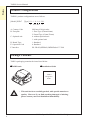
PREFACE 1. Preface 2. Note 3. Precaution 4. Product Configurations 5. Package Contents 6. CE Marking 7. RoHS Compliance 8. Documentation Conventions 9. Table of Contents Issue: 02/2006 Preface TAIKO Service Manual Preface Thank you for purchasing JCM’s TAIKO Bill Acceptor. Please be sure to read the following and any related documents thoroughly to understand the correct operation and features of this unit. Note 1. It is forbidden to copy the contents of this manual, in whole or in part, except for the user’s personal use, without the express permission of Japan Cash Machine Co., Ltd. 2. The information provided in this manual is subject to change without notice. 3. This manual has been written with care and attention to detail; however, should you find any errors or omissions, please contact Japan Cash machine Co., Ltd. and inform them of you findings. 4. Please be aware that Japan Cash Machine shall not be held liable by the user for any damages, losses or third party claims arising from any uses of this product. 5. All Company/Manufacturer names used in this manual are the registered trademarks of those companies. Precautions Host Machine Design - - We take all possible measures to ensure the quality of this unit. However, performance degradation or possible short or open circuit faults could occur at the end of a product’s life. Please ensure enough safety by the consideration of fail-safe design. Please allow sufficient space around the validator to facilitate removal of the unit or collection of bill. Mounting - 2 Do not obstruct the acceptor’s air holes so that the unit may be cooled. Do not use the e acceptor at the place where the temperature variation fluctuates widely. Do not use the acceptor in direct sunlight or incandescent lighting (15-degree or less, 3000Lx or more). Do not use/store the acceptor in a dusty area. The acceptor is for indoor use only. Do not use the acceptor outside. Do not use the acceptor in a place where chemical vapor is present. When using the acceptor in a place where the air is subject to the car exhaust emission or cigarette smoke, please clean and maintain the acceptor at regular intervals. © 2006 Japan Cash Machine Co.Ltd. All rights reserved. TAIKO Service Manual Preface Wiring - When installing the TAIKO unit or wiring the harness, be sure the power harness is unplugged from the power terminal to avoid unit damage. When wiring the harness to TAIKO unit, please use in the specified power range and pin assignment. If not, it may cause unit damage. Be sure to connect the power harness properly. If not, incorrectly-input/output may occur by contact failure. Do not give the power harness a strong pull, otherwise the power harness will break. Operation - When opening the Upper/Lower lid, be sure to remove the power to the TAIKO unit. Otherwise your fingers get caught in the roller. When closing the Upper lid, be careful not to get your finger caught in the lid. Do not modify the TAIKO unit. Doing so may damage the unit. High impact to the TAIKO unit or dropping unit may damage to the unit. Do not wipe the TAIKO unit or the inside with thinner or organic solvent. Do not add moisture or liquid to the TAIKO unit. Do not use the acceptor out of the operation Temperature/Humidity range. The following bills might be not accepted by TAIKO unit properly or cause bill jam or unit damage. a. Bills with stain, wear, wetness, tear or excessive wrinkles. b. Dog-eared bills c. Bills with incorrect cut dimensions or printing displacement d. Bills with smear of oil or foreign object Disposal - When this unit is disposed off, it should be done so according to your country’s regulations for similar types of industrial waste. © 2006 Japan Cash Machine Co.Ltd. All rights reserved. 3 Preface TAIKO Service Manual Product Configurations TAIKO’s product configurations are as follows. [Model] PUB-7 [Type] *** - 1 0 1 0 - X4 A BCDE F A. Country Code B. Faceplate C. Optional unit D. Board Type E. Operation Code F. Interface ISO based 3 digit codes 1: Euro Type (83mm/68mm) 2: Pound Type (83mm/76mm) 0: without optional unit 1: with optional unit 1: Standard 0: Standard X4: ID-003(SERIAL)/MDB/Pulse/CC-Talk Package Contents TAKO’s packaging contains the items listed below. TAIKO unit Installation Guide TAIKO Integration Guide - This unit has been carefully packed, with special attention to quality. However if you find anything damaged of missing, please contact your local distributor immediately. © 2006 Japan Cash Machine Co.Ltd. All rights reserved. 4 TAIKO Service Manual Preface CE Marking Note The TAIKO is a CE marked products. For details, contact JCM. RoHS Compliance The TAIKO is a RoHS Compliant products. The following six kind of hazardous substances restricted by RoHS are NOT contained in the TAIKO unit. nRestricted Hazardous Substances - Plumbum - Mercury - Cadmium - Chromium Hexavalent - PBB - PBDE Documentation Conventions The list below describes the documentation convertions used in this manual. Icon/Mark Descriptions This icon indecates important information or procedures that must be followed for correct and risk-free unit operation. This icon indicates useful or recommended supplemental information. 1. 2…. This indicates steps ina procedure. Be sure to perform these steps in the order given. See=> This indicates related information to refer. * This indicates useful or important supplemental inforamation - All brand names and product names are trademarks or registered trademarks of their respective companies. © 2006 Japan Cash Machine Co.Ltd. All rights reserved. 5 Preface TAIKO Service Manual Table of Contents PREFACE Preface ............................................................................................................................. 2 Note .................................................................................................................................. 2 Precautions ...................................................................................................................... 2 Package Contents ........................................................................................................... 4 Product Configurations ................................................................................................. 4 CE Marking Note ........................................................................................................... 5 RoHS Compliance .......................................................................................................... 5 Documentation Conventions ......................................................................................... 5 CHAPTER 1 Introduction 1-1. Main Features ....................................................................................................... 1-2 1-2. Prior to Use ........................................................................................................... 1-3 1-3. Parts Name............................................................................................................ 1-4 1-4. System Configuration .......................................................................................... 1-5 1-5. Operation Flow Chart ......................................................................................... 1-6 CHAPTER 2 Specifications 2-1. Specifications ........................................................................................................ 2-2 2-1-1. Basic Specifications .......................................................................................................... 2-2 2-1-2. Electrical Specifications ................................................................................................... 2-2 2-1-3. Environmental Specifications .......................................................................................... 2-2 2-1-4. Structural Specifications .................................................................................................. 2-3 2-2. Connector .............................................................................................................. 2-4 2-2-1. Interface Connector ......................................................................................................... 2-4 2-3. Pin Assignment ..................................................................................................... 2-4 2-3-1. Interface Connector Pin Assignment ............................................................................. 2-4 2-4. Interface Circuit ................................................................................................... 2-5 2-5. Outline Dimensions .............................................................................................. 2-6 2-6. Panel Cut Dimensions .......................................................................................... 2-6 2-7. DIP Switch Setting ............................................................................................... 2-7 2-7-1. Basic Setting ...................................................................................................................... 2-7 2-7-2. Special Setting ................................................................................................................... 2-8 © 2006 Japan Cash Machine Co.Ltd. All rights reserved. 6 TAIKO Service Manual Preface CHAPTER 3 Installation/Operation 3-1. Installing/Removing ............................................................................................. 3-2 3-2. Wiring.................................................................................................................... 3-5 3-2-1. Recommended Parts ........................................................................................................ 3-5 3-2-2. Wiring Procedure ............................................................................................................. 3-5 3-3. Clearing Bill JAM ................................................................................................ 3-6 CHAPTER 4 Download/Adjustment 4-1. Download ............................................................................................................. 4-2 4-1-1. Requirements .................................................................................................................... 4-2 4-1-2. Installing Downloader ..................................................................................................... 4-2 4-1-3. Connecting Procedure ...................................................................................................... 4-3 4-1-4. Download Procedure ........................................................................................................ 4-3 4-2. Adjustment ........................................................................................................... 4-5 4-2-1. Requirements .................................................................................................................... 4-5 4-2-3. . Adjustment Procedure ................................................................................................... 4-5 4-3. Palm ...................................................................................................................... 4-7 4-3-1. Requirement ...................................................................................................................... 4-7 4-3-2. Installing File Converter (PdbConvEN.exe) .................................................................. 4-7 4-3-3. Converting Software Program ....................................................................................... 4-8 4-3-4. Download Procedure ........................................................................................................ 4-9 CHAPTER 5 Trouble Shooting/Maintenance 5-1. Error Code ........................................................................................................... 5-2 5-1-1. Error Code ........................................................................................................................ 5-2 5-2. Trouble Shooting ................................................................................................. 5-2 5-2-1. General Troubles .............................................................................................................. 5-2 5-2-2. Adjustment Troubles ........................................................................................................ 5-4 5-2-3. Communication Troubles ................................................................................................ 5-4 5-3. Test Mode (Diagnostics) ...................................................................................... 5-5 5-3-1. DIP Switch Setting List ................................................................................................... 5-5 5-3-2. Test Procedure ................................................................................................................. 5-5 5-3-3. DIP Switch Test Details ................................................................................................... 5-5 5-3-4. Transport Motor Forward Rotation Test ...................................................................... 5-6 5-3-5. Transport Motor Reverse Rotation Test ....................................................................... 5-6 5-3-6. Aging .................................................................................................................................. 5-7 5-3-7. Solenoid Test .................................................................................................................... 5-8 5-3-8. Accepting Test .................................................................................................................. 5-8 5-4. Cleaning ................................................................................................................ 5-9 5-5. Maintenance Tool List ....................................................................................... 5-10 5-6. Support ................................................................................................................ 5-11 © 2006 Japan Cash Machine Co.Ltd. All rights reserved. 7 Preface TAIKO Service Manual CHAPTER 6 Replacement Procedures 6-1. Replacement of Faceplate Guide ........................................................................ 6-2 6-2. Replacement of CPU Board ................................................................................ 6-3 6-3. Replacement of Sensor Board ............................................................................. 6-4 6-4. Replacement of Encoder Board/Motor Unit...................................................... 6-8 6-5. Replacement of Solenoid ..................................................................................... 6-9 CHAPTER 7 Exploded View/Parts List 7-1. Exploded View ...................................................................................................... 7-2 7-2. Parts List ............................................................................................................... 7-3 © 2006 Japan Cash Machine Co.Ltd. All rights reserved. 8