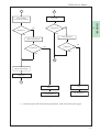
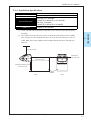
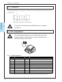
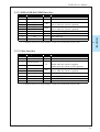
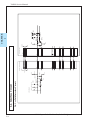
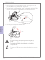
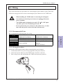
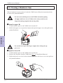
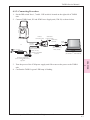
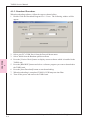
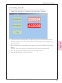
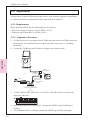
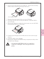
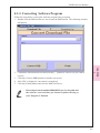
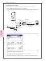
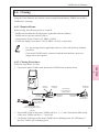
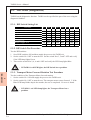
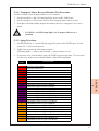
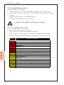
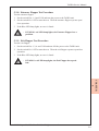
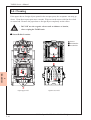
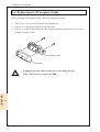
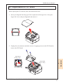
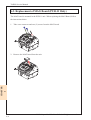
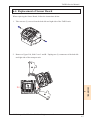
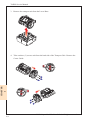
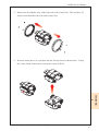
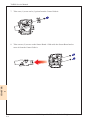
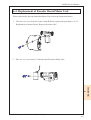
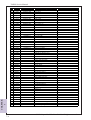
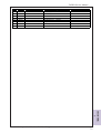
1
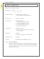
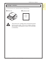
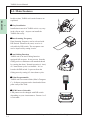
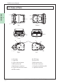
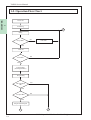
Service Manual Issue: 04/2007 Preface TAIKO Service Manual Preface Thank you for purchasing JCM’s TAIKO Bill Acceptor. Please be sure to read the following and any related documents thoroughly to understand the correct operation and features of this unit. Note 1. It is forbidden to copy the contents of this manual, in whole or in part, except for the user’s personal use, without the express permission of Japan Cash Machine Co., Ltd. 2. The information provided in this manual is subject to change without notice. 3. This manual has been written with care and attention to detail; however, should you find any errors or omissions, please contact Japan Cash machine Co., Ltd. and inform them of you findings. 4. Please be aware that Japan Cash Machine shall not be held liable by the user for any damages, losses or third party claims arising from any uses of this product. 5. All Company/Manufacturer names used in this manual are the registered trademarks of those companies. Precautions Machine Design - We take all possible measures to ensure the quality of this unit. However, performance degradation or possible short or open circuit faults could occur at the end of a - product’s life. Please ensure safety by sufficiently implementing a fail-safe design. Allow sufficient space around the unit to facilitate the collection of banknotes and cleaning of jams. Installation - Do not use the acceptor outside of the operation temperature and humidity ranges - specified in this guide. Do not use the acceptor in locations that will obstruct the acceptor’s air holes and cause the unit to become hot. - Do not use the acceptor in locations with extreme temperature fluctuations. Do not use the acceptor in direct sunlight or incandescent lighting (3000 Lx or greater at a 15 degrees angle or less). - Do not use or store the acceptor in locations with high levels of dust. - The acceptor is for indoor use only; do not use it outside. Do not use the acceptor in locations where chemical vapor is present. © 2006 Japan Cash Machine Co.Ltd. All rights reserved. 2 TAIKO Service Manual Preface - When using the acceptor in a location where the air is subject to the car exhaust emissions or cigarette smoke, be sure to clean and maintain the unit at regular intervals. Wiring - When installing the TAIKO unit or connecting the wiring harness, make sure that the power harness from the power terminal. - When connecting the wiring harness to the TAIKO unit, be sure to confirm the rated - voltage and pin assignments. Failure to do so may result in damage to the unit. Be sure to connect the power harness properly. Failure to do so may result in incorrect input/output due to contact failure. - Do not pull on the power harness with undue force, as that may cause the harness to break. Operation - Be sure to turn off the power to the TAIKO unit when opening the upper and lower covers. Failure to do so may result in your fingers becoming caught in the moving roller. - Be careful not to get your finger caught when closing the upper cover. Do not modify the TAIKO unit. Doing so may damage the unit. - Do not expose the TAIKO unit to strong impacts or drop the unit as doing so may - damage the unit. Do not wipe the TAIKO unit, either outside or inside, with thinner or organic solvent. - Do not allow moisture or liquid to enter the TAIKO unit. - Do not store the acceptor outside of the specified storage temperature and humidity - ranges. The following banknotes might be not accepted properly by the TAIKO unit or may cause a jam or damage to the unit. a. Banknotes with stain, wear, tears or excessive wrinkles, or that are wet or damp. b. Dog-eared or creased banknotes c. Banknotes with incorrect cut dimensions or printing displacement d. Banknotes with oil smear of oil or foreign objects Disposal - Disposal of this unit should be accomplished in accordance with your country’s regulations for similar types of industrial waste. © 2006 Japan Cash Machine Co.Ltd. All rights reserved. 3 Preface TAIKO Service Manual Product Configurations TAIKO unit’s are configured as follows. [Model] PUB-* [Type] *** - * * * 0 - X4 A A. Validation Method B C D E F G 7: Optical/Transparency/Reflection 11: Optical/Transparency/Reflection/MAG B. Country Code ISO based 3-digit codes C. Faceplate Type 0: Withdout faceplate 1: Acceptable Bill Width 82mm/67mm 2: Acceptable Bill Width 82mm/75mm 3: Acceptable Bill Width 82mm/71mm 5: Acceptable Bill Width 66mm D. Optional Unit 0: Without optional unit 1: With interface pin assignment conversion harness (ccTalk-compatible) E. Board Type 1: Standard 2: Interface pin assignment (ccTalk-compatible) F. Operation Code 0: Standard G. Interface X4: SERIAL(ID-003)/MDB/PULSE/ccTalk Example: PUB-7 EUR-1020-X4 Indicates the TAIKO model Bill Acceptor with Optical/Transparency Reflection Type, Type 1 faceplate, Euro software, no optional unit, interface pin assignment (ccTalk-compatible) type board, standard operation code, and an Serial(ID-003)/ MDB/Pulse/ccTalk interface. © 2006 Japan Cash Machine Co.Ltd. All rights reserved. 4 TAIKO Service Manual Preface Package Contents The following items are contained within the TAIKO Package. TAIKO unit Installation Guide TAIKO Integration Guide - This unit has been carefully packed, with special attention taken in regard to quality. However if you happen to find anything damaged of missing, please contact your local distributor immediately. © 2006 Japan Cash Machine Co.Ltd. All rights reserved. 5 Preface TAIKO Service Manual CE Marking Note DECLARATION OF CONFORMITY MANUFACTURER Name : JAPAN CASH MACHINE CO., LTD. Address : 3-15, 2-chome, Nishiwaki, Hirano-ku, Osaka, 547-0035 Japan Phone : +81-6-6703-8405 Fax : +81-6-6704-7843 DETAILS OF PRODUCT : BILL ACCEPTOR MODEL TYPES : PUB-7, PUB-11 THIS PRODUCT CONFORMS TO THE ESSENTIAL REQURIEMENTS OF Electromagnetic Compatibility Directive Amended by Low Voltage Directive : 89/336/EEC 92/31/EEC, 93/68/EEC 73/23/EEC Amended by 93/68/EEC and is supported by the following applicable standards EN61000-6-1 : 2001 EN61000-4-2 : 1995+A1 : 1998+A2 : 2001 EN61000-4-3 : 2002+A1 : 2002 EN61000-4-8 : 1993+A1 : 2001 EN61000-6-3 : 2001 EN55022 : 1994+A1 : 1995+A2 : 1997(ClassB) EN60950-1 : 2001+A11 : 2004 First Edition Authorized signatory on behalf of the responsible person Tatsuya Urata Name/Signature : Tatsuya Urata/ Date : December 1, 2006 Position : Director and executive officer, general manager manufacturing division Germany Office Address : Mundelheimer Weg 60, 40472 Dusseldorf, Germany Phone : +49-211-530645-0 Fax : +49-211-530645-65 © 2006 Japan Cash Machine Co.Ltd. All rights reserved. 6 TAIKO Service Manual Preface RoHS Compliance The TAIKO is a RoHS Compliant products. The following six kind of hazardous substances restricted by RoHS are NOT contained in the TAIKO unit. nRestricted Hazardous Substances - Plumbum - Mercury - Cadmium - Chromium Hexavalent - PBB - PBDE Documentation Conventions The list below describes the documentation convertions used in this manual. Icon/Mark Descriptions This icon indecates important information or procedures that must be followed for correct and risk-free unit operation. This icon indicates useful or recommended supplemental information. 1. 2…. This indicates steps in a procedure. Be sure to perform these steps in the order given. See=> This indicates related information to refer. * This indicates useful or important supplemental inforamation - All brand names and product names are trademarks or registered trademarks of their respective companies. © 2006 Japan Cash Machine Co.Ltd. All rights reserved. 7 Preface TAIKO Service Manual Table of Contents Preface Preface ............................................................................................................................. 2 Note .................................................................................................................................. 2 Precautions ...................................................................................................................... 2 Product Configurations ................................................................................................. 4 Package Contents ........................................................................................................... 5 CE Marking Note ........................................................................................................... 6 RoHS Compliance .......................................................................................................... 6 Documentation Conventions ......................................................................................... 6 Chapter 1 Introduction 1-1. Main Features ....................................................................................................... 1-2 1-2. Prior to Use ........................................................................................................... 1-3 1-3.Parts Name............................................................................................................. 1-4 1-4. System Configuration .......................................................................................... 1-5 1-5. Operation Flow Chart ......................................................................................... 1-6 Chapter 2 Specifications 2-1. Specifications ........................................................................................................ 2-2 2-1-1. Basic Specifications .......................................................................................................... 2-2 2-1-2. Electrical Specifications ................................................................................................... 2-2 2-1-3. Environmental Specifications .......................................................................................... 2-2 2-1-4. Structural Specifications .................................................................................................. 2-3 2-2. Connector .............................................................................................................. 2-4 2-3. Pin Assignment ..................................................................................................... 2-4 2-3-1. SERIAL(ID-003)/MDB/PULSE Interface ..................................................................... 2-4 2-3-2. ccTalk Interface ................................................................................................................ 2-5 2-4. Interface Circuit ................................................................................................... 2-6 2-5. Outline Dimensions .............................................................................................. 2-7 2-6. DIP Switch Setting ............................................................................................... 2-8 2-6-1. Basic Setting ...................................................................................................................... 2-8 2-6-2. Special Setting ................................................................................................................... 2-9 © 2006 Japan Cash Machine Co.Ltd. All rights reserved. 8 TAIKO Service Manual Preface Chapter 3 Installation / Operation 3-1. Installing/Removing ............................................................................................. 3-2 3-2. Wiring.................................................................................................................... 3-5 3-2-1. Recommended Parts ........................................................................................................ 3-5 3-2-2. Wiring Procedure ............................................................................................................. 3-5 3-3. Clearing Bill JAM ................................................................................................ 3-6 Chapter 4 Download / Adjustment 4-1. Download .............................................................................................................. 4-2 4-1-1. Requirements .................................................................................................................... 4-2 4-1-2. Connecting Procecedure .................................................................................................. 4-2 4-1-3. Download Procedure ........................................................................................................ 4-3 4-1-4. Writing Serial No. ............................................................................................................. 4-4 4-2. Adjustment ............................................................................................................ 4-5 4-2-1. Requirements .................................................................................................................... 4-5 4-2-2. Adjustment Procedure ..................................................................................................... 4-5 4-3. Palm ....................................................................................................................... 4-7 4-3-1. Requirement ...................................................................................................................... 4-7 4-3-2. Installing File Converter (PdbConvEN.exe) .................................................................. 4-7 4-3-3. Converting Software Program ....................................................................................... 4-8 4-3-4. Download Procedure ........................................................................................................ 4-9 4-4. Cloning ................................................................................................................ 4-10 4-4-1. Required Items ............................................................................................................... 4-10 4-4-2. Cloning Procedures ........................................................................................................ 4-10 Chapter 5 Trouble Shooting / Maintenance 5-1. Error Code ............................................................................................................ 5-2 5-1-1. Error Code ........................................................................................................................ 5-2 5-2. Trouble Shooting .................................................................................................. 5-2 5-2-1. General Troubles .............................................................................................................. 5-2 5-2-2. Adjustment Troubles ........................................................................................................ 5-4 5-2-3. Communication Troubles ................................................................................................ 5-5 5-3. Test Mode (Diagnostics) ....................................................................................... 5-6 5-3-1. DIP Switch Setting List .................................................................................................... 5-6 5-3-2. DIP Switch Test Procedure .............................................................................................. 5-6 5-3-3. Transport Motor Forward Rotation Test Procedure .................................................... 5-6 5-3-4. Transport Motor Reverse Rotation Test Procedure ...................................................... 5-7 5-3-5. Aging Procedure ............................................................................................................... 5-7 5-3-6. Solenoid Test Procedure ................................................................................................... 5-8 5-3-7. Accepting Test Procedure ................................................................................................ 5-8 5-3-8. Entrance Flapper Test Procedure ................................................................................... 5-9 5-3-9. Exit Flapper Test Procedure ........................................................................................... 5-9 © 2006 Japan Cash Machine Co.Ltd. All rights reserved. 9 Preface TAIKO Service Manual 5-4. Cleaning .............................................................................................................. 5-10 5-5. Maintenance Tool List ....................................................................................... 5-11 5-6. Support ................................................................................................................ 5-12 Chapter 6 Replacement 6-1. Replacement of Faceplate Guide ........................................................................ 6-2 6-2. Replacement of CPU Board ................................................................................ 6-3 6-3. Replacement of MAG Board ............................................................................... 6-4 6-4. Replacement of Sensor Board ............................................................................. 6-5 6-5. Replacement of Encoder Board/Motor Unit...................................................... 6-9 6-6. Replacement of Solenoid ................................................................................... 6-10 Chapter 7 Exploded View / Parts List 7-1. Exploded View ...................................................................................................... 7-2 7-2. Parts List ............................................................................................................... 7-3 © 2006 Japan Cash Machine Co.Ltd. All rights reserved. 10 1 Chapter Introduction 1-1. Main Features 1-2. Prior to Use 1-3. Parts Name 1-4. System Configuration 1-5. Operation Flow Chart Issue: 10/2006 TAIKO Service Manual 1-1. Main Features CHAPTER 1 In this section, TAIKO unit’s main features are explained. Easy Installation Installation/removal of TAIKO unit is very easy in the clip-on style. Anyone can install the TAIKO unit easily. Data Scanning Frequency Data Scanning frequency can be selected with DIP Switch. Normal scan (once) or twice is selectable by DIP switch. The acceptance rate can be improved by setting it twice. Anti-fishing Function TAIKO unit is an Anti-Fishing functionequipped bill acceptor. It can prevent from the fishing such as a banknote with attached thread by rotating the dram. Normal operation (1 time) or 5 times dram cycles is selectable. It is selected with DIP switch. It prevent from the fishing more by setting it 5 times dram cycles. Palm Programmable TAIKO unit can connect Palm (Palm’s Tungsten C). Software program can be downloaded from palm easily at the field. LED Pattern Selectable LED pattern can be changed with DIP switch depending on your circumstances. Pattern 1 or 2 is selectable. © 2006 Japan Cash Machine Co.Ltd. All rights reserved. 1-2 TAIKO Service Manual 1-2. Prior to Use Be sure to follow these steps when creating the project for TAIKO unit. 1 Before using TAIKO unit, check the all required hardware is present and read all specification, wiring, and installation infromation. See => Chapter 2 Specifications or Chapter 3 Installation/Operation 2. Panel Cut Out Creat the panel cut out on the door to install the TAIKO unit. See => 2-6. Panel Cut Dimensions 3. Setting Set the DIP switch depending on the connected machine or the features of TAIKO unit you want to use. See => 2-7. DIP Switch Settings 4. Installation Install the TAIKO unit and connect the harness with the mashine. See=> Chapter 2 Specifications, or Chapter 3 Installation/Operation 5. Operation Turn on the power to the TAIKO unit. © 2006 Japan Cash Machine Co.Ltd. All rights reserved. 1-3 CHAPTER 1. Preperation TAIKO Service Manual 1-3. Name of Parts CHAPTER 1 A D C E B Bottom Top G F Rear Front I H K L M J J Right Left A. Faceplate C. Upper lid E. Lower lid lock button G. Bill ejection slot I. Maintenance connector K. Upper lid open/close button M. DIP switches B. LED lamp D. Lower lid F. Bill insertion slot H. Interface connector J. Faceplate installation guide L. Optional connector © 2006 Japan Cash Machine Co.Ltd. All rights reserved. 1-4 TAIKO Service Manual 1-4. System Configuration The following diagram represents the standard items can be connected to the TAIKO unit. Maintenace Connector Interface Connector 1 Palm’ s Tungsten C TAIKO Harness B (EDP# 116488, Part# 3280-03-11) PC (Windows 98SE/2000/XP) TAIKO Harness A (EDP# 127527, Part# 3280-05-54) JCM Power Supply Unit (EDP# 116125, Part# VM-30) Harness *1 Host Machine (Game Machine etc.) *1 Communication harness needs to be prepared by custmer. © 2006 Japan Cash Machine Co.Ltd. All rights reserved. 1-5 CHAPTER TAIKO Unit TAIKO Service Manual 1-5. Operation Flow Chart CHAPTER 1 Power ON Initializing B Idling NO Accept Bill? LED OFF YES LED ON NO Insert Bill? YES Transport Bill (Scanning Bill Date) Stop Feeding Bill Validation OK? NO YES Accepted Bill? NO YES Output Denomi Signal A D © 2006 Japan Cash Machine Co.Ltd. All rights reserved. 1-6 TAIKO Service Manual A D Carry Out Bill (Carry Out to Cashbox) Reject Bill Completed 㧫 YES YES Retry Rejection Retry Carrying Out NO Completed? NO Completed? YES YES B Output VEND Signal Completed B Stop LED Red Blink *1 *1 Stop LED Red Blink *1 Turn the pouwer OFF and clear the jammed bill. Then turn on the power again. © 2006 Japan Cash Machine Co.Ltd. All rights reserved. 1-7 CHAPTER NO 1 Completed? NO TAIKO Service Manual CHAPTER 1 NOTE © 2006 Japan Cash Machine Co.Ltd. All rights reserved. 1-8 TAIKO Service Manual 2 Chapter Specifications 2-1. Specifications 2-2. Connector 2-3. Pin Assignment 2-4. Interface Circuit 2-5. External Dimensions 2-6. DIP Switch Settings Issue: 04/2007 TAIKO Service Manual 2-1. Specifications 2-1-1. Basic Specifications Acceptable Bankenote Insertion Direction *1 Accepting Rate *1 Validation Method CHAPTER 2 Anti-Fishing Mechanism Interface *2 Escrow LED *2 *1 *2 Length: 120 mm to 160 mm Width: 62 mm to 82 mm 4-way 95% or higher PUB-7: Optical/Transparency/Reflection PUB-11: Optical/Transparency/Reflection/MAG Lever and optical sensor combination ccTalk/Serial(ID-003)/MDB/Pulse 1 banknote LED lamp (upper potion of faceplate) Full-color lightning (gradation/solid) May differ depending on the software for your country. For details, refer to the Software Information Sheet. Can be selected using the DIP switches. See=> 2-7. DIP Switch Setting 2-1-2. Electrical Specifications Power Supply Voltage 12V DC ±5 % Standby: Approx. 0.1 A Rated Power Consumption Operation: Approx. 0.5 A Max: Approx. 1.4 A (Max. 300 ms) 2-1-3. Environmental Specifications Operation Temperature *1 5o C to 50o C o o Storage Temperature -20 C to 60 C Operation Humidity *1 20%RH to 85%RH (No condensation) Storage Humidity 20%RH to 85%RH (No condensation) Avoid direct sunlight Interior lighting must be incandescent lamp Light Disturbande Angle: 15 dgrees or more Illumination: 3000 Lx or less Installation For indoor use only *1 The overall operation temperature and humidity range is as follows. (RH%) 35oC / 85RH% 100 90 80 70 60 50oC / 40RH% Ambient temperature humidity range 50 40 30 20 10 0 0 5 10 15 20 25 30 35 40 45 50 55 60 (oC) © 2006 Japan Cash Machine Co., Ltd.. All rights reserved. 2-2 TAIKO Service Manual 2-1-4. Installation Specifications Installation *1 Weight External Dimentions Cahsbox *2 *1 2 Allow 100 mm above the unit to open the lid for removal of the unit from the faceplate. The cashbox must be 100 mm or more in depth from the bottom of the TAIKO unit, 200 mm or more in depth from the rear of the unit and 100 mm or more in width. Both sides of the cashbox must be higher than the position of the bill ejection slot. 100 mm or more Position of bill ejection slot Depth from rear of unit 200 mm or more Width 100 mm or more Depth from bottom of unit 100 mm or more Cashbox Side Rear © 2006 Japan Cash Machine Co., Ltd. All rights reserved. 2-3 CHAPTER *2 Door holizontal mounting (No vibration) Approx. 0.6 kg With Type 1/2/3 faceplate: 124mm (W) x 88mm (H) x 145.2mm (D) With Type 5 faceplate: 124mm (W) x 88mm (H) x 143mm(D) Supplied by the customer TAIKO Service Manual 2-2. Connector The following diagram is the interface connector as viewed from the acceptor side or from a relay board. CHAPTER 2 Box Type Plug XG4C-1034 (Omron) - If a relay board is attached to the TAIKO unit, do not attempt to remove it. 2-3. Pin Assignment - The following pin assignment is for TAIKO units with a blue JCM logo label. If the logois black, the pin assignment may differ. For details, contact JCM. Blue Black 2-3-1. ccTalk Interface Pin No. 1 2 3 4 5 6 7 8 9 10 *1 Signal Name ccT alk+ NC NC NC NC NC Vcc Vss NC NC I/O *1 Function IN/OUT ccT alk Send/Receive Line Not Connected Not Connected Not Connected Not Connected Not Connected 12V DC Power Supply Power Supply GND Not Connected Not Connected Conditions for the I/O (Input/Output) column are from the Bill Acceptor side. © 2006 Japan Cash Machine Co., Ltd.. All rights reserved. 2-4 TAIKO Service Manual 2-3-2. SERIAL(ID-003)/MDB Interface I/O *1 Function Not Connected Not Connected Data Send Line IN (Active when the current is applied) Data Receive Line OUT (Active when the current is applied) 12V DC Power Supply Power Supply GND Not Connected Not Connected Conditions for the I/O (Input/Output) column are from the Bill Acceptor side. 2 *1 Signal Name NC NC RXDRXD+ T XDT XD+ Vcc Vss NC NC 2-3-3. Pulse Interface Pin No. 1 2 Signal Name NC NC 3 Enable/Disable (-) 4 Enable/Disable (+) 5 6 7 8 9 10 Vend(-) Vend(+) Vcc Vss NC NC *1 I/O *1 Function Not Connected Not Connected Enable/Disable Signal Input Line In (Enable when the current is applied. Disable when the current is NOT applied.) PULSE Signal Output Line Out (Active when the current is applied.) 12V DC Power Supply Power Supply GND Not Connected Not Connected Conditions for the I/O (Input/Output) column are from the Bill Acceptor side. © 2006 Japan Cash Machine Co., Ltd. All rights reserved. 2-5 CHAPTER Pin No. 1 2 3 4 5 6 7 8 9 10 22K 9 HC14 IC1D DC5V 22K DC5V ccTalk (Example) 8 10K 2SC2712Y 47K RB520S-30 1SS400 DC5V 2-4-1. ccTalk Interface Circuit GND 1SS400 10K DC12V Power GND DC12V Reserve Reserve 3 4 5 6 3 4 5 6 Reserve Reserve Reserve 2 2 NC ccTalk Reserve 9 1 8 12V±5% GND/ccTalk CN1 7 10 ccTalk GND/ccTalk 12V±5% PW12V GND R1 10K GND PW12V D20 ISS400 ACCEPTOR PUB-7 10 9 1 8 7 CONTROL BOARD(Example) 3 2-6 4 2-4. Interface Circuit TR 1B UMH9 N 5 4 IC1B 3 22K R14 D5V D5V 22K R12 SN74LV 14A D5V D17 RB520S-30 D18 1SS400 CHAPTER 2 TAIKO Service Manual © 2006 Japan Cash Machine Co., Ltd.. All rights reserved. © 2006 Japan Cash Machine Co., Ltd. All rights reserved. 2-7 HC14 IC1D 8 5 3 HC14 IC1C HC14 IC1B 4 MAX 9600bps 6 HC14 IC1A 2 104uS 52uS 10K GND DC5V TYP=10mA 10mA (5mA to 15mA) DC12V GND * At leaset 5mA is necessary 2SK1580 1 GND 1SS400 10K DC12V RL=470Ω (1KΩVQΩ) 2SC2712Y 47K RB520S-30 1SS400 DC5V MDB/ID003/PULSE(Example) 22K 9 DC5V 22K DC5V CC-TALK (Example) GND DC12V 3 4 5 TXD - TXD + MDB/ID003 /PULSE RXD - RXD + 3 4 5 6 2 Reserve 2 6 10 9 1 8 Reserve NC TXD - TXD + Reserve Reserve NC ccTalk + GND 12V±5% RXD - RXD + MDB/ID003 /PULSE CN1 7 10 9 ccTalk + GND 8 1 12V±5% 7 D21 1SS400 R10 1K 1/4W D19 1SS400 C1 100pF PWGND PW12V PS2811(K) 3 2 4 IC1B R24 470Ω 5 3 IC1D SN74LV14A 8 9 SN74LV14A D5V R15 22K IC1C 5 6 DGND R9 1K 1/4W PW12V D5V C2 100pF PWGND 4 PC2 2 1 TR 2B UMH9 N PS2811(K) PC 1 TR 1B UMH9 N 5 22K R14 D5V D5V 22K R12 SN74LV 14A D5V D17 RB520S-30 D18 1SS400 1 3 4 GND R1 10K PW12V PWGND PW12V D20 ISS400 ACCEPTOR PUB-7 3 4 CONTROL BOARD(Example) 3 4 CHAPTER 2 2-4-2. Serial(ID-003)/MDB Interface Circuit TAIKO Service Manual 5 3 HC14 IC1A 2 1 HC14 IC1C 6 GND 2SK1580 DC5V TYP=10mA 10mA (5mA to 15mA) DC12V GND RL=470Ω (1KΩVQΩ) FET=ON (FET=ON ENABLE) (FET=OFF DISABLE) * At leaset 5mA is necessary. HC14 IC1B 4 Setting of DIP Switch - Pulse Width - Pulse Speed PULSE (Example) GND DC12V 3 4 5 TXD - TXD + PULSE RXD - RXD + 3 4 5 6 2 Reserve 2 6 10 9 Reserve Reserve 1 8 7 CN1 RXD - RXD + PULSE TXD - TXD + Reserve Reserve NC Reserve GND 12V±5% ACCEPTOR PUB-7 10 9 Reserve GND 8 1 12V±5% 7 CONTROL BOARD(Example) D21 1SS400 R10 1K 1/4W D19 1SS400 C1 100pF PWGND PW12V PWGND PW12V PS2811(K) 3 2 R24 470Ω 5 IC1D SN74LV14A 8 9 SN74LV14A D5V R15 22K IC1C 5 6 DGND R9 1K 1/4W PW12V D5V C2 100pF PWGND 4 PC2 2 1 TR 2B UMH9 N PS2811(K) PC 1 1 3 4 3 2-8 4 2-4-3. Pulse Interface Circuit CHAPTER 2 TAIKO Service Manual © 2006 Japan Cash Machine Co., Ltd.. All rights reserved. TAIKO Service Manual 2-5. External Dimensions 100 51 (Bill Ejection Position) 88 47.2 98 3.2 18 A* 83 (Max. Banknote Width 82) Front 2 2 to 6mm (Panel Thickness) Right Side 19 66 Rear 4-M4 50 * The length of A differs depending on the faceplate type. Type1: 68(Min. Banknote Width 67) Type2: 76(Min. Banknote Width 75) Type3: 71(Min. Banknote Width 70) Bottom © 2006 Japan Cash Machine Co., Ltd. All rights reserved. 2-9 CHAPTER Top 17.6 42.7 (Door Installation Position) 124 Unit:mm 103 (Door Installation Position) 2-5-1. When installing the Type1/Type2/Type3 faceplate with TAIKO unit TAIKO Service Manual 2-5-2. When installing the Type5 faceplate with TAIKO unit 100 125 103 (Door Installation Position) Unit:mm 3 20 67 (Acceptable Bill Width 66) 88 51(Bill Ejection Position) ‚2㨪6mm(Panel Thickness) 25.4 CHAPTER 2 38.3 (Door Installation Position) Top 45 98 Front Right Side Rear 39.6 30 11.4 Bottom © 2006 Japan Cash Machine Co., Ltd.. All rights reserved. 2-10 TAIKO Service Manual 2-6. DIP Switch Settings The communication method and various functions of the TAIKO unit can be set with the DIP switches on the left side of the unit. ON 1 2 3 4 5 6 7 8 2-6-1. Basic Settings Setting Item SW# 1 2 3 4 5 6 7 8 ON Test Mode *1 Double-Scan Mode *2 OFF Normal Mode Normal Scan Mode Reserved Five (5) drum cycles (fishing prevention) *3 Normal Operation Refer to the Software Specifications 6 OFF ON OFF ON *1 *2 *3 *4 *5 7 OFF OFF ON ON - 8 OFF OFF OFF OFF ON I/F Setting SERIAL (ID-003) MDB ccTalk (Non Encrypted) ccTalk (Encrypted) *4 PULSE *5 For details about the Test Mode, refer to 5-2-2. Test Mode. The acceptance rate will be improved but operation time will be increased if a banknote is rejected. Fishing prevention will be improved but operation time will be increased. If the encryption code become unclear, refer to 2-7-5. Encryption Code Initializing Setting Mode to initialize the encryption code. For Details about Communication Setting, refer to the Software Information Sheet. © 2006 Japan Cash Machine Co., Ltd. All rights reserved. 2-11 CHAPTER 2 Left Side TAIKO Service Manual 2-6-2. Special Settings Setting Items Denomination Accept Setting Setting Mode Inhibit Setting LED Pattern Define Pattern 1 Setting Mode Define Pattern 2 Encryption Code Initializing Setting Mode Download Mode *1 Adjustment Mode *1 CHAPTER 2 *1 SW1 ON ON ON ON SW2 OFF OFF ON OFF SW3 OFF OFF OFF ON SW4 OFF OFF OFF OFF SW5 OFF OFF OFF OFF SW6 ON ON OFF OFF SW7 OFF ON ON ON SW8 OFF OFF OFF OFF ON ON ON ON ON ON OFF OFF ON ON OFF OFF OFF OFF OFF ON ON OFF OFF OFF OFF OFF ON ON For details about Software Download and Adjustment, refer to Chapter 4 Download/Adjustment. Denomination Setting Mode Perform the accept/inhibit setting for the banknote denomination based on the software for your country. The default settings are to accept all denominations. Accept Setting ON 1 2 3 4 5 6 7 8 To perform the accept setting, set DIP switch Nos.1 and 6 to ON and then turn on the power to the TAIKO unit. After the LED flashes white, set DIP switch No.1 to OFF to enter the setting mode. Insert the denomination of banknote that you want accepted into the insertion slot. The setting is registered if the LED remains lit light blue and the banknote is returned. Insert the next denomination of banknote that you want accepted. Inhibit Setting ON 1 2 3 4 5 6 7 8 To perform the inhibit setting, set DIP switch Nos.1, 6 and 7 to ON and then turn on the power to the TAIKO unit. After the LED flashes white, set DIP switch No.1 to OFF to enter the setting mode. Insert the denomination of banknote that you want inhibit into the insertion slot. The setting is registered if the LED remains lit orange and the banknote is returned. Insert the next denomination of banknote that you want inhibited. © 2006 Japan Cash Machine Co., Ltd.. All rights reserved. 2-12 TAIKO Service Manual - The accept/reject setting for banknote denominations can be confirmed with the LED lamp. After the initial operation is performed, the LED will flash a number of times equal to the total number of banknote denominations. Blue indicates an accept setting and red means a reject setting. Example: If 5, 10 and 20 euro notes are set to be accepted and 50 and 100 euro notes to be rejected, the LED will flash the corresponding 5 times as follows: blue, blue, blue, red and red. Define Pattern 1 ON 1 2 3 4 5 6 7 8 Set DIP switch Nos.1, 2 and 7 to ON and then turn on the power to the TAIKO unit. Set DIP switch No.1 to OFF to set the LED pattern to pattern 1. Dfine Pattern 2 ON 1 2 3 4 5 6 7 8 Set DIP switch Nos.1, 3 and 7 to ON and then turn on the power to the TAIKO unit. Set DIP switch No.1 to OFF to set the LED pattern to pattern 2. Encryption Code Initializing Setting Mode When using ccTalk Communication (Encryption) Mode and the encryption code is unknown, perform the Encryption Code Initializing Setting to initialize the Encryption Code to the last 6 digits of the TAIKO serial number. ON 1 2 3 4 5 6 7 8 Set DIP switch Nos. 1 to 6 to ON (Set DIP switch Nos. 7 and 8 to OFF) and then supply the power to the TAIKO unit. Set DIP switch No. 1 to OFF to initialize the encryption code. © 2006 Japan Cash Machine Co., Ltd. All rights reserved. 2-13 CHAPTER 2 LED Pattern Setting Mode The LED pattern can be changed according to your perference. Select between pattern 1 and pattern 2. The default setting is pattern 1. TAIKO Service Manual CHAPTER 2 NOTE © 2006 Japan Cash Machine Co., Ltd.. All rights reserved. 2-14 3 Chapter Installation/ Operation 3-1. Installation/Removal 3-2. Wiring 3-3. Clearing a Banknote Jam Issue: 10/2006 TAIKO Service Manual 3-1. Installation/Removal This section describes the procedures for installing of TAIKO unit. Perform the following procedure when installing the TAIKO unit. 1. Use the panel cutting dimensions given below and create the correct size of opening required for installing the TAIKO unit to the door. Max. 4-3R 105 mm CHAPTER 3 43 mm Panel Thickness 2 mm to 6 mm 2. Hold in the upper lid open/close buttons on both sides of the TAIKO unit and open the upper lid in the direction of the arrow. © 2006 Japan Cash Machine Co.Ltd. All rights reserved. 3-2 TAIKO Service Manual 3. Grasp the TAIKO unit with your hand under the upper lid. 4. Press down slightly on the faceplate and raise up on the TAIKO unit. Slide the TAIKO unit up and back to detach it from the faceplate. back and up to detach it from the faceplate. CHAPTER 3 5. Remove the faceplate brackets (2) and the hexagonal nuts (2) from the faceplate, then insert the faceplate into the cutout from the front side of the door. 6. Fix the faceplate onto the door using the faceplate brackets (2) and the hexagonal nuts (2). Faceplate Brackets Hexagonal Nuts - Tightening the nuts with too much force can damage the faceplate. The required torque is 0.7 Nm. © 2006 Japan Cash Machine Co.Ltd. All rights reserved. 3-3 TAIKO Service Manual 7. Hold in the upper cover open/close buttons once again, open the upper cover, and grasp the TAIKO unit with your hand under the upper cover. 8. Insert the faceplate installation guide pin into the faceplate guide, and slide the TAIKO unit all the way into the guide and then push down, as indicated by the arrows. CHAPTER 3 9. Close the upper lid firmly until it clicks into place. Click - Be careful not to get your finger caught when closing the upper lid. - Confirm that the TAIKO unit and faceplate are installed securely to the door. - To remove the TAIKO unit, perform the procedure shown above in reverse order. © 2006 Japan Cash Machine Co.Ltd. All rights reserved. 3-4 TAIKO Service Manual 3-2. Wiring This section describes the procedures for connecting the power harness to the TIKO unit. Follow the steps given below when connecting the power harness to the TAIKO unit. - When installing the TAIKO unit or connecting the wiring harness, make sure that the power harness is unplugged from the power terminal. - The TAIKO unit is designed to use only 12V (+5%) DC input. Any other power level can damage the unit. - Do not pull on the power harness with undue force, as that may cause the power socket to become disconnected. 3-2-1. Recommended Parts We recommend the following parts for wiring. Socket Applicable Wires UL1061 AWG24 Socket for flat cable XG4M-1030-T (Omron) 1.27 mm pitch flat cable AWG28 UL2651/UL20012 CHAPTER 3 Semi Cover Rock Lever II Rock Lever Socket XG5M-1032-N (Omron) XG5X-0501 (Omron) XG4Z-0002 (Omron) 3-2-2. Wiring Procedure Perform the following procedure when connecting the power harness. 1. Confirm that there is no power being supplied to the power harness. 2. Connect the power harness to the TAIKO unit’s interface connector. 3. Turn on the power and confirm that the TAIKO unit operates properly. © 2006 Japan Cash Machine Co.Ltd. All rights reserved. 3-5 TAIKO Service Manual 3-3. Clearing a Banknote Jam When a banknote becomes jammed inside the TAIKO unit, follow the instructions below to remove the jammed banknote. - Be sure to turn off the power to the TAIKO unit when opening the upper and lower covers. Failure to do so may result in your fingers becoming caught in the moving roller. Open the upper lid CHAPTER 3 1. Confirm that the power to the TAIKO unit is turned off. 2. Hold in the upper cover open/close buttons and open the upper cover, then pull out the jammed banknote. - Be careful not to get your finger caught when closing the upper cover. Open the lower lid 1. Confirm that the power to the TAIKO unit is turned off. 2. Remove the faceplate from the TAIKO unit. See =>6. Installation/Removal 3. Hold in the lower cover lock release buttons and remove the lower cover, then pull out the jammed banknote. © 2006 Japan Cash Machine Co.Ltd. All rights reserved. 3-6 TAIKO Service Manual 4 Chapter Download & Adjustment 4-1. Download 4-2. Adjustment 4-3. Palm 4-4. Cloning Issue: 05/2007 TAIKO Service Manual 4-1. Download The software download procedure is described in this section. When the software has been upgraded or the TAIKO unit’s CPU board has been replaced, please download the software to the TAIKO unit. When downloading a software from Palm, please refer 4-2. Palm. 4-1-1. Requirements When downloading, the following items are required. - TAIKO unit - JCM power supply unit (Part#.VM-30, EDP#.116125) or equivalent - TAIKO harness A (Part#.3280-05-54, EDP#.127527) * - TAIKO harness B (Part#.3280-03-11, EDP#.116488) - Downloader (Download Program Ver. 1.21.exe) - Software program (Ex. P07X3102.G_S) * This harness is only for TAIKO units with a blue JCM logo label. If the logo is black, the harness may differ. For details, contact JCM. CHAPTER 4 Blue Black © 2006 Japan Cash Machine Co.Ltd. All rights reserved. 4-2 TAIKO Service Manual 4-1-2. Connecting Procedure 1. Set the DIP switch Nos.1, 7 and 8. DIP switch is located on the right side of TAIKO unit. 2. Connect TAIKO unit, PC and JCM Power Supply unit (VM-30) as shown below. Interface Connector(10 Pin) Host Machine Maintenance Connecotr(4 Pin) Maintenance Connecotr or Interface Connector To AC Power TAIKO Harness A (Part#:3280-05-54, EDP#: 127527) TAIKO Serial Port TAIKO Harness B (Part#: 3280-03-11, EDP#:116488) ID-003/CC TALK/HII Connector PC (OS: Windows(R) 98 SE/2000/XP) CHAPTER 4 JCM Power Supply Unit (Part#: VM-30, EDP#:116125) or equivalent 3. Turn the power of the JCM power supply unit ON to turn on the power to the TAIKO unit. 4. Confirm the TAIKO’s green LED lamp is flashing. © 2006 Japan Cash Machine Co.Ltd. All rights reserved. 4-3 TAIKO Service Manual 4-1-3. Download Procedure When downloading software, follow the steps as shown bellow. 1. Double Click the Download Program Ver. 1.21.exe. The following window will be appear. 2. Select your PC’s COM Port # from the Port pull down menu. CHAPTER 4 3. Select 38400 from the Baudrate pull down menu. 4. Press the [Version Check] button to display current software which is installed in the TAIKO unit. 5. Press the [BROWSE] button and select a software program you want to download to the TAIKO unit. 6. Press the [Start Download] button to start downloading. 7. When downloading is completed. TAIKO’s LED lamp turn into Blue. 8. Turn off the power and remove the TAIKO unit. © 2006 Japan Cash Machine Co.Ltd. All rights reserved. 4-4 TAIKO Service Manual 4-1-4. Writing Serial No. When replacing CPU board, follow the steps below and write Serial No.. 1. Double click SerialNo.exe and then the following window will appear. 2. Click [Read Serial Number] button and then 6-digit of current serial number will be CHAPTER 4 displayed in the box next to the button. When the CPU board is new, nothing is displayed in the box. 3. Enter 6-digit of new serial number in the input box next to the [Write Seiral Number] button. Example: If the serial number is 03050438058, enter the last 6-digit 438058. 4. Press the [Write Serial Number] button to start writing serial no. 5. Press the [Exit] button to close the window. © 2006 Japan Cash Machine Co.Ltd. All rights reserved. 4-5 TAIKO Service Manual 4-2. Adjustment You learn how to adjust TAIKO unit in this section. After software program is downloaded or CPU/Sensor Board is replaced, the TAIKO unit needs to be adjusted. 4-2-1. Requirements When adjusting TAIKO unit, the following items are required. - JCM power supply unit (Part#. VM-30, EDP#.116125) - Reference Paper (Part#.KS-070, EDP#.119581) 4-2-2. Adjustment Procedure 1. Confirm the power is not supplied to the TAIKO unit and remove the TAIKO unit from the faceplate. For details about removing the faceplate, refer to the 3-1. Installing/ CHAPTER 4 Removing. 2. Connect the TAIKO unit and JCM Power Supply unit as shown below. Host Machine Interface Connector(10 Pin) Interface Connecter or TAIKO Harness A (Part#.3280-05-54 EDP#.121797) AC Power TAIKO ID-003/CC TALK/HII Connecter JCM Power Supply Unit (Part#. VM-30, EDP#.116125) or equivalent 3. Set the TAIKO’s DIP switch Nos.1, 2 and 8 ON. The DIP switch is located on the right side of the unit. ON 1 2 3 4 5 6 7 8 4. Turn on the power to the TAIKO unit. Confirm that TAIKO’s white LED lamp is flashing. 5. Set the DIP switch No.1 OFF and confirm that TAIKO’s green LED lamp lights. © 2006 Japan Cash Machine Co.Ltd. All rights reserved. 4-6 TAIKO Service Manual 6. Insert the reference paper (KS-070) to the TAIKO unit. Then the roller start rotating and then continue to insert the reference paper all the way in. Reference Paper (KS-070) 7. When the reference paper reaches all the way in, green LED flashes. 8. Set the DIP switch No.8 OFF to start the paper adjustment. Confirm that TAIKO’s yellow LED lights. 9. When the paper adjustment is completed, the reference paper come out of the TAIKO unit automatically. Remove the reference paper. CHAPTER 4 10. Confirm the green LED lights and set the DIP switch No.8 ON to start the no paper adjustment. 11. Confirm that TAIKO’s yellow LED lights. 12. When the paper adjustment and EEPROM writing is completed successfully, confirm that TAIKO’s blue LED lights. - If the adjustment and EEPROM writing is not completed successfully, the red LED lights. Please start again from the beginning. © 2006 Japan Cash Machine Co.Ltd. All rights reserved. 4-7 TAIKO Service Manual 4-3. Palm Download procedure using Palm is described in this section. 4-3-1. Requirement When adjusting TAIKO unit, the following items are required. - Palm (Palm(R)’s Tungsten C) - TAIKO Harness B (Part#.3280-03-11, EDP#.116488) - File Converter Installer (setup.exe/SETUP.LST/PdbConvEN.CAB) - Download Program (ID003DWN.prc) - Software Program (Ex. P07X3102.G_S ) 4-3-2. Installing File Converter (PdbConvEN.exe) When downloading a software from palm, the file needs to be convert into prc format. Follow the steps below to install the File Converter (PdbConvEN.exe). 1. Save the setup.exe/SETUP.LST/PdbConvEN.CAB to your PC. 2. Double click the setup.exe to start to install. CHAPTER 4 3. Follow the instruction on the screen and complete installing. 4. PdbConvEn.exe icon is created on your PC’s desktop. © 2006 Japan Cash Machine Co.Ltd. All rights reserved. 4-8 TAIKO Service Manual 4-3-3. Converting Software Program Follow the steps below, convert the software program into prc format. 1. Double click the PdbConvEn.exe icon to start the PdbConvEn. The following window will appear. CHAPTER 4 2. Confirm the Download File tab and click the [...] button to select a file you want to convert. 3. Click the [Convert PDB] button to start the conversion. 4. After CRC is displayed, convension is completed. 5. Click the [Finish] button and close the PdbConvEn.exe. - Please import the downlader(ID003DWN.prc) for the palm and the software converted into prc format to palm referring to your Tungsten C Manual. © 2006 Japan Cash Machine Co.Ltd. All rights reserved. 4-9 TAIKO Service Manual 4-3-4. Download Procedure When downloading a software from your palm, follow the instructions below. 1. Set the TAIKO unit’s DIP switch Nos. 1, 7 and 8 ON. 2. Connect your palm with the TAIKO unit as shown below and supply the power to the TAIKO unit. Interface Connector(10 Pin) Maintenance Connector(4 Pin) Host Machine or AC Power To Maintenace Connector Interface Connecter TAIKO Harness A (Part#.3280-05-54 EDP#.121797) TAIKO TAIKO Harness B (Part#: 3280-03-11, EDP#:116488) Palm(R) Tungsten C ID-003/CC TALK/HII Connecter CHAPTER 4 JCM Power Supply Unit (Part#. VM-30, EDP#.116125) or equivalent 3. Turn on your palm and tap the DWN-03 icon. The following screen will be displayed. 4. When tapping the area (A) shown below, the software information which is currently installed in the TAIKO unit will be showed. 5. Tap the area (B) and select the software you want to download. 6. Tap the [Send] button to start downloading. 7. When the downloading is complete, the screen returns to the previous automatically. © 2006 Japan Cash Machine Co.Ltd. All rights reserved. 4-10 TAIKO Service Manual 4-4. Cloning Using the Clone Harness, the software can be copied from the Master TAIKO unit to Salve TAIKO unit. (Cloning) 4-4-1. Required Items When cloning, the following items are required. - TAIKO unit installed the cloning feature applicable software (Master) - TAIKO unit to copy the software (Slave) - Clone Harness (Part#: 3280-05-52, EDP#: 124528) - JCM Power Supply Unit (Part#: VM-30, EDP#: 116125) or equivalent - For the cloning features applicable software, refer to the Software Information Sheet. - If the master TAIKO unit is connected with the host machine, the power supply unit is not required. 4-4-2. Cloning Procedures Interface Connector Maintenace Connector AC Power Maintenace Connector Clone Harness (Part#:3280-05-52 EDP#:124528) Host Machine or CHAPTER 4 Follow the steps below to clone. 1. Connect the master TAIKO unit and the slave TAIKO unit as shown below. Interface Connector Maintenace Connector Master TAIKO Maintenace Connector Slave TAIKO TAIKO Harness A (Part#.3280-05-51, EDP#.121797) JCM Power Supply Unit (Part#. VM-30, EDP#.116125) or equivalent 2. Set the DIP switch of the master TAIKO unit Nos. 1, 2, 7 and 8 ON and the DIP switch of the slave TAIKO unit Nos. 1, 7 and 8 ON. 3. Confirm the LED lamp of the master TAIKO unit is flashing withe, the LED lamp of the slave TAIKO unit is flashing green. © 2006 Japan Cash Machine Co.Ltd. All rights reserved. 4-11 TAIKO Service Manual 4. Set the DIP switch of the master TAIKO unit No. 1 OFF to start cloning. 5. When starting cloning, the LED lamp of the master TAIKO unit lights pink, the LED of the slave TAIKO unit lights yellow. 6. When the LED lamp of the slave TAIKO unit lights blue (or flashes green), the cloning is complete. (Approx. 15 minutes) 7. Set the DIP switch of the master TAIKO unit No.1 ON. CHAPTER 4 8. When producing another clone TAIKO, turn off the power, connect another slave TAIKO unit and perform from the step 2. © 2006 Japan Cash Machine Co.Ltd. All rights reserved. 4-12 TAIKO Service Manual 5 Chapter Trouble Shooting / Maintenance 5-1. 5-2. 5-3. 5-4. 5-5. 5-6. Error Codes Trouble Shooting Test Mode (Diagnostics) Cleaning Maintenance Tool List Product Support Issue: 04/2007 TAIKO Servic e Manual 5-1. Error Codes Number of Red flashes of the LED lamp indicates the Error of TAIKO unit. LED lamp is located in the middle of the faceplate. 5-1-1. Error Codes # of Flashes 2 3 4 5 6 8 9 12 Diagnostic Description ROM error Banknote remains inside ejection slot Banknote remains inside transport path EEPROM read/write error Motor error Entrance solenoid error Exit solenoid error Fraud detected 5-2. Trouble Shooting When an error message appears or trouble is occures and the TAIKO unit does not work properly, recover the TAIKO unit following the instruction below. 5-2-1. General Troubles Recovery Action Verify the specified voltage and ground Power is not supplied to the are supplied to appropriate pins of the acceptor. interface connector. Verify if all harnesses and connectors are connected properly. Verify if the connector pin has been any Connection is wrong. bend, missing, broken. Verify if the specified voltage is supplied to the appropriate pin. See=> Chapter Acceptor is not working 2 Specifications (Acceptor does not accept Download the appropriate software to any bill) Software is not downloaded. the TAIKO unit. See=> 4-1.Download Perform Acceptance Test. See => 4-2. Test Mode (Diagnostics) If the test result is NG, replace the CPU/Sensor Board is CPU/Sensor Board. See=> Chapter 6 Corrupted. Replacement procedure After CPU/Sensor board is replaced, perform the adjustment. See=> 4-2. Adjustment CHAPTER 5 Symptom/Error Message Possible Causes © 2006 Japan Cash Machine Co.Ltd. All rights reserved. 5-2 TAIKO Service Manual Symptom/Error Message Possible Causes CHAPTER 5 Recovery Action Clean the feed or Pinch roller. See=> 6-4. Cleaning Feed or Pinch roller is If any corruption is found, replace it. spoiled with dirt or broken. See=> 6-2. Replacement of Sensor Board Verify the condition of the Feed or Feed or Pinch roller spring is Pinch roller spring and replace it as missing or loose. required. Remove the foreign objects from the JAM bill occurs often. There is any foreign objects transport path and clean. See=> 5-4. is on the transport path. Cleaning Change the faceplate guide depending Faceplate does not match on the bill width. See=> 3-3. Replace with the bill width. of Faceplate Guide The bill width is 83mm or Use the only acceptable bills. See=> larger or 62mm or less. Chapter 2 Specifications (Out of TAIKO Specifications) Remove the foreign object and clean the entrance sensor. See=> 5-4. Cleaning Entrance Sensor is not Acceptor is not working. Perform Aging. See=> 5-2-6. Aging working or there is any (Acceptor does not accept details foreign object at the any bills.) If any sensor error is found, replace entrance. the CPU/Sensor board. See=> Chapter 6 Replacement Procedure Rollers, belts and lenses is Clean the rollers, belts and lenses. soiled with dirt. See=> 5-4. Cleaning Adjust the TAIKO unit. See=> 5-4. Sensor needs to be adjusted. Cleaning After disassembled, the Adjust the TAIKO unit. See=> 5-4. TAIKO has not been Acceptance rate is low. Cleaning adjusted. Download the latest software program. The software revision is old. See=> 4-1. Download Verify if the denomination, issued year The bill that software program is not supported is is appropriate in the software information sheet. inserted. © 2006 Japan Cash Machine Co.Ltd. All rights reserved. 5-3 TAIKO Servic e Manual Symptom/Error Message Possible Causes Recovery Action Download the appropriate software Software does not match program to the TAIKO unit. See=> with the currency. 4-1. Download Set the accepting setting properly. DIP Switch setting is wrong. See=> 2-7-3. Denomination Setting The command from Host is All bills are returned. Set the command to accept. set to inhibit. CPU/Sensor failure is Replace CPU/Sensor Board. See=> occurred. Chapter 6 Replacement Procedure. Clean all sensors. See=> Cleaning Sensor needs to be cleaned Perform adjustment See=>4-2. and adjusted. Adjustment Replace the CPU board. See=> 6CPU board failure Motor rotates a few times 1. Replacement of CPU board and stop. Set the DIP Switch No.1 ON and DIP Switch setting is wrong. supply the power to the TAIKO unit. Perform the DIP Switch TEST. See=> 5-3-3. DIP Switch Test Details DIP Switch is broken. If the test result is NG, replace the Cannot enter the Test Mode. CPU board. See=> 6-1. Replace of CPU board Replace the CPU board. See=>6-1. CPU board failure Replacement of CPU board 5-2-2. Adjustment Troubles CHAPTER 5 Symptom/Error Message Possible Causes Reference paper is wrong. Adjustment Error CPU/Sensor board failure. Recovery Action Use the reference paper (KS-070) for TAIKO. Replace the CPU/Sensor board. See=> Chapter 6 Replacement Procedure © 2006 Japan Cash Machine Co.Ltd. All rights reserved. 5-4 TAIKO Service Manual 5-2-3. Communication Troubles Symptom/Error Message Possible Causes Recovery Action Set all DIP Switches OFF and DIP switch setting is wrong. supply the power to the TAIKO unit. Connector is unplugged or is Connect all connector properly. not connected properly. Verify if the connector pin is any Cannot communicate with Connector pin is broken. bend, broken or missing. Replace Host the CPU board as required. Replace the CPU board. See=> 6CPU board failure 1. Replacement of CPU board Verify if the interface is appropriate Interface is wrong. with Host. If wrong, set the interface properly. See=> 2-7. DIP Switch - When you cannot solve the problem even if you follow the instruction above, please contact JCM. See => 5-6. Support CHAPTER 5 © 2006 Japan Cash Machine Co.Ltd. All rights reserved. 5-5 TAIKO Servic e Manual 5-3. Test Mode (Diagnostics) TAIKO has the diagnostics function. TAIKO can be specified the part of the error using the diagnostic funktion. 5-3-1. DIP Switch Setting List Test Items SW1 SW2 ON ON DIP Switch Test Transport Motor Forward Rotation Test ON OFF Transport Motor Reverse Rotation Test ON ON ON OFF Sensor Test ON ON Solenoide Test ON OFF Accepting Test ON OFF Entrance Flapper Test ON ON Exit Flapper Test SW3 ON OFF OFF ON ON OFF OFF OFF SW4 ON OFF OFF OFF ON OFF ON ON SW5 ON OFF OFF OFF OFF ON ON ON SW6 ON OFF OFF OFF OFF OFF OFF OFF SW7 ON OFF OFF OFF OFF OFF OFF OFF SW8 ON OFF OFF OFF OFF OFF OFF OFF 5-3-2. DIP Switch Test Procedure Test the DIP switches. 1. Set all DIP switches ON and then supply the power to the TAIKO uit. 2. Set the switch No.1 OFF to start the test. Set the switch Nos.3, 5 and 7 OFF and verify if the LED lamp lights Green. 3. Then set the switch Nos.2, 4, 6 and 8 OFF and verify the LED lamp lights Blue. - IIf TAIKO’s red LED lights, the DIP Switch has a problem. CHAPTER 5 5-3-3. Transport Motor Forward Rotation Test Procedure Test the condition of the Transport Motor forward rotation. 1. Set the switch No.1 ON and supply the power to the TAIKO unit. 2. Set the switch No.1 OFF to start the test. The transport motor rotates forward. 3. If the Blue LED lamp blinks despite the number, the test is completed. No error is found. - If TAIKO’s red LED lamp lights, the Transport Motor has a problem. © 2006 Japan Cash Machine Co.Ltd. All rights reserved. 5-6 TAIKO Service Manual 5-3-4. Transport Motor Reverse Rotation Test Procedure Test the condition of the Transport Motor reverse rotation. 1. Set the switch No.1 and 2 ON and supply the power to the TAIKO unit. 2. Set the switch No.1 OFF to start the test. Ther transport motor rotates reverse. 3. If the Blue LED lamp blinks despite the number, the test is completed. No error is found. - If TAIKO’s red LED lamp lights, the Transport Motor has a problem. 5-3-5. Aging Procedure 1. Set the switch Nos.1, 2 and 4 ON and supply the power to the TAIKO unit. Set the switch No. 1 OFF to start the test. 2. TAIKO unit repeates the following operation. LED lamp lights => Motor rotates foward => Motor rotates reverse 3. If an sensor error is found while aging, the TAIKO stop the operation. You can specified the error of the sensor with the number of the LED lamp blinks. Sensor Position Enterance Sensor Right Enterance Sensor Left Upper Transit Sensor Lower Transit Sensor Enterance Solenoid Sensor Exit Solenoid Sensor VEND Lever Sensor Encoder Sensor Penetration (Upper to Lower) Right IR Penetration (Upper to Lower) Left IR Penetration (Upper to Lower) Right RED Penetration (Upper to Lower) Left RED Penetration (Upper to Lower) Right NIR Penetration (Upper to Lower) Left NIR Penetration (Upper to Lower) Right BLUE Penetration (Upper to Lower) Left BLUE Penetration (Lower to Upper) Right IR Penetration (Lower to Upper) Left IR Penetration (Lower to Upper) Right RED Penetration (Lower to Upper) Left RED Penetration (Lower to Upper) Right NIR Penetration (Lower to Upper) Left NIR Penetration (Lower to Upper) Right BLUE Penetration (Lower to Upper) Left BLUE CHAPTER 5 # of Flashes 1 2 3 4 5 6 7 8 1 2 3 4 5 6 7 8 1 2 3 4 5 6 7 8 © 2006 Japan Cash Machine Co.Ltd. All rights reserved. 5-7 TAIKO Servic e Manual 5-3-6. Solenoid Test Procedure Test the condition of the solenoids. 1. Set the switch Nos.1, 2, 3 and 4 ON and turn ON the power to the TAIKO unit. 2. Set the switch No.1 OFF to start the test. Then the TAIKO unit repeates the following operation. Entrance Flapper On/Off => Exit Flapper On/OFF 3. If the Blue LED lamp lights, no error is found. - If TAIKO’s red LED lights, the Solenoid has a problem. 5-3-7. Accepting Test Procedure Test the condition of the acceptance of the bils. 1. Set the switch No.1 and 5 ON and supply the power ON. 2. Set the switch No.1 OFF to start the test. Then insert the bill to the TAIKO unit. 3. If the bill is returned, the LED flashes depending on the reason for the reterning. CHAPTER 5 # of Flashes 2 3 4 5 6 8 9 12 1 4 5 7 8 9 12 13 14 15 Diagnostic Description ROM Error JAM inside Acceptor Bill remains inside transport path Adjustment Error Motor Error Entrance Solenoid Error Exit Solenoid Error Sensor operation at the abnormal timing Reject by slant insertion X-rate Error Bill Transportation Error Pattern Error Photo Level Error Reject by Inhibit Setting Magnetism Pattern Error (PUB-11 Only) Bill Length Error Ir/Red Error Reject by counterfeiting currency © 2006 Japan Cash Machine Co.Ltd. All rights reserved. 5-8 TAIKO Service Manual 5-3-8. Entrance Flapper Test Procedure Test the entrance flapper. 1. Set the switch Nos.1, 4 and 5 ON and turn the power to the TAIKO unit. 2. Set the switch No.1 OFF to start the test. Then the entrance flapper repeates open/ close operation. 3. If the Blue LED lamp lights, no error is found. - If TAIKO’s red LED lamp lights, the Entrance Flapper has a problem. 5-3-9. Exit Flapper Test Procedure Test the exit flapper. 1. Set the switch Nos.1, 2, 4 and 5 ON and turn ON the power to the TAIKO unit. 2. Set the switch No.1 OFF to start the test. Then the exit flapper repeates open/close operation. 3. If the Blue LED lamp lights, no error is found. - If TAIKO’s red LED lamp lights, the Exit Flapper has a problem. CHAPTER 5 © 2006 Japan Cash Machine Co.Ltd. All rights reserved. 5-9 TAIKO Servic e Manual 5-4. Cleaning If the paper dust or foreign object spotted in the acceptor parts, the acceptance rate may go down. Clean the acceptor parts once a month. Wipe out on the sensor with lint-free cloth or cotton bud. Remove the paper dust or foreign object completely on the rollers. - DO NOT use the organic solvent such as thinner or benzin, when wiping the TAIKO unit. Sensor/Roller Location CHAPTER 5 Sensor Pinch Roller Feed Roller Open Upper Lid Open Lower Lid © 2006 Japan Cash Machine Co.Ltd. All rights reserved. 5-10 TAIKO Service Manual 5-5. Maintenance Tool List When maintenace or adjust TAIKO unit, the following parts need to be parchased. Items EDP# Part# Power Supply Unit 116125 VM-30 TAIKO Harness A 127527 3280-05-54 TAIKO Harness B 116488 3280-03-11 Clone Harness 124528 3280-05-52 Reference Paper 119581 KS-070 Description This unit is to supply the power to TAIKO unit. This harness is to connect with TAIKO unit ant Power Supply Unit. This harness is to connect with PC and TAIKO unit when downloding or connecting with palm. This harness is to connect with a master TAIKO and a slave TAIKO when cloning. This is a reference paper to adjust TAIKO unit. CHAPTER 5 © 2006 Japan Cash Machine Co.Ltd. All rights reserved. 5-11 TAIKO Servic e Manual 5-6. Product Support If you happen to experience any problems or errors with your TAIKO unit, or have any inquiries regarding your unit, consult with your nearest JCM contact as shown below. Please be sure to make a note of the problem points andy symptoms, or the content of your inquiry, prior to making contact. Japan Japan Cash Machine Co. Ltd. (Headquarters) 3-15, Nishiwaki 2-Chome, Hirano-ku, Osaka 547-0035 Japan Phone: +81-66-703-8406 Fax: +81-66-704-7843 URL: www.jcm-hq.co.jp Americas, Oceania JCM American Corporation 925 Pilot Road, Las Vegas, NV 89119 U.S.A. Phone: +1-702-651-0000 Fax: +1-702-644-5512 e-mail: [email protected] URL: www.jcmamerican.com CHAPTER 5 Europe, Russia, Middle East, Africa Japan Cash Machine Germany GmbH Mündelheimer Weg 60 D-40472 Düsseldorf Germany Phone: +49-211-530645-0 e-mail: [email protected] Fax: +49-211-530645-65 URL: www.jcm-germany.com UK, Ireland JCM United Kingdom Ltd. Unit B, Third Avenue, Denbigh West Business Park Bletchley, Milton Keynes, Buckinghamshire MK1 1EJ, UK Phone: +44-870-770-2863 Fax: +44-190-837-7834 e-mail: [email protected] URL: www.jcm-uk.com Asia (other than Japan) JCM Gold (HK) Ltd. Unit 1-7, 3F., Favor Industrial Centre 2-6 Kin Hong Street, Kwai Chung, N.T. Hong Kong Phone: +852-2429-7187 Fax: +852-2929-7003 URL: www.jcmgold.com.hk e-mail: [email protected] © 2006 Japan Cash Machine Co.Ltd. All rights reserved. 5-12 TAIKO Service Manual 6 Chapter Replacement Procedure 6-1. Replacement of Faceplate Guide 6-2. Replacement of CPU Board 6-3. Replacement of MAG Board (PUB-11 Only) 6-4. Replacement of Sensor Board 6-5. Replacement of Motor Unit/ Encoder Board 6-6. Replacement of Solenoid Issue: 04/2007 TAIKO Service Manual 6-1. Replacement of Faceplate Guide When replacing the Faceplate Guide, follow the instructions below. 1. Take out two (2) screws from bihind the Faceplate unit. 2. Remove a (1) Faceplate Guide from the Faceplate. 3. Insert a (1) new Faceplate Guide into the Faceplate and then tighten two (2) screws to hold the Faceplate Guide. Faceplate Guide Faceplate 6 CHAPTER - Tightening the nuts with too much force can damage the facem. plate. The necessary torque is 0.7N © 2006 Japan Cash Machine Co.Ltd. All rights reserved. 6-2 TAIKO Service Manual 6-2. Replacement of CPU Board When replacing the CPU Board, follow the instructions below. 1. Insert your fingernail into the gap of left or right side of the Upper Lid. Lift up the Upper Lid Cover with your fingernail and remove it. 2. Unplug four (4) connectors and take out two (2) tapping screws on the CPU Board to remove the CPU Board. MAG Board (PUB-11 Only㧕 6 View from the top © 2006 Japan Cash Machine Co.Ltd. All rights reserved. 6-3 CHAPTER MAG Board (PUB-11 Only㧕 TAIKO Service Manual 6-3. Replacement of MAG Board (PUB-11 Only) The MAG board is mounted in the PUB-11 unit. When replacing the MAG Board, follow the instructions below. 1. Take out a connector and two (2) screws from the MAG board. 6 CHAPTER 2. Remove the MAG board from the unit. © 2006 Japan Cash Machine Co.Ltd. All rights reserved. 6-4 TAIKO Service Manual 6-4. Replacement of Sensor Board When replacing the Sensor Board, follow the instructions below. 1. Take out two (2) screws from the both left and right side of the TAIKO unit. 2. Remove a Upper Lid, Side Cover L and R. Unplug two (2) connectors of the both left and right side of the transport unit. 6-5 CHAPTER 6 © 2006 Japan Cash Machine Co.Ltd. All rights reserved. TAIKO Service Manual 3. Remove the transport unit form the Lower Base. 4. Take out three (3) screws each from the both side of the Transport Unit. Remove the 6 CHAPTER Center Guide. © 2006 Japan Cash Machine Co.Ltd. All rights reserved. 6-6 TAIKO Service Manual 5. Remove the Feed Roller Assy of the both side of the Center Unit. Take out three (3) washers each from the both side of the Center Unit. 6. Insert the minus driver or equivalent into the encircled area as shown below. Lift up the Center Guide A and remove it from the Center Guide B. 6-7 CHAPTER 6 © 2006 Japan Cash Machine Co.Ltd. All rights reserved. TAIKO Service Manual 7. Take out a (1) screw and a (1) prism from the Center Guide A. 8. Take out two (2) screws on the Sensor Board. Slide aside the Sensor Board and re- 6 CHAPTER move it from the Center Guide A. © 2006 Japan Cash Machine Co.Ltd. All rights reserved. 6-8 TAIKO Service Manual 6-4. Replacement of Encoder Board/Motor Unit When replacing the Encoder Board and Motor Unit, follow the instructions below. 1. Take out a (1) screw from the Center Guide B (Refer replacement procedure 6. of 6-2. Replacement of Sensor Board. Remove the motor Unit. 2. Take out a (1) screw and a (1) Encoder Board from the Motor Unit. 6-9 CHAPTER 6 © 2006 Japan Cash Machine Co.Ltd. All rights reserved. TAIKO Service Manual 6-5. Replacement of Solenoid When replacing the Entrance and Exit Solenoid, follow the instructions below. 1. Take out two (2) screws from the Lower Guide and then remove the Guide Assy. 6 CHAPTER 2. Put the Lower Guide upside down and open the Lower lid pressing the Lower Lid Open/Close Button. © 2006 Japan Cash Machine Co.Ltd. All rights reserved. 6-10 TAIKO Service Manual 3. Remove two (2) Guide Levers from the Lower Guide. 4. Take out two (2) screws and then remove a (1) Entrance and a (1) Exit Solenoid. 6-11 CHAPTER 6 © 2006 Japan Cash Machine Co.Ltd. All rights reserved. TAIKO Service Manual 7 Chapter Exploded View/ Parts List 7-1. Exploded View 7-2. Parts List Issue: 04/2007 TAIKO Service Manual 7-1. Exploded View 31 88 97 45 98 123 5 9839 39 6 39 68 53 42 78 6 39 73 11 6 39 6 79 6 69 39 64 82 11 73 89 90 19 80 66 30 26 60 61 85 90 100 67 97 54 29 3 32 56 55 9 59 86 16 100 101 99 18 15 14 108 12 83 93 25 17 92 24 90 98 96 98 4 81 18 95 13 91 94 98 58 20 72 27 34 15 99 16 98 36 28 72 97 67 62 35 62 40 122 74 65 114 47 48 48 39 39 7 102 7 100 5 33 122 114 115 100 101 37 40 38 75 75 38 98 65 54 74 47 115 60 46 111 103 51 22 2 23 8 21 120 1 41 CHAPTER 7 110 22 39 6 78 78 52 6 10 6 105 8 104 39 57 106 107 50 106 71 70 39 39 6 10 10 49 44 77 10 77 109 98 52 121 © 2006 Japan Cash Machine Co.Ltd. All rights reserved. 7-2 TAIKO Service Manual 7-2. Parts List No. 1 2 3 4 5 6 7 8 9 10 11 13 14 15 16 17 18 19 20 21 22 23 24 25 26 27 28 29 30 31 32 33 34 35 36 37 38 39 40 41 42 44 45 46 48 49 50 51 Part No. TDS-04B-328 TDS-04B-327 3280-05-01 3280-05-02 3280-05-04 4045CS0101 4045CS0102 4045CS0103 4045CS0104 4045CS0105 4045CS0106 4045GE0103 4045GE0102 4045GE0106 4045AS0101 4045GE0104B 4045GE0105A 4045KS0103A 4045KS0104 4045PT0105 4045PT0103 4045PT0101A 4045RE0101 4045RE0102B 4045RE0103A 4045RE0104A 4045RE0105B 4045RE0106B 4045RE0107C 4045RE0108A 4045RE0109B 4045RE0110B 4045RE0126A 4045RE0127A 4045RE0128B 4045RE0129B 4045RE0130 4045RE0131 4045RE0132 4045RE0135A 4045RE0147 4045RE0113 4045RE0118A 4045RE0121A 4045RE0123 4045RE0124A 4045RE0125A 4045RE0136B 4045RE0158B 4045RE0161B 4045RE0164 4045RE0137 4045RE0139A 4045RE0140 4045RE0143 Description Enterance Solenoid Exit Solenoid Relay Harness (14P) PI Harness (3P) Relay Harness 2 (4P) Pinch Roller Spring (A) Pinch Roller Spring (B) Solenoid Spring M G Roller Spring Lower Guide Lock Spring Lock Spring Worm Gear Idle Gear Guide Gear Feed Roller Assy Worm Wheel Drive Gear Shutter Sensor Spring Shutter Spring Solenoid Bracket (B) Faceplate Bracket Solenoid Bracket G Box B G Box A Center Guide A Center Guide B Center Guide R Center Guide L Upper Guide Upper Guide Cover Side Cover L Side Cover R Guide Lever A Guide Lever B Center Guide C Rear Guide Drive Pulley Pinch Roller Lever Bush (A) Faceplate Dummy Head Lower Guide Cover Spring Guide Lower Guide Clamp B Lever Link L Lever Link R Faceplate Guide Type1 Faceplate Guide Type2 Faceplate Guide Type3 Faceplate Guide Type5 Lower Guide Lock M G Head Holder Harness Cover Spring Stopper Remark For Euro For England For Chaina-Taiwan For USA CHAPTER 7 52 53 54 55 EDP No. 115543 115544 114977 114978 114980 115484 115485 115486 115487 115488 115511 110923 110914 110915 120609 110924 110925 115509 115510 115491 115492 115493 110865 110866 110867 110868 110869 110870 110871 110872 110873 110874 110875 110876 110877 110878 110879 110880 110881 110884 110885 110889 110890 110892 110894 110895 110896 110897 118069 121519 131111 110898 110899 110900 110903 © 2006 Japan Cash Machine Co.Ltd. All rights reserved. 7-3 CHAPTER 7 TAIKO Service Manual No. 56 57 58 59 60 61 62 64 65 66 67 68 69 70 71 72 73 74 75 77 78 79 80 81 82 83 84 85 86 88 89 90 91 92 93 94 95 97 98 99 100 101 102 103 104 105 106 107 108 EDP No. 110904 110906 110907 110908 110909 110910 110911 110955 115494 115495 115496 115497 115498 115499 115500 115501 097342 115502 115503 115507 115490 115505 115956 115489 115508 115545 129970 109456 114831 082040 003705 090776 006022 072361 062887 104019 006026 057260 082040 116015 107111 092229 109658 116910 116908 006244 003704 116909 120529 109 110 111 112 113 114 115 127557 127555 127556 006037 116909 127512 127511 Part No. 4045RE0144 4045RE0146D 4045RE0114 4045RE0115 4045RE0116B 4045RE0120A 4045RE0138 4045RE0117B 4045RE0150A 4045RE0151A 4045RE0152 4045RE0153 4045RE0154 4045RE0155 4045RE0156 4045RE0157 4023RE0112B 4045RU0103B 4045RU0102B 4045SH0103 4045SH0102A 4045SH0105A 4045SH0106 4045SH010A 4045TS0101B 4045-3280-06-11-01 4045-3280-06-02B 4045-3280-06-03 4045PT0106 4045PT0107 4045PT0108A 4045RE0162 4045CS0107 Description M G Head Roller Lower Base Prism (A) Prism (B) Prism (C) Right Guide Prism (D) Sensor Lever Drive Pulley (F) Shutter Sensor Lever EXIT Prism (A) EXIT Prism (B) L EXIT Prism (B) R Guide Lever Link R Guide Lever Link L Lever Bush (B) Lock Lever Reject Roller (F) Reject Roller Solenoid Shaft Pinch Roller Shaft Pinch Roller Shaft (B) Sensor Lever Shaft Drive Gear Shaft Sensor Lever Spring FEED M otor Harness Assy PUB7 CPU Board PUB7 Sensor Board Interrupter Board 2.6x6 P Tight Pan Head E-Ring f2 Parallel Pin f2x14 Flat Bis M 2x4 Parallel Pin f3x10 P Tight Pan Head M 2x10 Parallel Pin f1.6x8 Flat Washer 3x6x0.5 P Tight Bind M 2.6x5 P Tight Pan Head M 2.6x6 Polley Slider f2x6.5x0.8 P Tight Bind M 3.10 P Tight Flat Bis M 3x8 Parallel Pin M 3x16 P Tight Bind M 4x10 Hexagonal Nut M 4 Pan Head Screw M 2x3 E-Ring f1.5 P Tight Pan Head M 2.6x10 Remarks PUB-7 Trans Motor Assy Face Installation PlateR Face Installation PlateL Fixed Fook For Face 3x12 Pan Head W Sems Screw 2.6x10 Pan Head P Tight Screw Idle Slider Idle Roller Spring © 2006 Japan Cash Machine Co.Ltd. All rights reserved. 7-4 TAIKO Service Manual No. 116 117 118 119 120 121 122 123 EDP No. 127519 127518 115504 120609 003591 055413 127513 130880 Part No. 4045AS0104A 4045AS0103A 4045RU0101A 4045AS0101A 4045RE0163 4045-3280-06-05-01 Description Drive Pulley ASSY Drive Pulley (F)ASSY Feed Roller Fee Roller ASSY Pan Head Screw M3X15 P Tight Bind Screw M2.6X6 CLAMP (A-N) MAG Sensor Board Remarks 16&118 PUB-11 Only CHAPTER 7 © 2006 Japan Cash Machine Co.Ltd. All rights reserved. 7-5 TAIKO Service Manual CHAPTER 7 NOTE © 2006 Japan Cash Machine Co.Ltd. All rights reserved. 7-6