1
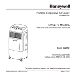
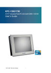
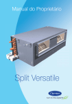
B1 - Engine/gearbox
check for leakage (from underneath)
Check that there is no leakage from the engine or gearbox. If there is leakage from the gearbox, the oil
l evel should be checked and the gearbox topped
up if necessary.
Oil quality (manual gearbox):
200, 700, 940/960
M 45146147: ATF-oil, type F or G.
M 90: Volvo P/N 11 61 423-7
400 (gearbox/final drive):
Volvo P/N 33 43 922-5.
850 (gearbox/final drive):
Volvo synthetic gearbox oil 11 61 423-7
Note! Always use new gaskets!
Note! On automatic gearboxes, oil level inspection
and topping up if necessary are carried out later in
the programme - D5 Automatic gearbox - top up oil.
B2 - Drain engine oil and replace oil filter
Drain engine oil
Remove the drain plug. Remove the drain plug.
Replace the washer.
Refit the drain plug and tighten.
Tightening torque
400:
22 N m
740/940: 65 N m
960:
40 N m
800:
35 N m
Replace the oil filter
Remove the filter with the filter removal tool 999 2903
(850: Use tool 999 5458 for removal of the oil filter).
I nsert the new filter and hand-tighten.
(see the instructions on the filter).
B3 - Automatic gearbox
drain the oil
(Topping-up; see D5)
AW 50-42 (850) and AW 30-43 (960): Oil change every 75,000 km only for cars in taxi traffic
and cars which spend a large proportion of their
operational life towing trailers/caravans.
400: Remove the drain plug in the oil sump. On the
ZF, also the plug in the differential housing.
Drain the oil.
Refit the drain plugs.
Always use new gaskets.
Tightening torque: ZF
15 Nm
CVT 30 Nm
AW 70/71/72, ZF 4 HP 22: Remove the drain plug
and drain the oil. Refit the drain plug.
Warning!
The oil may be very hot if the car has been driven
recently.
Refit and tighten the plugs. Tightening torque 15 Nm.
Always use new gaskets.
B4 - Clutch
check/adjust
Check/adjust the clutch play
Press the fork rearwards.
Play 1-3 mm. Adjust at the release fork.
B5 - Driveshafts
check play/wear
Check that there is no abnormal wear in the CV joints.
B6 - Driveshafts
check the rubber bellows
Check that the rubber bellows seal completely and
that they are undamaged.
B7 - Tyres
check
Check:
• tread depth
• wear pattern (indication of imbalance, faulty camber,
toe-in or wrong inflation pressure)
• that the type of tyre is the same on both wheels (Radial-cross-ply)
For studded tyres, check that all the tyres are studded.
1. Tyre inflation pressure too low
2. Tyre inflation pressure too high
3. Wrong toe-in
4. Imbalance
B8 - Brake linings
check
(Always check both the front and rear brake linings!)
Front brake linings
Use a mirror
I f the lining thickness is close to these values, the
workshop should recommend that they are replaced
soon.
Check that there is no leakage at the brake caliper or
connections.
If there is any uncertainty about lining thickness, the
wheels must be removed.
Place an extended slide gauge between points A and
B. The distance should not exceed 35 mm with brake
discs of normal wear.
Check that there is no leakage at the brake caliper or
connections.
Place an extended slide gauge between A and B.
The distance should not exceed 35 mm with brake
discs of normal wear.
Check that there is no leakage at the brake caliper or
connections.
Rear brake linings
With rear disc brakes
Minimum lining thickness: 2 mm
I f lining thickness is close to this value, the owner
should be advised to replace the linings soon.
Check that there is no leakage at the brake caliper or
connections.
Min. lining thickness: 2 mm
I f lining thickness is close to this value, the owner
should be advised to replace the linings soon.
Check that there is no leakage at the brake caliper or
connections.
Place a slide gauge between point C and the protective plate plane between the attachment lugs of the bearing housing and caliper holder.
Maximum permitted dimension with brake discs of
normal wear: 25 mm.
For replacement of brake linings:
Check the brake disc thickness
Measure the brake disc thickness. The value is not to
be less than the minimum specified in the table.
Min. thickness A-B (mm)
Front, solid disc
Front, ventilated disc
Rear
200, 700, 9401960
11.0
20.0
8.4
400
10.35
19.3
7.5
800
23.0
8.4
B9 - Brake hoses
check leakage/damage
Check that the brake hoses
- do not leak
- are firmly attached at their anchorage points
- are not chafed
- are not in contact with sharp corners or other surfaces
which can cause chafing or wear
- that there is no abnormal leakage from the shock absorbers
B10 - Brake and fuel lines
check leakage/damage
Check
- for leakage
- that all the brake and fuel lines are correctly clamped
and are undamaged
- that the pipes are not in contact with any sharp edges
- the handbrake wires and attachments
B11 - Fuel filter
replace
240, 700, 9401960: The fuel filter is located on a
bracket beside the fuel pump under the car. Note! On
the 240 with the B 230 E engine, it is located in the
engine compartment.
400 injection engines: The fuel filter is located to
the right of the fuel tank.
Connect the puncturing tool and fluid suction
pump
Undo the filter from the bracket. Clean the connections. Connect puncturing tool 999 5413. Connect the
hose from the puncturing tool to the fuel suction unit
(981 2270, 2273 and 2282). This method is described in detail in service bulletin 2-23-713.
Drain the fuel.
I nsert a new fuel filter.
The direction of flow is marked with an arrow on the
fuel filter.
Empty the fuel system
Remove:
- the cover above the throttle control pulley
- the cover over the fuel distribution pipe
- the cover for the valve on the fuel distribution pipe.
Connect tool 999 5484 hose/nipple to the fuel suction
unit 981 2270, 2273 and 2282. Start the suction
pump.
Connect the nipple from the suction pump to the valve on the distribution pipe.
Raise the car.
Remove:
- the cover above the fuel filter (previous version)
- the cover for the valve beside the fuel filter
Connect tool 999 5480 nipple to the valve ahead of
the fuel filter.
Drainage of the system takes about 2 minutes.
Reinstall the equipment in the reverse order.
I mportant!
Do not forget to refit the covers above the valves.
Replace the fuel filter
Undo the quick-release couplings from the fuel filter
with the help of a 17 mm wrench by pushing the slee
vestohra.
Undo the screw which retains the clamp around the
filter.
Replace the filter.
Refit in reverse order.
B12 - Fuel filter
drain water
Drain water
Undo the bleeder screw (1) a few turns.
Undo the drain screw (2). Tighten the screw when clean fuel comes through.
Tighten the bleeder screw.
Drain the water
Place a container below the filter. Connect a hose to
the drain screw (1) and let it hang down into the container.
Open the bleeder screw (3) on the fuel pump.
Undo the bleeder screw (1) and tighten it again when
clean fuel comes through.
Bleed the system
Move the hose to the air screw (3) on the fuel pump.
Use the filter's manual pump to pump fuel until clean
fuel comes through the air screw.
Shut the air screw and remove the hose.
Pump a few more times until a slight resistance is felt.
Start the engine and check that there is no leakage.
B13 - Fuel filter
replace
Replace the fuel filter
Use tool 2903
For fitting: Apply diesel oil to the rubber seal. Tighten
by hand until the seal is properly in place. Tighten additionally one 1/4 turn.
Start the engine and check for leakage.
Replace the fuel filter
Drain the fuel as per B 12.
Tighten the drain plug and remove the hose.
Undo the centre screw and remove the filter housing
and its insert. Remove the insert. Clean the components.
Lubricate the 0-rings with diesel oil
( Note! always use new 0-rings).
Fit all the 0-rings.
Place the new insert in the filter housing and tighten
the housing with the help of the centre screw.
Torque: 10 Nm.
Bleed the system as per B 12.
B14 - Final drive
Check for leakage - oil level
Check that there is no leakage from the final drive. If
there is any leakage, the oil level must be checked
and the final drive topped up if necessary.
Top up with oil quality API-GL-5 (MIL-L-2105 B or C),
rec.: Volvo's final drive oil, P/N 11 61 329-6 (0.5 litres).
Note! Fit a new seal.
B15 - Exhaust system
check
Check from underneath
• Leakage
• Attachment
• Condition