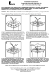
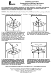
1
Service Manual
DS 200
DS 300
DS 400
DS 600
Freestanding and built-in absorption refrigerators
Pub. Nr.: 599363981 --- REV:A
Table of Contents:
1.
1.1.
1.2.
1.3.
2.
2.1.
2.2.
2.2.1.
2.2.2.
2.2.3.
2.2.4.
2.2.5.
2.3.
2.3.1.
2.3.1.1
2.3.1.2
2.3.1.3
2.3.2.
2.3.2.1
2.3.2.1.1
2.3.2.1.2
2.3.2.2
2.3.2.2.1
2.3.2.2.2
2.3.2.2.3
2.4.
2.4.1.
2.5
The appliance .............................................................................. 3
Specifications............................................................................... 3
Warning! ...................................................................................... 3
Spare parts, electrical wiring diagram .......................................... 3
Installation and repair operations................................................. 4
Tools ............................................................................................ 4
Cabinet, door ............................................................................... 5
Adjusting right and left-hand swing door ...................................... 5
Replacing lock ........................................................................... ..8
Replacing door panel ................................................................. ..9
Mounting the wheels .................................................................. 10
Mounting and dismountig the handle ......................................... 10
Electrical component.................................................................. 12
Operation ................................................................................... 12
Specifications............................................................................. 12
Self-test...................................................................................... 12
Defrosting .................................................................................. 12
Installation.................................................................................. 13
Replacing the elements under the light cover ............................ 13
Replacing potentiometer ............................................................ 13
Replacing built-in optical sensor ................................................ 14
Testing and replacing elements connected to Fuzzy III control.. 15
Testing assambled thermal fuse ................................................ 16
Replacing temperature sensor................................................... 16
Replacing heating element ........................................................ 17
Cooling aggregate ..................................................................... 21
Replacing cooling aggregate ..................................................... 21
Information................................................................................. 24
2
1. The appliance
1.1. Specifications
The appliance is available as a 20, 30, 40 or 60-litre refrigerator, freestanding or
built-in version, and operating with a wet absorption cooling system.
At ambient temperatures between +10°C and +32°C, the cooling unit
temperature can be adjusted between 0°C and +6°C using the thermostat.
The appliance is fitted with integrated electronic controls, which includes
regulating the interior temperature, automatic defrosting and light controls as
well.
1.2. Warning!
-
Do not repair or clean the appliance with the power supply cord
plugged in!
The appliance may only be operated by adults!
All instructions in the operating manual must be followed when
operating the appliance!
Any repair or service of the appliance that involves disassembling
electrical parts may be carried out by authorized service technicians
only!
Certain parts of the aggregate remain hot for a while after shutdown;
service must be carried out with caution!
After any repair that involves disrupting the electrical circuit or the
replacement of aggregate, an electrical insulation resistance test must
be carried out at all times! (see 2.3.2.2)
Only appliances with compliance qualifications may be connected to
the mains!
It is recommended to wear protective gloves for operations with
possible hand injuries!
In order to avoid damage to the appliance, the cabinet must be placed
on a soft padding (felt, sponge)
1.3. Spare parts, electrical wiring diagram
The lists of spare parts and electrical wiring diagrams by Product numbers can
be found on the web page
http://www.electrolux-ti.com.
Attention!
Any parts that need to be replaced during repair may only be replaced by parts
identical to the originals and which were chosen based on the list of spare parts!
Using parts other than original DOMETIC parts will result in lost warranty.
3
2. Installation and repair operations
2.1. Tools
Figure 1
Recommended tools:
- Universal pliers 160-mm, 2 pc.
- Magnetic screwdriver handle
- Pz 1 fitting-strip
- Pz 2 fitting-strip
- Phillips screwdriver Ph 1
- Standard screwdriver 120 * 5
- Standard screwdriver 100 * 4
- 14-mm wrench
- 1000-V electrical insulation resistance meter
- Electrical break-detecting device
4
2.2. Cabinet, door
2.2.1. Adjusting right and left-hand swing door
-
Remove bottle-holder bar from the inside door panel (Fig. 2)
Figure 2
-
Lay refrigerator on its aggregate unit side
Loosen up foot-frame’s screws (7 pc), remove foot-frame. (Fig. 3, 4, 5, 6)
Figure 3
-
Figure 4
Figure 5
Figure 6
Place refrigerator in upright position on workbench, open cabinet door to 180
degrees
Snap out the fixing tab of the upper hinge pin by the help of a screwdriver and
push out the pin, carefully, so that the door does not fall off. (Fig. 7,8)
Figure 7
Figure 8
5
-
Lift off door from bottom hinge pin, remove hinge washer (Fig. 9)
Figure 9
-
Remove bottom hinge pin and lower and upper hinge plug in the same way
as in case of the upper hinge pin
Install bottom hinge pin on opposite side, snap in place. (Fig. 10)
Figure 10
-
Pull spacer on bottom hinge pin, then place door on hinge pin. (Fig. 11, 12)
Figure 11
Figure 12
6
-
Snap in upper hinge pin lower and upper hinge plug. (Fig. 13)
Figure 13
-
Lay refrigerator on aggregate unit casing
Lead feed cable through foot-frame. (Fig. 14)
Figure 14
-
Attach grooves of foot-frame and aggregate unit casing, position foot-frame,
secure with 7 screws. (Fig. 15, 16)
Figure 15
-
Figure 16
Place refrigerator in upright position, make sure of unhindered operation of
the door and complete sealing.
7
2.2.2. Replacing lock
-
Open refrigerator door
Pull key from the lock, remove lock cover from rosette using 2 standard
screwdrivers. (Fig. 17)
Figure 17
-
Remove mounting screws from forehead panel, remove forehead panel by
slightly pulling.( Fig. 18, 19)
Figure 19
Figure 18
-
Remove locking plugs from bores of lock mounting screw. (Fig. 20)
Loosen and remove lock mounting screws. (Fig. 21)
Figure 20
Figure 21
8
-
Lift out lock. (Fig. 22)
Detach lock mounting plate from rosette using 2 standard screwdrivers, place
on new lock. (Fig. 23)
Figure 22
-
Figure 23
Reassembly is done in reverse order
Test locking - opening, adjust locking plate as necessary. (Fig. 24)
Figure 24
2.2.3. Replacing door panel
-
Remove mounting screw of forehead panel and lock cover. (see 2.2.2.)
Slightly pull forehead panel, remove
Pull out door panel from groove of doorframe, facilitating the pull by slightly
bending the door panel
Figure 25
-
Insert new door panel (max. panel thickness 2 mm) into door, push in place.
(Fig. 25)
Reinsert forehead panel, secure with screws
Push lock cover in place.
9
2.2.4. Mounting the wheels
Wheels, as options are available, which are packed into the inside of the cabinet.
The fastening screws (12 pcs of 3,5 φ x 22 drilling and tapping screw and 4 pcs
of φ 4 x 17 tapping screw for thermoplastic) are parts of this package as well.
The bores, to the wheels should be aligned, are injection moulded on the footframe.
Mounting:
-
Lay refrigerator on its top
Front wheels: Attach mounting plate of wheels on the side of the foot-frame
with bores, secure into the cabinet with 4 drilling and tapping screws (Fig. 26)
Back wheels: Attach mounting plate of wheels on the side of the foot-frame
with bores, secure with 2 drilling and tapping screws on the front, 2 of tapping
screw for thermoplastic on the back (Fig. 27)
Figure 26
-
Figure 27
Place refrigerator in upright position. Check the spinning of the wheels and
their turning ability.
2.2.5. Mounting and dismounting the handle
Handle as option is available. How to mount and dismount the handle:
Mounting:
-
Pick the handle hole cover from the forehead panel. Take care not to damage
the part. (Fig. 28, 29)
Figure 28
Figure 29
10
-
Lay the arched surface of the handle to the door frame. (Fig. 30)
Figure 30
-
Figure 31
Figure 32
Place the locating pin of the handle into the groove of the forehead panel.
(Fig. 31)
Join the tongue and the locating slot and by pressing the nib and the front
surface of the handle mate them together. (Fig. 32, 33)
Dismounting:
-
Figure 33
Press the nib and get off the handle slightly. (Fig. 34)
By rotating unhook the handle from the door frame. (Fig. 35)
Figure 34
Figure 35
11
2.3. Electrical component
2.3.1. Operation
2.3.1.1. Specifications
The appliance is fitted with integrated electronic controls (Fuzzy Logic III).
The electronics include the regulation of the interior temperature, the automatic
defrosting, as well as the control of the lighting. The light is 2 LED light sources,
which lights up the interior and also indicates the result of the self-test by the
electronics upon plugging in the appliance.
The switching of the light is controlled by an infrared optical sensor operated by
the door.
The temperature regulation of the cooling unit can be done by the potentiometer
fitted in the light cover.
A thermal fuse is also fitted in the electrical circuit to prevent the aggregate from
overheating, which, after it’s been turned off once, will not turn back on.
2.3.1.2. Self-test
When plugging in the appliance, the built-in electronics performs a self-test.
The system checks the status of the peripheries. The result is indicated by the
varying number of flashes of the illuminating LED’s (0.5Hz). The evaluation is
contained in the table below.
Number of flashes
N=0
N=1
N=2
N=3
Error status
General error
All OK controlling potentiometer is not detected
All OK controlling potentiometer detected
NTC sensor error (cooling unit sensor)
After three flashes the LED’s keep flashing continuously at a higher frequency.
If no error is detected by the electronics (two flashes) then, after two seconds it
turns on the feed voltage for the heating element, and the normal, regulated
operation begins.
2.3.1.3. Defrosting
Defrosting is carried out automatically by the controls, as follows:
-
It turns off 37 hours after first switching on, defrosting for 2 hours, then turns
back on.
Afterwards, in every cycle after 22 operating hours a 2-hours defrosting
period follows.
12
2.3.2. Installation:
The electrical component of the appliance is divided between two major
connection points:
1. The lighting panel under the light cover
2. The Fuzzy III control panel under the electric cover
2.3.2.1. Replacing the elements under the light cover
-
Unscrew cover mounting screw.( Fig. 36)
Snap out the light cover by slightly pulling it forward.( Fig. 37)
Snap out lighting panel by pushing the locking tab aside.( Fig. 38, 39)
Figure 36
Figure 38
-
Figure 37
Figure 39
When replacing the panel, pull off the PCB (printed circuit board) connections
from the faulty panel, push back on the new panel to the same position
(according to wiring diagram).
2.3.2.1.1. Replacing potentiometer
-
Push down the thermostat button with a screwdriver. (Fig. 40)
Loosen up retaining nut. (Fig. 41)
Pull off PCB connection of the potentiometer from the lighting panel,
remove potentiometer.
13
Figure 40
-
Figure 41
Insert new potentiometer so that its outlet faces the connection point,
tighten restraining nut
Push up PCB connection
Push up thermostat button, paying attention that the potentiometer’s shaft
jointing fits with its positioning to the thermostat button.
Check that the potentiometer can be turned.
2.3.2.1.2. Replacing built-in optical sensor
-
Pull off PCB connection from lighting panel
Slightly pressing with fingertips the button-head ends of the sensor
elements, push out the sensor from its casing, hold it by its wire end,
remove (Fig. 42)
Insert new sensor in the casing, push in place with fingernails. (Fig. 43)
Figure 42
-
Figure 43
Push PCB connection onto panel
14
-
Upon finishing the actions, snap lighting panel back into its casing, adjust
wires
Insert light cover in groove of inner chamber, snap in. (Fig. 44)
Screw back mounting screw of lighting cover. (Fig. 45)
Figure 44
Figure 45
Testing of electrical insulation resistance is not necessary after disrupting this
electrical part.
After finishing the installation, connect the appliance to the mains, and check its
operation based on the self-test by the electronics. (see 2.3.1.2.)
2.3.2.2. Testing and replacing elements connected to Fuzzy III control
These elements become accessible as follows:
-
Lay refrigerator on door
Unscrew restraining screws from aggregate unit casing, remove aggregate
unit casing. (Fig. 46, 47, 48)
Figure 46
Figure 47
15
Figure 48
-
Unscrew screws from electrical cover, remove cover
Slightly pressing the locking tab, lift out Fuzzy III printed circuit board from the
base board. (Fig. 49, 50)
Figure 49
-
Figure 50
After finishing the actions, re-assembly is carried out in reverse order, paying
attention to the positioning of the wires and to the fitting of the aggregate unit
cover and the foot-frame
In each case after disrupting the electrical circuit, test electrical insulation
resistance (with a 1000-V electrical insulation resistance meter.)
The insulation resistance is RSZIG > 2Mohm
2.3.2.2.1. Testing assembled thermal fuse
The thermal fuse starts functioning in the event of the aggregates overheating, by
disrupting the electrical circuit of heating. It does not turn back on automatically,
in case of its break the appliance can be repaired by replacing the aggregate
(see 2.4.1), a component of which being the faultless thermal fuse fitted on the
boiler.
In the event of suspecting this error, the thermal fuse can be tested with a breakdetecting device, as follows:
-
Disconnect the ends of the thermal fuse wire from the Fuzzy III PCB board
and from the heating element wires
Connect break-detecting device on the free wire ends, test connection
On the device, the faulty thermal fuse indicates a break, the faultless
indicates short circuit. Decide on the further procedure of repair depending on
the result of the test.
2.3.2.2.2. Replacing temperature sensor
-
Pull off PCB connection of temperature sensor from the Fuzzy III panel
Place refrigerator in upright position, open door
16
-
Snap out plugs from temperature sensor cover, unscrew restraining screw
(Fig. 51, 52, 53)
Figure 51
-
Figure 52
Figure 53
Lift off sensor cover, lead out sensor
Pull out sensor from cabinet towards back panel
Thread new sensor back in the cabinet, place sensor tip in cover casing
Wind sensor wire cover at 100 mm length onto the locking tabs
Reinsert cover into its casing, secure with screw
Reinsert plug
On the back panel, push sensor connection back to Fuzzy III panel, snap
panel back in
Reinstall electrical cover, aggregate unit casing (Fig. 54)
Figure 54
-
Place refrigerator in upright position
Test electrical insulation resistance (with a 1000-V electrical insulation
resistance meter.)
The insulation resistance is RSZIG > 2Mohm
If results are satisfactory, connect to the mains; check its operation based on
the self-test by the electronics
2.3.2.2.3. Replacing heating element
-
Lay refrigerator on door
Remove aggregate unit casing, foot-frame, electrical cover
2.2.1.)
Disconnect themal fuse from heating element
17
(see 2.3.2.2.,
-
Bend out cover locking tabs of boiler-insulation. (Fig. 55, 56)
Remove upper-lower boiler cover. (Fig. 57, 58)
Figure 55
Figure 56
Figure 58
Figure 57
-
Turn insulation, detach rims apart by slightly pressing the casing
Turn out boiler insulation together with casing from under the boiler (Fig. 59,
60)
Figure 59
Figure 60
18
-
Mark mounting position of heating element on the boiler with a permanent
marker (to help reinstallation) (Fig. 61)
Push down wire clamp of heating element. (Fig. 62)
Figure 61
-
Turn heating element toward back panel. (Fig. 63)
Push down clamp of heating element using 2 universal pliers. (Fig. 64)
Figure 63
-
Figure 62
Figure 64
Pull up clamp to about halfway on new heating element (45 mm from upper
edge)
Fit upper edge of heating element to the marking that indicates the positioning
With a firm press on the clamp, push heating element onto the boiler (Fig. 65)
Figure 65
19
-
Position element, adjust its seating (in all types, the upper edge of the
element has to be 13 mm from the mid-section of the boiler’s lowest
indention)
Turn element so that it faces the opposite way from the intake tube. (Fig. 66)
Figure 66
-
Reinsert boiler insulation, snap together, turn into position.
Reinsert boiler covers, secure by bending in the casing tabs. (Fig. 67, 68, 69)
Figure 67
-
Figure 68
Figure 69
Thread the wire clamp of heating element onto the element wire, snap clamp
onto the fluid heat-exchange pipe (Fig. 70)
Figure 70
20
-
Push together the electrical connection of the heating element wire and the
thermal fuse wire, adjust wires
Reinsert electrical cover, foot-frame, aggregate unit casing, secure with
screws (see 2.3.2.2., 2.2.1.)
Place refrigerator in upright position
Test electrical insulation resistance (with a 1000-V electrical insulation
resistance meter.)
The insulation resistance is RSZIG > 2Mohm
2.4. Cooling aggregate
2.4.1. Replacing cooling aggregate
-
Open refrigerator door
Unscrew 4 screws of cooling flange. (Fig. 71)
Remove cooling flange. (Fig. 72)
Figure 72
Figure 71
-
Turn refrigerator onto door
Remove aggregate unit casing, foot-frame, electrical cover (see 2.3.2.2.,
2.2.1.)
Lift out Fuzzy III panel from its casing by pressing on the locking tab
Pull down PCB connection of thermal fuse from the Fuzzy III panel
Pull apart thermal fuse – heating element electrical connection
Remove heating element according to 2.3.2.2.3
21
-
Unscrew mounting screws of aggregate, lift out faulty aggregate, set aside.
(Fig. 73, 74)
Figure 73
-
Figure 74
Insert new aggregate into cabinet. The replacement aggregate has the
thermal fuse built-in.
Check correct positioning of the thermal fuse. The distance between lower
edge of temperature controller’s mounting spring and mid-section of the top
indention of boiler is based on (X). (Fig. 75)
Figure 75
Its value is:
Type
DS 200
DS 300
DS 400
DS 600
Value to be measured (mm)
X = 35.5
X = 16.5
X = 16.5
X = 36.5
In case of discrepancies the positioning has to be corrected.
22
-
Place drain water evaporator onto fluid heat-exchange pipe, making sure that
the end of the drain water outlet pipe reaches in the drain water evaporator.
(Fig. 76, 77)
Figure 76
-
Figure 77
Secure aggregate with screws.
Install heating element, boiler insulation, according to 2.3.2.2.3
Push together thermal fuse – heating element electrical connection
Push PCB connection of thermal fuse onto Fuzzy III panel
Snap Fuzzy III panel back into base board, making sure that the positioning
pin of the base board fits into the bore of the panel (Fig. 78)
Figure 78
-
Reinsert electrical cover, foot-frame, aggregate unit casing, secure with
screws (see 2.3.2.2., 2.2.1.)
Place refrigerator in upright position
23
-
Reinsert cooling flange, secure with 4 screws, only the original corrosionproof screws or screws of identical quality may be used (Fig. 79, 80)
Figure 79
-
Figure 80
Test electrical insulation resistance (with a 1000-V electrical insulation
resistance meter.)
The insulation resistance is RSZIG > 2Mohm
2.5 Information :
Certain devices do not include all of the elements (lock, aggregate unit casing).
Parts of the instructions describing this do not apply to such devices.
Jászberény, 04.06.2004
Compiled by:
Rev. : A
24
László Kaszab
Technologist engineer