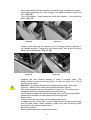
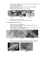
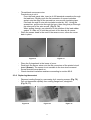
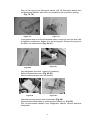
1
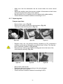
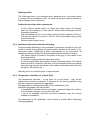
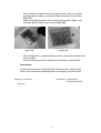
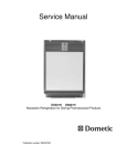
Service Manual
MF 20-60 60-litre refrigerator with freezer compartment
Models :
A552,
A552E
A552EM
A552ESZ
Pub. Nr.: 599363886 --- REV.:A
EA0600
EA0601
EA0602
EA3200
WA3200
RH057 D3
RH060
RH060 D
RH060 D2
RH060 DF
Table of Contents:
1.
1.1.
1.2.
1.3.
2.
2.1.
2.2.
2.2.1.
2.2.2.
2.2.3.
2.2.4.
2.2.5.
2.2.6.
2.3.
2.3.1.
2.3.2.
2.3.3.
2.3.4.
2.3.5.
2.3.6.
2.3.7.
2.3.8.
2.3.9.
2.4.
2.4.1.
The appliance .................................................................................... 3
Specifications .................................................................................... 3
Important notes.................................................................................. 3
Spare parts, electrical wiring diagram................................................ 3
Installation and repair operations....................................................... 4
Tools.................................................................................................. 4
Cabinet, door ..................................................................................... 5
Adjusting right and left-hand swing door............................................ 5
Replacing legs ...................................................................................6
Replacing cowl ..................................................................................7
Replacing lock ...................................................................................7
Replacing door panel.........................................................................8
Replacing freezer door ......................................................................9
Electrical components......................................................................10
Replacing lighting device and bulb ..................................................10
Replacing bulb without dismounting lighting device.........................12
Replacing heating element (Cylindrical heating element) ................13
Replacing heating element [”Half-moon” heating element (as of May 2003)]15
Replacing temperature sensor.........................................................16
Replacing thermostat.......................................................................17
Replacing timer................................................................................20
Appliance with semi-automatic defrosting........................................21
Temperature controller ....................................................................21
Cooling aggregate ...........................................................................22
Replacing cooling aggregate ...........................................................22
2
1. The appliance
1.1. Specifications
The appliance is a 60-litre upright refrigerator, operating with a wet absorption cooling
system.
At ambient temperatures between +16°C and +32°C, the cooling compartment
temperature can be adjusted between 0°C and +6°C using the thermostat. The
minimum temperature of the freezer compartment is - 12°C.
You can make ice cubes using the ice tray placed in the freezer compartment.
Defrosting of the appliance is either automatic, where the appliance is switched off for
1,5 to 2 hours every 24 hour by the installed control, or it is semi-automatic and can
be initiated by pressing the defrost switch. Restart is done automatically in both
cases.
1.2. Important Notes
-
Do not repair or clean the appliance with the power supply cord plugged in!
The appliance may only be operated by adults!
All instructions in the operating manual must be followed when operating
the appliance!
Any repair or service of the appliance that involves disassembling electrical
parts may be carried out by authorized service technicians only!
Certain parts of the aggregate remain hot for a while after shutdown;
service must be carried out with caution!
After any repair that involves disrupting the electrical circuit or the
replacement of aggregate, an electrical insulation resistance test must be
carried out at all times! (see 2.3.3.)
Only appliances with compliance qualifications may be connected to the
mains!
It is recommended to wear protective gloves for operations with possible
hand injuries!
1.3. Spare parts, electrical wiring diagram
The lists of spare parts and electrical wiring diagrams by Product numbers can be
found on the web page http://www.electrolux-ti.com.
Attention!
Any functional parts that need to be replaced during repair may only be
replaced by parts identical to the originals and which were chosen based
on the list of spare parts!
3
2. Installation and repair operations
2.1. Tools
Figure 1
Recommended tools:
- Universal pliers 160-mm, 2 pc.
- magnetic screwdriver handle
- Pz 1 fitting-strip
- Pz 2 fitting-strip
- Phillips screwdriver Ph 1
- Standard screwdriver 120 * 5
- Standard screwdriver 100 * 4
- 14-mm wrench
- Electric hand drill whit φ 3,2 mm drill
4
2.2. Cabinet, door
2.2.1. Adjusting right and left-hand swing door
-
Unscrew top door mount screws. (Fig. 2)
Unscrew door mount hole cover screws. (Fig. 3)
Open door.
Pull top door mount by tilting door. (Fig. 4)
Figure 2
-
Figure 3
Set aside door mount, unhinge door from bottom door mount pin.
Pull door mount hole cover. Help with standard screwdriver when pulling.
Place cabinet on its back carefully so that the hinge is not damaged.
Install bottom door mount on opposite side. (Fig. 5, 6)
Figure 5
-
Figure 4
Figure 6
Unscrew door mount pin from top door mount, then screw from opposite
direction and tighten. (Fig. 7, 8, 9)
Figure 7
Figure 8
5
Figure 9
-
Stand cabinet on its legs.
Place door on bottom door mount.
Place the replaced top door mount pin into top door mount bore of door,
then push door mount into left-hand-side opening of cabinet and secure
with 2 screws. (Fig. 10)
Figure 10
Figure 11
-
Push door mount hole cover into upper right-hand-side opening, then
secure with a screw. (Fig. 11)
Make sure of unhindered opening and appropriate secure sealing of the door.
If needed, make corrections after loosening the screws that secure the door.
Re-fasten the screws.
- When only replacing the door, dismounting of the door mount hole cover
and door stop or the switching of the door mounts is not necessary.
2.2.2. Replacing legs
-
Place unit on its back carefully so that the hinge is not damaged.
Dismount outer legs by unscrewing 2-2 screws. (Fig. 12)
Take out inner legs from outer legs. (Fig. 13)
Mount inner legs by securing them using bores further apart from each
other. (Fig. 14)
Figure 12
-
Figure 13
Figure 14
Screw remaining screws into appropriate bores, fasten.
Set aside the outer legs (possible re-mounting).
Place the refrigerator on its legs.
6
2.2.3. Replacing cowl
-
Turn cabinet onto door using appropriate protection support.
In case of curved door use support on both sides to avoid oscillation
(cardboard support).
Unscrew the screw that secures cowl, while keeping the end of cowl from
folding down. (Fig. 15, 16)
Lastly, remove screw next to boiler insulation.
(mounting ease) (Fig. 17)
Figure 15
-
Figure 16
Figure 17
Lift up cowl, then put replacement part in place.
Fasten screws starting with the screw next to boiler insulation, while
holding the unfastened end of cowl with your hand.
Tighten screws. While fastening, check the leveling of cowl and plate.
Adjust as necessary.
2.2.4. Replacing lock
”Snap lock” model
-
Open door.
Pull down rosette using 2 standard screwdrivers. (Fig. 18)
Pop up lock cover:
With the bolt in locked position, pull the rim of lock cover onto the bolt
using a standard screwdriver to keep it from snapping back. (Fig. 19)
Snap off lock cover lid using 2 standard screwdrivers. (Fig. 20)
Figure 18
Figure 19
7
Figure 20
-
Unscrew securing screws. (Fig. 21)
Pull out lock. (Fig. 22)
Figure 21
-
Figure 22
Reassembly is done in reverse order.
Rosette and lock cover lid should be snapped in place applying slight
pressure.
When popping the lock cover lid open, the bolt must be in locked position.
”Turn lock” model
-
Open door.
Pull down rosette using 2 standard screwdrivers.
Unscrew securing screws.
Pull out lock toward door lining.
Push new lock in lock bore of door.
Reinsert and tighten securing screws.
Push rosette in place applying slight pressure.
2.2.5. Replacing door panel
-
Replacement of the door panel should be done with the door detached and
the lock dismounted.
Remove door shelves. They can be removed by lifting the shelves.
Place door – with door lining down – on protective support.
Unscrew screws that secure locking-panel. (Fig. 23)
Lift locking-panel from its nest. (Fig. 24)
Pull out door panel. (Fig. 25)
Figure 23
Figure 24
8
Figure 25
-
Adjust foil lining.
Place the the door panel up to the handle lath into groove on one side of
door.
Slightly bend door panel. (Fig. 26)
Snap door panel into place in groove on other side of door.
Push door panel until cylindrical bores on the plate and on the door are
concentric. (Fig. 27)
Figure 26
-
Figure 27
Insert locking-panel, secure with screws.
Reinstall lock.
Reinstall door.
2.2.6. Replacing freezer door
-
Open refrigerator door.
While the freezer door is shut, insert a standard 4*100 screwdriver
between the freezer’s top door mount and the freezer door, with slight
pressure lift the top door mount pin out from its bore. (Fig. 28)
Tilt and remove the freezer door by a quick pull on the upper edge of the
freezer door. (Fig. 29)
Lift out the freezer door from the bottom door mount bore, then remove the
bottom hinge pin from the freezer door bore. (Fig. 30)
Figure 28
-
Figure 29
Figure 30
Insert the hinge pin into the bottom bore of the new freezer door. (Fig. 31)
Insert the freezer door with the pin into the freezer’s door mount bore so
that the bolt secures the freezer door. (Fig. 32)
Inserting a standard 4*100 screwdriver between the freezer door and the
upper freezer door mount, bend the freezer door mount upwards.
Applying slight pressure on the upper part of the freezer door, snap the top
door mount pin in place. (Fig. 33)
9
Figure 31
2.3.
Figure 32
Figure 33
Check the unhindered operation and closing of the freezer door.
Electrical components
2.3.1. Replacing lighting device and bulb
-
Remove screws securing lighting device. (Fig. 34)
Detach blocking tab on reflector from the lighting device by pressing the
reflector plate. At the same time, push the light shield off of the casing.
(Fig. 35, 36)
Figure 34
-
Figure 35
Figure 36
Unscrew bulb. (Fig. 37)
Snap the lighting device open by detaching the tab behind the threaded
part of the casing with a screwdriver. (Fig. 38)
Figure 37
Figure 38
10
-
Disconnecting electrical wires, removing defective lighting device.
Reconnecting electrical wires in new casing. Prior to wiring, wires must be
threaded in the appropriate bore of the reflector holder. (Fig. 39)
Placement of the socket in the casing so that its securing rib fits in the
groove of casing. Screws securing the wires must stand outwards from
lighting device. (Fig. 40)
Figure 39
-
-
Insert control switch while holding socket in place with your finger. Screw in
bulb while constantly holding down the socket. (Fig. 41)
The bulb holds the socket elements in place, then the reflector mount can
be popped open. When snapping shut, the blocking tab should be slightly
pressed with a screwdriver. (Fig. 42, 43)
After snapping shut, fitting should be tested.
Figure 41
-
Figure 40
Figure 42
Figure 43
Replacing light shield. Make sure that the groove fits correctly on the light
shield.
While pushing aside the blocking tab of the reflector plate with a
screwdriver, the casing can be pushed in place. (Fig. 44)
11
-
Prior to installing the lighting device, the securing screws must be
reinserted into the lighting device so that the tips of the screws overhang
by 1-2 mm. These help positioning. (Fig. 45)
Install lighting device, with attention to the placement of electrical wires.
Figure 44
-
Figure 45
Tightening securing screws. Make sure it fits correctly. Then must be no
gap between the lighting device and the inner compartment.
2.3.2. Replacing bulb without dismounting the lighting device
-
By pushing the reflector plate unhinge blocking tab on reflector from the
light shield. At the same time, push the light shield off of the casing with a
screwdriver. (Fig. 46)
Unscrew defective bulb and replace with a new one; pay attention to
appropriate back-up power. Bulb needs to be tightened to an extent that
loose connection does not cause contact failure. (Fig. 47)
Replacing the light shield. Make sure the groove fits correctly on the light
shield. (Fig. 48)
The light shield can be slid in place by slightly pressing the blocking tab
with a screwdriver.
Figure 46
Figure 47
12
Figure 48
2.3.3. Replacing heating element (cylindrical heating element) :
-
Remove screws of electrical cover. (Fig. 49, 50)
Figure 49
-
Figure 50
Remove electrical cover.
Disconnect electrical wires of heating element. (Fig. 51, 52, 53)
Unscrew and remove the wire clamp. (Fig. 54)
Figure 51
Figure 52
Figure 53
Figure 54
13
-
Turn metal casing of boiler-insulation so that the joint rim becomes visible.
While slightly pressing the metal casing of the boiler-insulation, detach the
rims. (Fig. 55)
Turn out insulation – metal casing and rock wool together – from under the
boiler. (Fig. 56)
Figure 55
-
Figure 56
Loosen screw securing the element, pull out heating element upwards. If
the heating element is jammed in the heating tube, then push it out from
below with a screwdriver. (Fig. 57, 58)
Figure 57
Figure 58
-
Installing the new heating element is done in reverse order. The
heating element must be securely fixed. (It must not slide out at 100 N
axially tractive effort.)
- Attention ! The electrical power of a heating element with ”fuzzy logic”
control is different from those with electromechanical control!
- The boiler-insulation can be reinserted by turning it in. The rims must be
snapped together by slightly pressing the metal casing.
- Turn in boiler-insulation so that the securing bore is in the correct position.
- Attach boiler-insulation to back panel with securing screw.
- Adjust wires.
- Connect electrical connections at the appropriate points.
- In appliances with ”fuzzy logic” control, snap back the printed circuit board
into the base board. When replacing, make sure that the driving shaft
jointing fits in the potentiometer’s bore.
- Secure wire clamp.
- Reinsert electrical cover, secure with screws.
14
-
Place refrigerator in upright position. Check that the thermostat switch
turns freely in the entire control range.
Check electrical insulation resistance (with 1000-V electrical insulation
resistance metering device.)
The insulation resistance RINS > 2Mohm
2.3.4. Replacing heating element (”Half-moon” shaped, as of May 2003):
-
Unscrew hinge screw on boiler side, slightly bend out side wall of hinge.
(Fig. 59)
Remove temperature controller from boiler
Bend out tabs of boiler casing.
Lift off boiler’s cover. (Fig. 60, 61)
Figure 59
-
-
Figure 61
Remove boiler insulation.
Mark securing position of the heating element on the boiler to help
reassembly. (marker)
Push down clamp securing element wire. (Fig. 62)
Rotate back heater element in the direction of back panel. (Fig. 63)
Push down securing clamp of heater element using 2 universal pliers.
(Fig.64)
Figure 62
-
Figure 60
Figure 63
Figure 64
Replace the heating element. Electronically, this operation is identical to
those described for cylindrical element.
Attention! The electrical power of a heating element with ”fuzzy logic”
control is different from those with electromechanical control!
Positioning the heating element. Place securing clamp in the middle of the
element.
Place upper edge of heating element at the marking of position.
By applying firm pressure to the clamp, snap the heating element onto the
boiler.
15
-
Position element, adjust its position. The element must be positioned in the
direction of hinge. (Fig. 65)
Reinsert boiler-insulation, secure.
Reinsert boiler-insulation cover, bend back blocking tabs. (Fig. 66)
Reinsert temperature controller
Snap back wire clamp of heating element. (Fig. 67)
Figure 65
-
Figure 66
Figure 67
Reassemble loosened end of hinge
Check electrical insulation resistance according to 2.3.3.
2.3.5 Replacing temperature sensor
-
Remove electrical cover. (See 2.3.3)
Push off flat sockets of temperature sensor from the flat connectors of
printed circuit board. (Sensor)
Open refrigerator door, remove plugs from two bores of sensor cover in the
inner compartment, set aside. (Fig. 68)
Unscrew screws of sensor cover, lift out sensor from cover. (Fig. 69, 70)
Figure 68
-
Figure 69
Figure 70
Pull out sensor wire towards inner compartment carefully, so that the flat
sockets do not get jammed in the lead rubber gasket. (Fig. 71, 72)
Figure 71
Figure 72
16
-
-
Thread back new sensor wire.
Practical way to do it:
From the back panel side, insert a 4x100 standard screwdriver through
the lead bore. Slightly push the flat connector of sensor insulation
socket onto the edge of the screwdriver, secure with insulating tape.
Fold back the end of wire with insulation socket by 180°. Using the
screwdriver, pull the wire through the bore, then using that pull through
the other end of the wire as well. (Fig 73, 74)
When pulling through, pay attention to the position of the lead rubber
gasket. If it falls out, it must be put back in the bore by all means.
Place the sensor head in the nest of the sensor cover, screw the cover
back in place.
Figure 73
-
Figure 74
Place the 2 plugs back in the bores of cover.
Push back the sensor wires onto the flat connectors of the printed circuit
board (Sensor). The sensor is not sensible to the two wires reversed.
Screw electrical cover back on.
Check electrical insulation resistance according to section 2.3.3.
2.3.6 Replacing thermostat
-
Dismount cooling flange by unscrewing its 4 securing screws. (Fig. 75)
Pull out thermostat capillary from cooling flange bore, straighten.
(Fig. 76, 77)
Figure 75
Figure 76
17
Figure 77
-
Pop out wire plug from thermostat switch, pull off thermostat switch from
the thermostat switch’s axis with a universal plier with protective coating.
(Fig. 78, 79)
Figure 78
-
Figure 79
If the gasket slips off of the thermostat switch, remove it from the bore with
a magnetic screwdriver, detach it to the driving bolt. Reinsert the plug into
the bore, set aside switch. (Fig. 80, 81)
Figure 81
Figure 80
-
Lay refrigerator onto door, support if necessary.
Remove thermostat cover. (Fig. 82, 83)
Remove electrical wire from thermostat.
Figure 82
-
Figure 83
Unscrew securing screws from thermostat. (Fig. 84)
Dismount thermostat case by loosening the locking nut. (Fig. 85)
Pull out thermostat capillary from refrigerator cabinet, remove defective
thermostat.
18
-
Reinstall thermostat case onto the new thermostat, secure with nut. During
assembly make sure that the navigation-securing pin of thermostat fits into
the bore of plate. (Fig. 86)
Figure 84
-
Figure 85
Figure 86
Reinsert thermostat onto panel, secure with screws.
Reassemble thermostat wires.
Reinsert thermostat cover, secure.
Insert thermostat capillary into cabinet approx. 200 mm deep. (Fig. 87)
Figure 87
-
Place refrigerator in upright position.
Insert thermostat capillary into cooling flange approx. 200 mm deep.
Reinsert cooling flange, carefully positioning thermostat capillary, then
secure with 4 plate screws (the original corrosion-proof screws should be
used).
Push thermostat switch back onto the shaft of thermostat. When
positioning, make sure that the shaft jointing fits with the switch bore
jointing. (Fig. 88)
Figure 88
19
-
Make sure that the thermostat can be turned within the entire control
range.
Adjust the capillary spiral that remains outside of thermostat so that it does
not overhang from the outline of the cabinet.
Seal the point of exit of capillary from the cabinet with rubber sealing.
Check electrical insulation resistance according to 2.3.3.
2.3.7 Replacing timer
Paragon-type timer
-
Remove timer cover. (Fig. 89)
Remove wire clamp, push down electrical wire. (Fig. 90)
Unscrew screws securing timer. (Fig. 91)
Figure 89
-
Figure 91
Replace timer, set: turn defrost marking clockwise by 90º compared to
marking on the casing. Meanwhile, you should hear 2 clicks. This way the
timer is definitely turned on. (Fig. 92, 93)
Reinsert timer, making sure that the rotating part sits in the bore of the
textile-bakelite housing. (Fig. 94)
Figure 92
-
Figure 90
Figure 93
Figure 94
Secure timer with screws.
Push back electrical wires according to the wiring diagram.
Reinsert timer cover, secure.
Check electrical insulation resistance according to 2.3.3.
20
Diehl-type timer
The Diehl-type timer is not equipped with a separate cover, the control switch
is covered with a transparent cover. Its electrical wiring is exactly identical to
that of Paragon timer connection.
Setting the new timer after replacement:
-
On the 24-hour control switch, on which one notch means 15 minutes,
push out 6 pins radially (1,5 hour period). All the other switch pins must be
in pushed-in position.
The first pushed out pin on the control switch must be rotated to 0.00 hour.
This way the switch-on is set to 1.30 hour. The control switch may only be
rotated clockwise.
Reinsert control switch cover.
2.3.8 Appliance with semi-automatic defrosting
In some models defrosting is not controlled by automatic controls but the user
needs to initiate it by pressing the defrost switch located at the center of the
thermostat switch. Restarting is done automatically by the thermostat. Its
assembly is almost identical to electromechanical thermostats with timers.
- The defrost switch is located in the place of the plug, in the middle of the
thermostat switch.
- It is pulled of together with the thermostat switch.
- It can be reassembled after pushing up the thermostat switch. The defrost
switch should be inserted in the bore of the thermostat switch and should
be pushed up onto the defrost pin in the middle of the thermostat shaft with
an approx. Ø5 cylinder pin.
Naturally, there is no defrost timer in these devices.
2.3.9 Temperature controller (as of April 2002)
The temperature controller – in the event of a circuit break – may not be
replaced as a service component. If switched off, the cooling appliance may
only be repaired by replacing the aggregate.
The aggregate for servicing purposes is only available as a set.
Beside the aggregate, the set includes:
- 1 temperature controller with the necessary maximum length wire, without
the connection element on the ends of the wire.
- 1 set of all available electrical connection elements, also the screws
needed for installation.
The description of the application can be found in section 2.4.1 (Replacing
cooling aggregate).
21
2.4. Cooling aggregate
2.4.1. Replacing cooling aggregate
Attention! The cooling aggregate of refrigerators that are equipped
with a temerature controller (as of April 2002) must only be replaced
when also replacing the temperature controller or, in the event of a circuit
break in the temperature controller, the cooling aggregate must also be
replaced at all times.
In appliances with no temerature controller only the aggregate needs to be
replaced. The assembly instructions must be applied accordingly.
In case of electrical circuits of appliances with ”Fuzzy logic” and with
electromechanical thermostats the procedures should be followed
accordingly.
-
Open refrigerator door.
Unscrew 4 screws of cooling flange, remove cooling flange. (Fig. 95)
Open freezer door, unscrew 2 screws securing freezer. (Fig. 96)
Figure 95
-
Figure 96
Turn refrigerator onto its door, secure. (see: 2.3.3)
Disassemble heating element from boiler (see: 2.3.3, 2.3.4)
Remove electrical cover or thermostat cover.
Disconnect electrical wire of temperature controller.
Pull apart temperature controller – heating element connection.
Unscrew wire clamp. (See: 2.3.3)
Unscrew screws securing aggregate. (Fig. 97)
Pull off drain water evaporator from fluid heat-exchange pipe.
Figure 98
Figure 97
-
Lift out aggregate, set aside for workmanlike destruction. (Fig. 98)
22
Final assembly of temperature controller, mounting onto aggregate:
(This procedure is not necessary for appliances with no temperature controller)
Figure 99
Figure 99 presents the necessary elements and tools, for your information.
-
Cut the wire of the temperature controller to size, according to the size of the wire
of the temperature controller on the replaced aggregate. (Fig. 100)
From the connection kit, choose the connection elements that are identical to the
original temperature controllers.
Press connection elements with press tool. (Fig. 101)
Pull insulation sockets onto connectors. (Fig. 102)
Figure 100
Figure 101
Figure 102
23
-
Secure temperature controller on boiler-tube of aggregate with 2 screws.
Pull protecting socket onto the end of outer securing screw of temperature
controller, because the sharp end of screw can cause an accident.
(Fig. 103, 104)
Figure 103
Figure 104
Installation :
-
Reassemble aggregate and heating element in opposite order of
disassembly.
Reinsert electrical connections of temperature controller according to the
status prior to disassembly.
Screw wire clamp back on.
Reinsert electrical cover or thermostat cover, secure with screw.
Figure 105
-
Push drain water evaporator onto fluid heat-exchange pipe.
Make sure the drain water outlet pipe’s outlet portion reaches in the drain
water evaporator. (Fig. 105)
Lay refrigerator on its back.
Drill 2, 3.2mm diameter bores on the freezer mount (where the cooling
aggregate is attached to the freezer compartment) according to the
positioning of bores on the freezer compartment. (Fig. 106)
During this procedure, you must wear protective goggles !
Figure 106
24
-
Secure freezer compartment with 2 plate screws. Only the original
corrosion-proof screws or screws of identical quality may be used.
(Fig. 107)
Place cooling flange back, secure with 4 plate screws. Again, only
corrosion-proof screws may be used. (Fig. 108)
Figure 107
-
Figure 108
Place refrigerator in upright position, remove any metal shavings from
internal areas.
Check electrical insulation resistance according to section 2.3.3.
Information:
Certain devices do not include all of the elements (lock, lamp, hinge).
Parts of the instructions describing this do not apply to such devices.
Jászberény, 12/12/2003
Compiled by: László Kaszab
Technologist engineer
Rev. : A
25