1
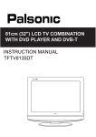
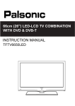
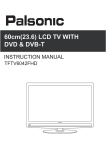
SK0-0055-001 HUMIDISTAT
INSTALLATION INSTRUCTIONS
The humidistat is designed for either return air duct or wall
mounting. Packaged in a duct mount configuration, (For this type
mounting begin installation at the section labeled return air duct
installation on page 2.) for conversion to a wall mount configuration
simply pull off the knob and remove the mounting screws and rotate the
control 180° and reattach the mounting base, (For this type mounting
begin installation at the section labeled wall mount installation on
page 3.).
DANGER
∗ Do not cut or drill any air-conditioning or electrical
accessories during installation.
∗ Fatal electrocution is possible if you contact a live wire.
∗ Electrical power can cause electrical shock
∗ Disconnect all electrical power supplied to the equipment
before beginning installation.
∗ Blindness can occur if freon contacts your eyes.
CAUTION
∗ Do not install on any electrical system over 30 VAC
CAUTION
∗ All electrical wiring should comply with codes and
ordinances.
Recommended Settings
At Outside Temperatures
Recommended Setting
-20°F -30°C
15%
-10°F -25°C
20%
0°F -20°C
25%
+10°F -10°C
30%
+20°F -5°C
35%
Over 20°F Over 0°C
40%
Warning:
Adjusting the
humidity control
higher than the recommended setting
may cause condensation resulting in
possible damage to
the home.
Page 1
RETURN AIR DUCT INSTALLATION
1 Locate the humidistat in the return air duct at least 12 in. up stream
prior to the humidifier or the humidifier by-bass tube.
2 Remove the backing and adhere the humidistat mounting template in
a horizontal position, make sure it is level.
3 Drill four 7/64 in. mounting holes.
4 Drill 1/2 in. hole in the center of the template and use tin snips to cut
the rectangular hole designated by the dotted lines then remove
template.
5 Remove the backing and adhere the gasket over the opening area.
6 Connect the low voltage wires to the humidistat terminals. Tuck the
wire into the recessed area on the back of the base plate.
7 Use sheet metal screws to securely fasten the humidistat to the return
air duct.
CAUTION:
∗ Mount the humidistat in the return air duct only,
installation on the warm air duct will destroy humidistat
element.
∗ Make certain the wires stay in the slot under the
mounting base.
Page 2
WALL MOUNT INSTALLATION
1
Locate the humidistat about 5 ft. above the floor, on an inside wall,
away from discharge registers. Also, avoid areas with extreme
variation in relative humidity levels; i.e. bathrooms and kitchens.
When wall mounting, homeowners usually prefer the humidistat
mounted beside, or in the vicinity of the heating thermostat.
2 For conversion to a wall mount configuration, simply pull the
indicator knob off and remove the mounting screws, and rotate
the control 180° and reattach the mounting base Fig 2.
3 Drill a 3/8 in. hole in the indention on the mounting base plate.
4 Place the base assembly in the predetermined location on the wall,
in a horizontal position, make sure it is level. Mark and drill a 3/8
in. hole in the wall.
5 Run low voltage wire to the location and pull about 6 in. of wire
through the hole.
6 Plug the hole with a nonflammable insulation to prevent drafts from
affecting the humidistat operation.
7 Position the base assembly over the wire and pull the wire through
the hole previously drilled in the plate.
8 Use four 1 in. screws to secure the mounting base plate to the wall.
9 Connect the wires to the terminals on the control.
10 Use one 3/8 in. screw to secure the humidistat cover.
11 Remove the backing and adhere the cover label to the recessed area
on the front of the cover.
12 Push the indicator knob onto the control shaft.
Page 3
WIRING INSTRUCTIONS
CAUTION:
∗
∗
∗
∗
∗
∗
∗
Use the wiring diagram shown for single speed blower operation
only.
When wiring multispeed blower systems use a A50 relay or a fan sail
switch to prevent premature component failure.
Consult the instructions included with the humidifier and any
additional controls for instructions on wiring.
Fatal electrocution is possible if you contact a live wire.
Electrical power can cause electrical shock
Disconnect all electrical power supplied to the equipment before
beginning installation.
All electrical wiring should comply with codes and ordinances.
Caution: When wiring a
Model 2002 or a Steam Humidifier Consult the Units
wiring diagram. These Units
Don’t require an additional
transformer.
OPERATIONS CHECK
1 Turn the heating system thermostat up and wait until the system
blower activates.
2 Turn the humidistat clockwise to the on position, visually check
humidifier for operation.
3 Turn the humidistat counterclockwise to 10% or lower, visually
check to see that humidifier shuts off.
Note: The set point where the humidistat turns on and off may not
represent the actual indoor relative humidity, due to storage and
transport environments. Allow at least 24 hours for humidity control to
adjust to the installation.
4 Turn the humidistat to the recommended setting for operation (see
the recommended settings chart on page 1).
5 Turn the system thermostat back to normal operation.
Warning: Adjusting the humidity control higher than the recommended
setting may cause condensation resulting in possible damage to the
home.
HBP Rev. 4/00 PN/000-0756-067
Page 4