1
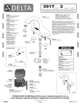
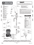
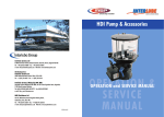
Oil Filtration Systems
Filtakleen By-Pass Oil Filter
INSTALLATION
INSTALLATION
& SERVICE
& SERVICE
MANUAL
MANUAL
xx
INTRODUCTION
The Filtakleen By-Pass oil Filter is an ultra-fine
1 micron Bypass filtration system suitable for
use with a wide range of equipment.
It provides the best possible filtration
protection against system wear, oil
degradation, rust and corrosion. Working in
conjunction with the equipments full flow filter,
the Filtakleen By-Pass Filter removes any
particles in the oil likely to cause system
damage. The Filtakleen Bypass Filter typically
filters all the oil in the system several times an
hour, so the system continuously receives
analytically clean oil.
What are the benefits of the Filtakleen Bypass
Filtration?
UK Headquarters:
Interlube Systems Ltd
St Modwen Road, Parkway Industrial Estate,
Plymouth, Devon, England PL6 8LH
Tel: +44 (0)1752 676000
Fax: +44 (0)1752 676001
e-mail: [email protected]
Web Site: www.interlubesystems.com
USA Headquarters:
Interlube Systems Inc
4696 Wadsworth Road,
Dayton, Ohio, 45414, USA
Tel: + 1 937 276 4507
Fax: + 1 937 276 4518
e-mail: [email protected]
• An extension of Oil Drain and Filter Change
Intervals
• An improvment of Oil cooling
• An increase of filtration quality and so an
extension of the engine life
• An increase in the fluid system capacity
• An efficiencient removal of small particle
and soot
• Reduced cost of oil and full flow filters
• Less wear (up to 90%)
• 1-Micron filtration
• 100% water removal
SYSTEM DESCRIPTION
The By-Pass filter is designed to be used in conjunction with the main in line filter. The system continuously
filters a percentage of the oil, typically 10%, in the circuit which means it is able to provides additional filtration
to a much finer tolerance than the in-line filter. This greatly prolongs the life of both the oil and the main filter
itself.
The filter housing is manufactured as a one piece aluminium anodised body which is powder coated, making it
suitable for all environments, and offering total durability. The lid is secured by a single high tensile bolt which
makes lid removal and filter changing quick and easy. The lid houses an quad ring seal giving completely leak
proof sealing.
The filter cartridge is made from a cellulose fibre based tissue of pure pulp, around a cardboard core.
The cartridge is housed in a nylon stocking with an impressed brass ring to facilitate cartridge removal. The
filter housing is fitted using an adjustable mounting bracket, which offers the installer a wide range of filter
positions and fixing points. The filter is capable of filtering all types of oils with a viscosity range of 9-220cst.
It is also suitable for use with other mediums such as bio fuels and dielectric fluid
Single bolt high tensile steel,
allows for easy cartridge
change
Heavy duty lid seal
Oil flow in filter
Powder coated 1 piece
aluminum body
Bracket fixing allows for
flexible position
Oil inlet Outlet
Filter Cartridge
Filter Core
Universal mounting bracket
Operation
Oil enters the filter via the inlet point and passes up through the core of the filter. The oil then percolates slowly
down through the filter medium, through the outlet, and is returned to the system. Systems for hydraulic oils
will have a pressure reducing manifold fitted to the bottom of the filter body. This reduces to reduce down the
high pressures of a hydraulic system to the operating pressure of the filter. Engine oil systems have no need
for the manifold as they operate at much lower pressures. The standard operating pressure of the filter is
approx 5 bar. The manifold incorporates a pressure relief valve which is factory set at 65psi / 4.45bar. The
manifold has a test point for the attachment of fluid monitoring equipment. A pressure gauge is available as an
option.
3
SYSTEM COMPONENTS
The correct size filter for the application should be confirmed by referring to the application table on page10.
The filter kit comprises a filter assembly including mounting bracket, filter cartridge, and a range of fittings as
listed below. The system is designed to be installed with ?” inlet hose, and 3/8” outlet hose, and fittings to suit
this size hose, plus connections into the filter are provided. With hydraulic systems a ball valve and pressure
reducing manifold are included.
Maxi Duty Hydraulic Kit
Bantam Engine Kit
The following fittings are supplied as part of a kit
Engine Kit
Hydraulic Kit
Qty
17-17067A Ball Valve 1/4 bsp
1
17-17070 R/U 3/8 Swept Elbow
1
17-17055 R/U RIT 3/8 Ferrule
2
17-17092 R/U 1/4 Swept Elbow
1
17-17054 R/U R2T 1/4 Insert
1
17-17052 R/U 1/4 Insert
1
17-17072 R/U 3/8 Insert
1
17-17060 R/U 3/8 90 Degree Elbow
1
17-17069 1/4 90 Degree Swivel Adaptor
1
17-17091 R/U 1/4 90 Degree Compact Elbow 1
17-17016A Manifold block
1
17-17092
17-17052
17-17076
17-17074T
17-17056
R/U 1/4 Swept Elbow
R/U 1/4 Insert
1/4 BSP 1/4 BSP Male Adaptor
1/8 BSP 1/4 BSP Male Adaptor
R/U RIT 1/4 Ferrile
Qty
2
2
2
1
4
Hose and tubing do not come with the kit, and can be ordered separately, please refer to page 11
Please note that additional fittings will be required for installation, the size and type of which will vary according
to the equipment on which the system is to be fitted.
4
SYSTEM INSTALLATION
Entry Points
In principle the take off point should always be on the
main system feed, after the pump. It can be either
before or after the main in-line filter.
Engine oil Systems
Usually located in the oil gallery, many engines have
unused plugs here, or on the oil filter housing.
Another option is to remove the oil pressure sensor
and refit a T-piece adaptor.
The turbo lubrication is usually fed via a banjo-bolt,
which can be replaced by one with an external inlet.
A mechanical fuel pump is fitted with a banjo-bolt
lubrication line too, which can also be replaced by
one with an external inlet. And if necessary, the
compressor lubrication can be used. Each individual
situation will show which is preferable.
In engine oil the temperature can be as high as
120oC. Hoses with single steel braiding and temp
spec of 150oC continuous should be used.
Hydraulic oil temp is normally not more than 80oC so
the emphasis here is pressure. Modern construction
equipment uses up to 450 bar pump pressure, which
can be handled by the Safety Manifold. But the hose
must be 2 steel inlays with working pressure of at
least 650 bars, to compensate for peak pressure.
Mounting the units
Hydraulic Oil Systems
Preferably the units should be mounted with the lid
above the liquid level in the hydraulic tank or the
motor oil sump. This because in the return lines there
are non-return valves and the liquid could overflow
the bowl when opening the lid for cartridge change.
Also the units should be easily accessible from the
front, again for easy change of cartridge.
And lastly, there must be enough space above the
unit to accommodate the cartridge change.
The pressure should be taken from the main pump
circuit, as this is the system which will have the
most working hours, (if more than one pump is
fitted). The units can be fitted to high pressure
systems, up to a maximum of 9000 psi. Use of this
circuit maximises the time available for effective
filtration. Typically this pump has overcapacity, so
that the oil stream taken to the by-pass filter will not
influence the performance of the system. Never take
the pressure from a servo or pilot circuit, because
one cannot predict if certain functions of the system
will be adversely influenced. This may even be
dangerous. Hoses must be rated for the operating
pressure of the equipment.
Brackets should be bolted to the frame of the
equipment. Welding is an option, but some modern
equipment has sophisticated computers, which must
be unplugged completely, before welding starts.
Engine system fitment
Hydraulic system fitment
RETURN
By Pass Filter
TANK
MANIFOLD
IN
OUT
BALL VALVE
Full Flow Filter
FLOW
MAIN PUMP
ENGINE
Returns to Sump
Sump
Connection into main line should be
after pump and can be before or
after in-line filter
INLINE FILTER
5
Pressure Reducing Manifold
The relief valve is factory set at 65psi as this is the
most effective setting for filtration. However in the
event of adjustment being necessary, connect a
pressure gauge to the test point. Turn clockwise to
increase pressure setting, and anti-clockwise to
reduce.
In the majority of cases, on the pressure side of the
main pump, there is a pressure test nipple, which
can be taken out and refitted with a T-piece. If not,
this nipple is situated on the first valve block in the
pump pressure line. Sometimes the pump or the
valve block has loose plugs, which can be replaced
by an adaptor.
Pressure
adjustment
screw
PIC 1
Ball valve
Take off point
In-line filter
If none of these exist somewhere in the main
pressure line, a fitting such as a T- piece or elbow
can be used (e.g. Pic 1). it should be taken off and
drilled and threaded to take a suitable fitting. The ball
valve can be positioned anywhere in the line from the
take off point up to the filter (Pic 2).
Outlet
Filter
Ball valve
PIC 2
When working on a hydraulic system it is preferential
to have the tank air pressure relieved or even better if
a vacuum pump is placed on the tank filler opening
to maintain under pressure in the tank and system
while working. This helps to prevent awkward oil
spills.
6
Inlet
Adjustable
pressure relief
valve
Test point
Return points
Post Installation:
In general there must not be any backpressure in the
return line such as orifices, partial pressures in pilot
systems, etc. The outlet of the by-pass filter should
be zero pressure.
Once the installation is complete, check that all
connections are secure. Confirm that the inlet
(pressure) and outlet (return) hoses are connected to
the correct ports in the filter housing, as failing to do
this will result in inefficient filtering and oil to leak
from the lid of the filter housing. Make sure all pipes
are secured tightly i.e. with tie wraps, especially near
the inlet and outlet adaptors. Run the engine or
equipment making sure that there are no oil leaks
and that oil is passing through the filter.
Engine oil systems
Return points can be found in unused plugs on the
sump (if this is below liquid level use a vacuum
pump on the oil filling point).
Alternatives are:
•the return of the turbo lubrication to the block is
sometimes a banjobolt, which can be replaced.
•on the sump rim is a plug for a second sounding
rod on the opposite side of the block.
•the oil-filling pipe can be removed, drilled and
threaded to fit an adaptor.
•the valve cover can be removed, drilled and fitted
with an adaptor. See that the adaptor outlet is above
the camshaft rod and not over the valve stem. This
results in excessive oil consumption.
Hydraulic oil systems
Return points can be found on the tank return
manifold in unused plugs.
Alternatives are:
•an extra coupling can be drilled, threaded and fitted
with an adaptor, can interrupt leakage lines.
•lines such as knee bends or bulkheads feeds be
removed, drilled and threaded.
Remember this is all low pressure, where some
hydraulic seal compound is enough to prevent oil
spill.
7
CHANGING THE FILTER CARTRIDGE
On Engine systems engine should be switched off
On hydraulic systems turn ball valve to off position (pic 1). The machine need not be switched off.
Undo lid bolt, allowing air to enter system. (pic 2) If the units are mounted above tank level, the bowl will
empty back into the system; this will take a few minutes. Withdraw old cartridge using brass ring (pic 3).
Note: To help prevent oil spill, the bag from the new replacement cartridge can be slid over filter pot and
cartridge withdrawn into it. Insert new filter element without cleaning inside the bowl and push in firmly (pic
4/5). Replace lid seal with the new one provided, (pic 6) and tighten bolt to approx 20lbs/ft. Open ball valve
or restart engine and check system for leaks.
Lid bolt
PIC 1
Lid bolt washer
Lid bolt O ring
Lid
Lid seal
PIC 2
PIC 3
Filter cartridge
PIC 4
Filter body
PIC 5
Heavy Duty
PIC 6
8
CARTRIDGE CHANGE GUIDELINES
Filter element life is dependant on the original oil condition. Figures given are for guidance. If the oil is very dirty,
or a higher level of cleanliness is required, more element changes will be needed. However, the Filtakleen filter
will always purify the oil to a safe re-usable condition, given sufficient element changes. Even totally emulsified
oil will be reclaimed and purified to a better than new condition usually within 4 element changes.
Guidance for cartridge changes
ENGINES
Filtakleen filter change
Bantam
3000m/5000km
500 hours
3 months
2000 hours/annual
3750m/5000km
500 hours
3 months
2000 hours/annual
9300m/15000km
1250 hours
3 months
100000m/160000km/annual
15600m/25000km
1500 hours
3 months
100000m/160000km/annual
Light
Heavy
Maxi
Main filter change
Oil Change
HYDRAULICS
Heavy
500 hours / 3 months
2000 hours/annual
10000 hours/5 years
Maxi
500 hours / 3 months
2000 hours/annual
10000 hours/5 years
Where alternate figures are shown the earliest reached should be used
ENGINES
Change Filtakleen cartridge at every service interval
Change standard oil and filter every 12 months minimum
HYDRAULICS
Change FK cartridge at every maintenance interval
Change standard full flow filters annually
9
SPECIFICATION
Application
Engines
Hydraulics
Product
Bantam
Light
Heavy
Maxi
Heavy
Maxi
Kit
FF368
FF668
FF878
FF988
FFHY778
FFMY788
Filter colour
White
Red
Blue
Blue
Blue
Blue
14 litre
36 litre
72 litre
900 litre
2000 litre
Sump/Tank capacity 8 litre
Flow rate
1.5 l/min
3.0 l/min
4.5 l/min
6 l/min
4.5 l/min
6 l/min
Filter Body
Aluminium
Aluminium
Aluminium
Aluminium
Aluminium
Aluminium
Weight (exc fittings)
1.5 kg
1.8 kg
2.8 kg
3.9 kg
3.3 kgs
4.4 kg
Inlet connection
1/4 bsp
1/4 bsp
1/4 bsp
1/4 bsp
1/4 bsp
1/4 bsp
Outlet connection
1/4 bsp
1/4 bsp
1/4 bsp
1/4 bsp
3/8 bsp
3/8 bsp
Inlet Pressure
4.45 bar (65psi)
4.45 bar (65psi)
4.45 bar (65psi)
4.45 bar (65psi)
350 bar (5000psi) 350 bar(5000psi)
Internal pressure
4.45 bar (65psi)
4.45 bar (65psi)
4.45 bar (65psi)
4.45 bar (65psi)
4.45 bar (65psi)
4.45 bar (65psi)
Max Oil temp *
79ºC
79ºC
79ºC
79ºC
79ºC
79ºC
Viscosity range
9-220cST
9-220cST
9-220cST
9-220cST
9-220cST
9-220cST
Cartridges
PART No
C58
C68
HYC78
MYC88
HYC78
MYC88
Height
78mm
114mm
114mm
114mm
114mm
114mm
190mm
Diameter
102mm
102mm
145mm
190mm
145mm
Filter Length
102m
114m
272M
460m
272m
Surface area
80,000 sq cm
130,000 sq cm
490,000 sq cm
524,000 sq cm
490,000 sq cm
524,000 sq cm
Weight
184g
300g
630g
1060g
630g
1060g
460m
*Recomended maximum operating temperature. Filter can operate at higher temperatures but filter life may be affected
A
SPARES
FF368 Bantam Duty
Description
Part number
Cartridge
Lid
Lid Seal
Lid Bolt
Lid Bolt
Lid Bolt O Ring
Dowty Seal
C58-1717058
17-17008
17-17046
17-17025
17-17051
17-17045
25131-003
B
C
Dimensions (mm)
A
B
C
Bantam
115
200
88
above sizes are approximate
10
Light
115
240
88
Heavy
166
275
105
Maxi
213
297
127
SPARES continued
FF668 Light Duty
Description
Cartridge
Lid
Lid Seal
Lid Bolt
Lid Bolt Washer
Lid Bolt O Ring
Dowty Seal
Part number
C68-1717068
17-17005
17-17046
17-17024
17-17051
17-17045
25131-003
FF878 / FFHY778 Heavy Duty
Description
Cartridge
Lid
Lid Seal
Lid Bolt
Lid Bolt Washer
Lid Bolt O Ring
Part number
HYC78-1717078
17-17001
17-17047
17-17023
17-17051
17-17045
FF988/FFMY778 Maxi Duty
Description
Cartridge
Lid
Lid Seal
Lid Bolt
Lid Bolt Washer
Lid Bolt O Ring
Part number
MYC88-1717088
17-17002
17-17048
17-17023
17-17051
17-17045
Filter Fittings
Description
1/4 x 1/4 bsp male
1/4 x 1/8 bsp male
Part number
17-17076
17-17074T
Hydraulic Systems Parts
Description
Manifold Block
1/8 x 1/4 bsp restrictor inlet adaptor
1/8 x 3/8 bsp outlet adaptor
1/8 Dowty Seal
Ball Valve
1/4" R1 Hose
1/4" R2 Hose
3/8" R1 Hose
Part number
MYC78-1717088
17-17084
17-17077
14-20685
17-17067A
17-17059
17-17058
17-17057
11
Oil Filtration Systems
Interlube Systems Ltd
St Modwen Road, Parkway Industrial Estate, Plymouth,
Devon, England PL6 8LH
Tel: +44 (0)1752 676000 Fax: +44 (0)1752 676001
e-mail: [email protected]
Web Site: www.interlubesystems.com
USA Headquarters:
Interlube Systems Inc
Distributed by
4696 Wadsworth Road, Dayton, Ohio, 45414, USA
Tel: +1 (937) 276 4507 Fax: +1 (937) 276 4518
Filtakleen Inc
514 West 8360 South, Sandy, UT, 84070, USA
Tel: +1 (801) 233 9185 Fax: +1 (801) 233 2876
Toll Free 1-877-464-5728
www.interlubesystems.com