1
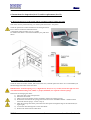
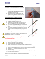
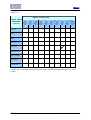
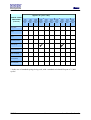
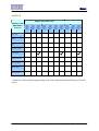
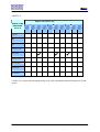
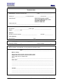
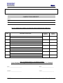
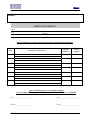
Maintenance and Service Manual For industrial sectional overhead doors with torsion springs V1.0 UK Manual Contents 1 Symbols and warning signs 3 2 General: 3 3 Safety instructions for maintenance and service 3 4 Maintenance in general 4.1 Schedules 4.2 Inspection and replacement levels 4.3 Inspection (level 1) 4.4 Inspection (level 2) or replacement (level 2) 3 4 4 4 4 5 Inspection items (level 2) and/or replacement (level 2) 4 6 Instructions for inspection (level 2) and/or replacement (level 2) 6.1 Measuring the forces on the safety edge in accordance with EN 12445 / EN 12453 6.2 Checking and/or replacing the lifting cables 6.3 Checking and/or replacing rollers 6.4 Checking and/or replacing side and intermediate hinges 6.5 Checking and/or replacing the side bearing brackets 6.6 Checking door balance / replacing torsion springs 6.7 Checking and/or replacing spring break devices 6.8 Checking and adjusting the play between door blade and seals 6.9 Checking the bottom seal 6.10 Checking the side and lintel seals 5 5 6 6 6 7 7 8 9 9 9 7 The manufacturer /maintenance company 9 Annex: A Schedule: parts to be replaced (approx. 5 cycles / day) Annex: B Schedule: parts to be replaced (approx. 10 cycles / day) Annex: C Schedule: parts to be replaced (approx. 15 cycles / day) Annex: D Schedule: parts to be replaced (approx. 20 cycles / day) Annex: E Schedule: parts to be replaced (approx. 25 cycles / day) Form: Technical data Form: Inspection report UK V1.0 2 10 11 12 13 14 15 16 www.doco-international.co.uk Manual 1. Symbols and warning signs General symbol for DANGER !! Symbol for ATTENTION !! Read carefully the text with this symbol!! Symbol: Risk of physical injury!! Read carefully the text with this symbol!! 2. General: This maintenance manual has been prepared for use by qualified personnel and therefore not by trainees or “do it yourselfers” In case of doubt about the maintenance or servicing instructions, please contact DOCO International. To avoid severe personal injury, carefully read and observe all indications and warnings in this maintenance manual. This manual has been compiled in accordance with EN 12635, however, you should check yourself as to whether this standard corresponds with the local national standards. 3. Safety instructions for maintenance and service - - - - This manual describes the maintenance servicing of industrial sectional overhead doors with torsion springs; this may be supplemented by other maintenance manuals, for instance the door operator manual (if applicable.) Adding or leaving out parts can affect the working and therefore the safety of the garage door and is therefore strongly prohibited ! All indications concerning the assembly right or left are always viewed from the assembly location, that is from the inside to the outside! All measures are in millimetres unless otherwise specified. Keep this maintenance manual in a safe place. Make sure that the power is switched off and remains switched off while (electrical) work is carried out! Some parts contain sharp edges: use protective gloves. When performing maintenance to the industrial door, always wear at least gloves and safety boots. During drilling; wear safety goggles! Make sure that you can always perform your work in a stable environment, if necessary; use scaffolding. Secure the assembly/maintenance area with safety tape to keep others at a distance. Make sure there is enough light. Only use appropriate tools, especially when tensioning the torsion springs. Subject to technical changes, without written notice. 4. Maintenance in general In accordance with CE directives, all industrial doors must be checked from the first instance they are being used and with servicing intervals as indicated by the supplier. Servicing and/or maintenance inspection must be recorded in writing. Service and/or maintenance inspections must be carried out by an installation professional or company. UK V1.0 3 www.doco-international.co.uk Manual 4.1 Schedules This manual includes two schedules. A schedule for 1) Inspection schedule 2) Replacement schedule Inspection mainly means that checks have to be performed. Replacement means that parts MUST be replaced in accordance with a schedule!! These schedules have been drawn up based on investigation and endurance testing. The replacement schedules have been set up in relation to frequency of use. 4.2 Inspection and replacement levels Inspection and/or maintenance can be divided into two levels: Level 1: Maintenance that may be carried out by the end user (caretaker) himself! Level 2: Maintenance that must be carried out by a qualified company and must be recorded in writing! 4.3 Inspection (level 1) This inspection must be performed once every 10,000 cycles or once a year. - Hinges and rollers must be given a single drop of oil (SAE 20 quality). Check the cables for tears or damage. Clean the tracks. 4.4 Inspection (level 2) or Replacement (level 2) Inspection (level 2) must be performed once a year (or at lesser intervals as required by the frequency of operation) by a qualified company and must be recorded in writing in accordance with: Inspection Report Replacement (level 2) must be performed in accordance with the replacement schedule (see Annexes A through E) by a qualified company and must be recorded in writing in accordance with: Inspection Report 5 Inspection items (level 2) and/or replacement (level 2). 1) Measuring the closing edge forces in accordance with EN12445/EN12453 2) Checking and/or replacing the lifting cables 3) Checking and/or replacing rollers 4) Checking and/or replacing the side and intermediate hinges 5) Checking and/or replacing the side bearing brackets 6) Checking the door balance / replacing torsion springs 7) Checking and/or replacing spring break devices 8) Checking and adjusting the play between door blade and seals 9) Checking the bottom seal 10) Checking the side and lintel seals 11) Checking electronic safety switches for spring- and cable safetydevices UK V1.0 4 instructions see 6.1 instructions see 6.2 instructions see 6.3 instructions see 6.4 instructions see 6.5 instructions see 6.6 instructions see 6.7 instructions see 6.8 instructions see 6.9 instructions see 6.10 instructions see 6.11 www.doco-international.co.uk Manual 6. Instructions for inspection (level 2) and/or replacement (level 2) 6.1 Measuring the forces on the closing side in accordance with EN 12445 / EN 12453 This check must be performed using a so-called “peak-force meter”. See photo. Check the peak forces as described below: See the figure below. Forces must be within the established norm! A maximum of 400 N within 0.75 sec.! (graph) For further information: consult the manual for your peak force meter! 6.2 Checking and/or replacing the lifting cables Check the cables for broken strands, kinks and visible wear, if found replace the cables. It is recommended you should change both cables at the same time. IMPORTANT: Tensioned springs carry a high tension; always be very careful, and use the right size and well maintained tensioning rods (12025) - 2 people (minimum) are required to tension springs. Instructions for changing the cables: 1) Move the door to the closed position 2) Block the door blade. 3) Make a note of the number of turns required to tension the existing springs 4) Release the tension from the springs (see instructions in the installation manual - industrial doors fitted with torsion springs - section 7 step 1) 5) Mark the existing cable at the point where the cable passes through the edge of the cable drum (see figure right) 6) Loosen the cable locking bolts on the cable drum. 7) Remove the cable from the cable drum. UK V1.0 5 www.doco-international.co.uk Manual 8) Remove the safety cap from the cable break device. 9) Remove the eye of the cable from the cable break device. 10) Measure from the bottom of the eye to the mark made in 4) on the old cables. 11) Mark a corresponding mark on the new pair of cables. 12) Fit the eye of the new cables onto the cable break bottom corner brackets. 13) Pass the cable from the cable break device behind the rollers to the cable drum. 14) Pass slack cable through cable fixing hole and secure the cable by tightening the plain bolt (not coloured red). 15) Then secure the cable drum including the key onto the shaft by tightening the bolts (red). 16) Once again: Ensure the position of the left and right cable drum is the same and that the cable tension of both cables is equal! 17) To tension springs refer to instructions in the installation manual - industrial doors fitted with torsion springs - section 4.13) 6.3 Checking and/or replacing rollers Instructions for checking rollers: 1) Remove a roller from the side hinge by undoing the two bolts on the roller carrier and sliding the roller out. 2) Take the roller into your hand and check whether the roller can be turned without it making a “snapping” sound. This sound indicates a worn ball-bearing. Replace the roller. 3) Also check the axial play of the bearing. See photo, if there is more than 0.5 mm of play, replace the roller. Instructions for replacing rollers: 1) Remove a roller from the side hinge by undoing the two bolts on the roller carrier and sliding the roller out. 2) Insert the new roller into the roller carrier, position roller into track and bolt roller holder onto the roller carrier. Adjust in accordance with instruction 6.8. 6.4 Checking and/or replacing the side and intermediate hinges Check the hinges for breaks (see photo, marking 1), also check the hinge bolt, this should not have worked its way out of the hinge (see photo, marking 2). Instructions for replacing rollers: 1) Dismount the side or intermediate hinge by loosening the self-tapping fasteners. 2) Mount the new side or intermediate hinge by tightening the self-tapping fasteners. 3) Torque for side hinge: 15 Nm. 4) Torque for intermediate hinge: 10 Nm. UK V1.0 6 www.doco-international.co.uk Manual 6.5 Checking and/or replacing the side bearing brackets These can only be checked if the torsion springs are removed! Check whether play in the bearing is still within acceptable limits. 1) Turn the bearing with your finger and listen for a “snapping” sound. This sound indicates a worn ballbearing. Replace the bearing plate. 2) Check the axial play. Use your finger for this. This should be no more than 0.5 mm. If there is more play replace the bearing plate. 6.6 Checking door balance / replacing torsion springs Instructions for testing door balance: 1) Move the door in closed position 2) Disengage the door operator (if applicable). 3) Position the door blade in any given position. 4) The door blade must remain in this position. Should the door blade rise or fall, the torsion springs need to be readjusted. 5) In the case of a door blade falling, the torsion springs need to be tightened. Do this by tightening each spring 0.25 turn each time, until the door blade is balanced. (see correcting the spring tension) 6) In the case of a door blade rising, the torsion springs need to be loosened. Do this by loosening each spring 0.25 turn each time, until the door blade is balanced. (see correcting the spring tension) Correcting the spring tension Block the shaft and the door blade. Secure the door in such a way that it cannot rise. Do so, for instance, by fastening self-grip wrenches on the vertical tracks. IMPORTANT: There is great strain on tensioned springs; proceed carefully at all times, especially when performing corrective maintenance. Use tensioning bars that are well fitting and that have been well maintained (12025). You can correct the tension by stretching or releasing the spring with 1 full turn (4 x 0.25 turns) at the most. Make sure that both springs are equally corrected. 1) 2) 3) 4) 5) 6) 7) 8) 9) 10) Insert the first tensioning bar in the winding plug. Turn the tensioning bar in the appropriate direction. Carefully loosen the bolts of the winding plug and take over the spring tension. Remove the steel key. Hold the first tensioning bar and place the second bar in the next hole of the winding plug. Turn the second tensioning bar a quarter of a turn in the desired direction. Hold the second tensioning bar (takes over the tension) and remove the first tensioning bar. Repeat steps 4 - 5 - 6 until the correct tension has been reached. Replace the steel key Secure the winding plug on the shaft by turning both bolts of the winding plug with 27 up to max. 34 Nm. 11) Now remove the last tensioning bar. Remove the block from the shaft and the vertical tracks and check the balance. UK V1.0 7 www.doco-international.co.uk Manual Instructions for replacing torsion springs. IMPORTANT: There is great strain on tensioned springs; proceed carefully at all times, especially when performing corrective maintenance. Use tensioning bars that are well fitting and that have been well maintained (12025). 1) Block the shaft and the door blade. Secure the door in such a way that it cannot rise. Do so, for instance, by fastening self-grip wrenches on the vertical tracks 2) Insert the first tensioning bar in the winding plug. 3) Turn the tensioning bar in the appropriate direction. 4) Carefully loosen the bolts of the winding plug and take over the spring tension. 5) Remove the steel key. 6) Hold the first tensioning bar and place the second bar in the next hole of the winding plug. 7) Turn the second tensioning bar in the desired direction. 8) Hold the second tensioning bar (takes over the tension) and remove the first tensioning bar. 9) Repeat steps 4 - 5 - 6 until the spring has been de-tensioned. 10) Loosen the cable fixing bolts on the cable drum and remove the cable. 11) Loosen the bolts of the coupler (if fitted). 12) Loosen the bolts (B) which fix the spring break device to the construction. Should the spring break device (25449) be fixed by means of an offset plate (25448), only loosen bolts (A) (see photograph). 13) Now slide the complete shaft or “half shaft” from the side bearing bracket. Do this on the other side in the same manner. 14) Disassemble the torsion springs of the spring break device (25449) on the ground. 15) First, check the side bearing brackets and the bearings of the spring break device (25449) in accordance with instruction 6.5 16) Slide the new torsion springs over the shaft and fix them in accordance with the installation manual (see installation manual industrial sets of fittings 4.10.10 and installation manual spring break devices 25449). 17) Slide the complete shaft or “half shaft” (both), back into the side bearing bracket and fix to the construction or offset plate again using bolts A or B. 18) Fix both shafts together again by means of the coupler (where fitted). 19) Now Position the cable drum and mount the cable (see instructions in the installation manual industrial sets of fittings with torsion springs 4.13). 20) Block the shaft with the self-grip wrenches. UK V1.0 8 www.doco-international.co.uk Manual 21) Tension the torsion springs in accordance with instructions (see installation manual industrial sets of fittings with torsion springs 4.14). 22) Remove the self-gripping wrenches and test the door. (see 6.5) 6.7 Checking and/or replacing spring break devices These can only be checked if the torsion springs are removed! Check the play in the bearings in accordance with 6.5 and the way they function (see installation manual spring break device 25449 ) 6.8 Checking and adjusting the play between door blade and seals Check whether the play between the door blade and side seals is still correct. Play should be just be sufficient as to allow the rollers to rotate freely If a finger guard (25700) has been fitted, this can only be checked by readjusting the roller carrier. Instructions for readjusting the play of the door blade. 1) Loosen the bolts of the roller carrier. 2) Use one hand to put pressure onto the door blade and, with the other hand, adjust the roller with the roller carrier in such a manner that the roller carrier is pushed against the track (with a little tension). 3) Use one hand to maintain tension on the roller carrier and retighten the roller carrier nuts. Do this for all side hinges! 6.9 Checking the bottom seal (80045) In accordance with EU standard EN13241-1 the seals around the door blade need to be in perfect condition in order to retain the classification obtained through testing. Check the seals for flexibility and sealing characteristics. The sealing characteristics can be checked by closing the door blade. The bottom seal should be sealed, even in the case of slight unevenness. 6.10 Checking the side and lintel seals (24740) In accordance with EU standard EN13241-1 the seals around the door blade need to be in perfect condition in order to retain the classification obtained through testing. Check the seal for flexibility and wear, there must not be any holes in the seals. 6.11 Checking electronic safety switches for spring- and cable safetydevices In accordance with EN 12604 cable and springsafetydevices have to be equiped with electrical switches. In case off spring or cable break the motor has to switch off (see page 17 for the article numbers). 7 The manufacturer DOCO International Limited Unit K4 The Metropolitan Centre Field Way Greenford Middlesex UB6 8UN T: 0044 208 8132266 F: 0044 208 8132288 E: [email protected] UK V1.0 9 www.doco-international.co.uk Manual ANNEX: A Approx. 5 cycles a day PARTS TO BE REPLACED (Level 2) 1,800 cycles approx. 1 year 3,600 cycles approx. 2 years 5,400 cycles approx. 3 years 7,200 cycles approx. 4 years 9,000 cycles approx. 5 years 10,800 cycles approx. 6 years 12,600 cycles approx. 7 years 14,400 cycles approx. 8 years 16,200 cycles approx. 9 years 18,000 cycles approx. 10 years Lifting cables Rollers Side and intermediate hinges Side bearing brackets Torsion springs Spring break devices Bottom seal (80042) Side seal (24740) Lintel seal (24740) * In the case of standard springs being used, with a standard calculated lifespan of 15,000 cycles! UK V1.0 10 www.doco-international.co.uk Manual ANNEX: B Approx. 10 cycles a day PARTS TO BE REPLACED (Level 2) 3,600 cycles approx. 1 year 7,200 cycles approx. 2 years 10,800 cycles approx. 3 years 14,400 cycles approx. 4 years 18,000 cycles approx. 5 years 21,600 cycles approx. 6 years 25,200 cycles approx. 7 years 28,800 cycles approx. 8 years 32,400 cycles approx. 9 years 36,000 cycles approx. 10 years Lifting cables Rollers Side and intermediate hinges Side bearing brackets Torsion springs Spring break devices Bottom seal (80042) Side seal (24740) Lintel seal (24740) * In the case of standard springs being used, with a standard calculated lifespan of 15,000 cycles! UK V1.0 11 www.doco-international.co.uk Manual ANNEX: C Approx. 15 cycles a day PARTS TO BE REPLACED (Level 2) 5,400 cycles approx. 1 year 10,800 cycles approx. 2 years 16,200 cycles approx. 3 years 21,600 cycles approx. 4 years 27,000 cycles approx. 5 years 32,400 cycles approx. 6 years 37,800 cycles approx. 7 years 43,200 cycles approx. 8 years 48,600 cycles approx. 9 years 54,000 cycles approx. 10 years Lifting cables Rollers Side and intermediate hinges Side bearing brackets Torsion springs Spring break devices Bottom seal (80042) Side seal (24740) Lintel seal (24740) * In the case of standard springs being used, with a standard calculated lifespan of 15,000 cycles! UK V1.0 12 www.doco-international.co.uk Manual ANNEX: D Approx. 20 cycles a day PARTS TO BE REPLACED (Level 2) 7,200 cycles approx. 1 year 14,400 cycles approx. 2 years 21,600 cycles approx. 3 years 28,800 cycles approx. 4 years 36,000 cycles approx. 5 years 43,200 cycles approx. 6 years 50,400 cycles approx. 7 years 57,600 cycles approx. 8 years 64,800 cycles approx. 9 years 72,000 cycles approx. 10 years Lifting cables Rollers Side and intermediate hinges Side bearing brackets Torsion springs Spring break devices Bottom seal (80042) Side seal (24740) Lintel seal (24740) * In the case of shot-blasted springs being used, with a standard calculated lifespan of 25,000 cycles! UK V1.0 13 www.doco-international.co.uk Manual ANNEX: E Approx. 25 cycles a day PARTS TO BE REPLACED (Level 2) 9,000 cycles approx. 1 year 18,000 cycles approx. 2 years 27,000 cycles approx. 3 years 36,000 cycles approx. 4 years 45,000 cycles approx. 5 years 54,000 cycles approx. 6 years 63,000 cycles approx. 7 years 72,000 cycles approx. 8 years 81,000 cycles approx. 9 years 90,000 cycles approx. 10 years Lifting cables Rollers Side and intermediate hinges Side bearing brackets Torsion springs Spring break devices Bottom seal (80042) Side seal (24740) Lintel seal (24740) * In the case of shot-blasted springs being used, with a standard calculated lifespan of 25,000 cycles! UK V1.0 14 www.doco-international.co.uk Manual Technical data 1. Description: Industrial sectional door Type: _____________________ Factory nr..: __________________ Yr manufactured.: __________ First use on: ___________ Manufacturer: DOCO International Limited. Unit K4 The Metropolitan Centre Field Way Greenford Middlesex UB6 8UN Client and town: _____________________________________________________ _____________________________________________________ 2. Door blade : Dimensions: ________________________Panel type: _____________________________ Weight : ___________Kg, 3. Balance : Number of torsion springs : __________________________ Number :______________ 4. Door operator : Manufacturer: _________________________ Power: _________ kW RPM Type:_____________________________ : _________min Operating voltage: _____ V -1 Control voltage : _________V 5. Type of control: Way to operate: Pushbutton Key switch Remote control Other :___________________________________________________ 6. Built-in safety: Spring break device 25449; electrical switch 25447. Cable break device 25453; electrical switch 25445 Safety edge device :FRABA OSEOther __________________________________________________________________ Other data: _____________________________________________________________ ________________________________________________________________________ ________________________________________________________________________ ________________________________________________________________________ 7. Installer:________________________________________________________________ ________________________________________________________________________ ________________________________________________________________________ UK V1.0 15 www.doco-international.co.uk Manual Installer : INSPECTION REPORT Product : (model, type, serial number, etc.) Client: (address) name, address and contact LIST OF INSPECTED ITEMS IN ACCORDANCE WITH MAINTENANCE MANUAL: Date Description of work done Installer’s signature Client’s signature Any work done must be recorded in writing! Copy this page for every periodic inspection and file it with the User Manual! Date :_______________________ Date :_______________________ Installer :____________________ Client :______________________ UK V1.0 16 www.doco-international.co.uk Manual Installer : INSPECTION REPORT Product : (model, type, serial number, etc.) Client: (address) name, address and contact LIST OF INSPECTED ITEMS IN ACCORDANCE WITH MAINTENANCE MANUAL: Date Description of work done Installer’s signature Client’s signature Any work done must be recorded in writing! Copy this page for every periodic inspection and file it with the User Manual! Date :_______________________ Date :_______________________ Installer :____________________ Client :______________________ UK V1.0 17 www.doco-international.co.uk Manual Installer : INSPECTION REPORT Product : (model, type, serial number, etc.) Client: (address) name, address and contact LIST OF INSPECTED ITEMS IN ACCORDANCE WITH MAINTENANCE MANUAL: Date Description of work done Installer’s signature Client’s signature Any work done must be recorded in writing! Copy this page for every periodic inspection and file it with the User Manual! Date :_______________________ Date :_______________________ Installer :____________________ Client :______________________ UK V1.0 18 www.doco-international.co.uk Manual Installer : INSPECTION REPORT Product : (model, type, serial number, etc.) Client: (address) name, address and contact LIST OF INSPECTED ITEMS IN ACCORDANCE WITH MAINTENANCE MANUAL: Date Description of work done Installer’s signature Client’s signature Any work done must be recorded in writing! Copy this page for every periodic inspection and file it with the User Manual! Date :_______________________ Date :_______________________ Installer :____________________ Client :______________________ UK V1.0 19 www.doco-international.co.uk