1
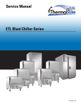
SERVICE
MANUAL
Out 1
Out 2
ADD FLUID
ADD FLUID
MODELS
200NDNL
200CT
250PNDT
300NDNL
300CT
300OC
700NDNL
725NDNL
950NDNL
957 NDNL
1600NDNL
BW3S NDNL
For additional information on Thermodyne Foodservice Products, Inc.,
or to locate an authorized parts and service provider in your area,
visit our website at www.tdyne.com.
Please visit our website to Register your Thermodyne unit. Registration ensures that you
get up-to-date warranty and product information, along with fast and convenient service.
http://www.tdyne.com/register.aspx
Thermodyne Foodservice Products, Inc.
4418 New Haven Avenue
Fort Wayne, IN 46803
(08 -12)
1-800-526-9182
www.tdyne.com
ELECTRICAL WARNINGS
THIS MANUAL HAS BEEN PREPARED FOR PERSONNEL QUALIFIED TO INSTALL ELECTRICAL
EQUIPMENT, WHO SHOULD PERFORM THE INITIAL FIELD STARTUP AND ADJUSTMENTS OF
THE EQUIPMENT COVERED BY THIS MANUAL.
READ THIS MANUAL THOROUGHLY BEFORE OPERATING, INSTALLING OR PERFORMING
MAINTENANCE ON THE EQUIPMENT.
WARNING: Failure to follow all the instructions in this manual can cause property
damage, injury or death.
WARNING: Improper installation, adjustment, alteration, service or maintenance can
cause property damage, injury or death.
WARNING: Electrical connections should be performed only by a certified professional.
WARNING: Electrical and grounding connections must comply with the applicable
portions of the National Electric Code and/or all local electric codes. Failure to comply with this
procedure can cause property damage, injury or death.
WARNING: Before connecting the unit to the electrical supply, verify that the electrical
and grounding connections comply with the applicable portions of the National Electric Code
and/or other local electrical codes. Failure to comply with this procedure can cause property
damage, injury or death.
WARNING: Before connecting the unit to the electrical supply, verify that the electrical
connection agrees with the specifications on the data plate. Failure to comply with this
procedure can cause property damage, injury or death.
WARNING: UL73 grounding instructions: This appliance must be connected to a
grounded, metal, permanent wiring system. Or an equipment-grounding conductor must be run
with the circuit conductors and connected to the equipment-grounding terminal or lead on the
appliance. Failure to comply with this procedure can cause property damage, injury or death.
WARNING: Appliances equipped with a flexible electric supply cord, are provided with
a three-prong grounding plug. It is imperative that this plug be connected into a properly
grounded three-prong receptacle. Failure to comply with this procedure can cause property
damage, injury or death.
WARNING: If the receptacle is not the proper grounding type, contact an electrician. Do
not remove the grounding prong from the plug. Failure to comply with this procedure can cause
property damage, injury or death.
——
WARNING: Before performing any service that involves electrical connection or
disconnection and/or exposure to electrical components, always perform the Electrical
LOCKOUT/TAGOUT Procedure. Disconnect all circuits. Failure to comply with this procedure
can cause property damage, injury or death.
WARNING: Before removing any sheet metal panels, always perform the Electrical
LOCKOUT/TAGOUT Procedure. Be sure all circuits are disconnected. Failure to comply with this
procedure can cause property damage, injury or death.
WARNING: Do not operate this equipment without properly placing and securing all
covers and access panels. Failure to comply with this procedure can cause property damage,
injury or death.
WARNING: Do not use or store gasoline or other flammable vapors or liquids in the
vicinity of this or any other appliance. Failure to comply can cause property damage, injury or
death.
WARNING: In the event of a power failure, do not attempt to operate this appliance.
Failure to comply can cause property damage, injury or death.
——
TABLE OF CONTENTS
ELECTRICAL WARNINGS................................................................................................................................ 2
ELECTRICAL LOCKOUT/TAGOUT PROCEDURE.......................................................................................... 5
COVERS AND PANELS.................................................................................................................................... 6
Top Fill Cover.............................................................................................................................................. 6
Power Head Lid.......................................................................................................................................... 6
Units with Doors.......................................................................................................................................... 6
COMPONENT LOCATOR................................................................................................................................. 7
Power Head Components........................................................................................................................... 7
Delivery Manifold Components................................................................................................................... 8
Return Manifold Components..................................................................................................................... 9
COMPONENT REMOVAL AND REPLACEMENT........................................................................................... 10
Electrical Components.............................................................................................................................. 10
Power Toggle Switch................................................................................................................................. 10
Add Fluid Light...........................................................................................................................................11
Temperature Controller..............................................................................................................................11
Cooling Fan............................................................................................................................................... 12
Power Cord............................................................................................................................................... 13
POWER BOARD COMPONENTS.................................................................................................................. 13
Solid State Relay...................................................................................................................................... 13
120VAC Float Board................................................................................................................................. 14
300NDNL Twelve Button Timer............................................................................................................. 15
Plumbing Components........................................................................................................................... 16
B&G Pump................................................................................................................................................ 16
Teflon Hoses............................................................................................................................................. 17
Fluid Level Probes.................................................................................................................................... 18
Snap Disc.................................................................................................................................................. 20
Thermocouple........................................................................................................................................... 20
Heat Elements.......................................................................................................................................... 22
MAINTENANCE PROCEDURES.................................................................................................................... 24
Temperature Controller Set Up Procedures.............................................................................................. 24
Keypad Operation..................................................................................................................................... 24
Unlock the Controller................................................................................................................................ 24
Set-Up....................................................................................................................................................... 24
To Toggle Between °F and °C Readout.................................................................................................... 25
Changing the Heat Transfer Fluid............................................................................................................. 25
CT Door Adjustment.................................................................................................................................. 25
Stainless Steel Care................................................................................................................................. 26
TROUBLESHOOTING.................................................................................................................................... 27
WIRING SCHEMATIC..................................................................................................................................... 28
Fluid Capacities (Standard Shelf Configuration)...................................................................... 30
WARRANTY.................................................................................................................................................... 31
HEAT TRANSFER FLUID MSDS.................................................................................................................... 31
——
ELECTRICAL LOCKOUT/TAGOUT PROCEDURE
1. In electrical box, place appliance circuit breaker
into OFF position.
WARNING: Before performing any
service that involves electrical connection
or disconnection and/or exposure to
electrical components, always follow the
Electrical LOCKOUT/TAGOUT Procedure.
Disconnect all circuits. Failure to comply
can cause property damage, injury or death.
2. Place a lock or other device on electrical box
cover to prevent someone from placing circuit
breaker ON.
3. Place a tag on electrical box cover to indicate
that appliance has been disconnected for
service and power should not be restored until
tag is removed by maintenance personnel.
The Electrical LOCKOUT/TAGOUT Procedure is
used to protect personnel working on an electrical
appliance. Before performing any maintenance
or service that requires exposure to electrical
components, follow these steps:
4. Disconnect appliance power cord from
electrical outlet.
5. Place a tag on the cord to indicate that unit
has been disconnected for service and power
should not be restored until tag is removed by
maintenance personnel.
——
COVERS AND PANELS
Top Fill Cover
Under normal circumstances it is not necessary to
remove the Back Panel to access components. The
exception to this is the BW3SNDNL model. The
Back Panel on the BW3SNDNL provides access
to the Heater Tank components and the Pump.
The Top Fill Cover provides access to the Reservoir
Tank Cap without the requirement to remove the
entire Power Head Lid. Remove the cover to
access the Reservoir Tank Cap when the Add
Fluid Light is illuminated.
The Back Panel on the 950NDNL and 957NDNL
may be lifted off to provide pass through
access.
1. Place the Power Switch in its OFF position.
2. Remove the Philips screws securing the Top
Fill Cover.
1. Follow the LOCKOUT/TAGOUT procedure.
2. Remove the Philips screws securing the Back
Panel.
3. Remove the Top Fill Cover.
3. Lift the Back Panel up and away from the
unit.
Power Head Lid
WARNING
Units with Doors
Before removing any sheet metal panels,
always perform the Electrical LOCKOUT/
TAGOUT Procedure. Be sure all circuits are
disconnected. Failure to comply with this
procedure can cause property damage,
injury or death.
All CT models are supplied with doors. The doors
are provided with lift off hinges. To remove the
doors, open the slightly and lift it straight up and
off the hinge.
——
COMPONENT LOCATOR
Power Head Components
12
13
17
14
15
16
1
3
4
15
5
11
10
9
8
1 2
3 4
5 6
6
7 8
9 10
11 12
7
ADD FL
UID
Figure 1: Power Head Components
1. Cooling Fan
10.120VAC Float Board
2. B&G Pump
11.Neutral Lug
3. Reservoir Fill Cap
12.Heater Elements
4. Reservoir Assembly
13.Snap Disc
5. Contactor
14.16 PSI Pressure Cap
6. Lighted Power Toggle Switch
15.Fluid Level Probes
7. Add Fluid Light
16.Thermocouple
8. Temperature Controller
17.Heater Tank Assembly
9. Solid State Relay
——
2
Delivery Manifold Components
1
2
3
7
4
6
5
Figure 2: Delivery Manifold Components
1. Delivery Line
2. Teflon Washer
3. Shelf Plug
4. Power Cord
5. Delivery Manifold Assembly
6. Short Teflon Hose
7. Shelf Elbow
——
Return Manifold Components
1
2
8
3
4
7
6
Figure 3: Return Manifold Components
1. Overflow Tube
2. Shelf Plug
3. Teflon Washer
4. Drain Tube
5. Drain Tube ON/OFF Valve
6. Return Manifold
7. Long Teflon Hose
8. Shelf Elbow
——
5
COMPONENT REMOVAL AND REPLACEMENT
Electrical Components
Spring
Tab
WARNING
Before removing any sheet metal panels
or servicing this equipment, always
perform the Electrical LOCKOUT/TAGOUT
Procedure. Be sure all circuits are
disconnected. Failure to comply with this
procedure can cause property damage,
injury or death.
Power
Toggle
Switch
WARNING
Certain components may be hot if the
unit was in operation prior to performing
a procedure. Allow the unit to cool before
beginning work.
Figure 4: Power Toggle Switch
Power Toggle Switch
1. Follow the LOCKOUT/TAGOUT procedure
using the procedures provided in the Lockout/
Tagout Procedures section of this manual.
2. Remove the Power Head Lid following the
instructions provided in the Panels and
Covers section of this manual.
3. Tag and disconnect the wires connected to
the Power Toggle Switch
4. Squeeze the spring tabs that hold the switch
in place and push the switch through the front
of the unit.
NOTE: If the switch being removed is damaged,
it may be easier to break the spring tabs
off of the switch rather than attempting to
squeeze the spring tabs. If this method is
used, remember to remove the broken
tabs from the inside of the Power Head.
5. Insert the new switch through the front of the
unit ensuring the tabs have locked in place.
6. Referring to the tags or Circuit Schematic
reconnect all of the wires.
7. Restore power to the unit and check the switch
for proper operation.
8. Remove the units from power.
9. Replace the Power Head Lid.
10.Restore power to the unit and verify proper
operation.
WARNING
Before removing any sheet metal panels
or servicing this equipment, always
perform the Electrical LOCKOUT/TAGOUT
Procedure. Be sure all circuits are
disconnected. Failure to comply with this
procedure can cause property damage,
injury or death.
WARNING
Certain components may be hot if the
unit was in operation prior to performing
a procedure. Allow the unit to cool before
beginning work.
— 10 —
Add Fluid Light
8. Remove the units from power.
1. Follow the LOCKOUT/TAGOUT procedure
using the procedures provided in the Lockout/
Tagout Procedures section of this manual.
9. Replace the Power Head Lid.
10.Restore power to the unit and verify proper
operation.
2. Remove the Power Head Lid following the
instructions provided in the Panels and
Covers section of this manual.
WARNING
Before removing any sheet metal panels
or servicing this equipment, always
perform the Electrical LOCKOUT/TAGOUT
Procedure. Be sure all circuits are
disconnected. Failure to comply with this
procedure can cause property damage,
injury or death.
3. Tag and disconnect the wires connected to
the Add Fluid Light. For easier access to the
Add Fluid Light, tag and disconnect the Power
Toggle Switch wires.
4. Squeeze the spring tabs that hold the Add
Fluid Light in place and push it through the
front of the unit.
WARNING
Power
Toggle
Switch
Spring
Tabs
Certain components may be hot if the
unit was in operation prior to performing
a procedure. Allow the unit to cool before
beginning work.
Temperature Controller
Add Fluid
Light
The Temperature Controller consists of two
parts: the Controller Main Board (wire harness
terminals) and the Display/Pushbutton Board.
These two boards are connected by a multiconductor ribbon cable.
Main Board
Figure 5: Add Fluid Light
5. Insert the new Add Fluid Light through the front
of the unit ensuring the tabs have locked in
place.
6. Referring to the tags or Circuit Schematic
reconnect the wires.
Display/ Pushbutton
7. Restore power to the unit and check the Add
Fluid Light for proper operation.
Figure 6: Temperature Controller
NOTE: The Add Fluid Light will not illuminate if the
Heat Transfer Fluid level is sufficient. Drain
fluid as necessary in order to test for proper
light operation. Refer to the Changing
the Heat Transfer Fluid section of this
manual for procedures on draining and
adding Heat Transfer Fluid.
— 11 —
1. Follow the LOCKOUT/TAGOUT procedure
using the procedures provided in the Lockout/
Tagout Procedures section of this manual.
2. Remove the Power Head Lid following the
instructions provided in the Panels and
Covers section of this manual.
3. The TBC-41 Controller is very easy to remove.
There are four screws and spacers apiece
holding the display and power boards. They
are different lengths: the spacers used with
the power board are 1/2" (12.7mm) long; the
spacers used with the display board are 5/16"
(8mm) long.
Cooling Fan
1. Follow the LOCKOUT/TAGOUT procedure
using the procedures provided in the Lockout/
Tagout Procedures section of this manual.
2. Remove the Power Head Lid following the
instructions provided in the Panels and
Covers section of this manual.
3. Unplug the leads from the fan.
Springs (4)
4. Remove the four screws securing the fan to
the Power Head.
1/2" (12.7mm)
Spacers (4)
Figure 7: Temperature Controller Removal
4. Restore the power and check the controller
for proper operation.
5. Remove the unit from its power source and
reattach the Power Head Lid.
6. Restore power to the unit and ensure it is
operating correctly.
NOTICE: The new Temperature Controller
may require set up procedures. Refer to the
Temperature Controller Set Up Procedures
section of this manual for set up procedures.
WARNING
Before removing any sheet metal panels or
servicing this equipment, always perform
the Electrical LOCKOUT/TAGOUT Procedure.
Be sure all circuits are disconnected. Failure
to comply with this procedure can cause
property damage, injury or death.
WARNING
Certain components may be hot if the
unit was in operation prior to performing
a procedure. Allow the unit to cool before
beginning work.
Figure 8: Cooling Fan
5. Reverse this procedure to install the new
Cooling Fan.
WARNING
Before removing any sheet metal panels
or servicing this equipment, always
perform the Electrical LOCKOUT/TAGOUT
Procedure. Be sure all circuits are
disconnected. Failure to comply with this
procedure can cause property damage,
injury or death.
WARNING
Certain components may be hot if the
unit was in operation prior to performing
a procedure. Allow the unit to cool before
beginning work.
— 12 —
Power Cord
1. Follow the LOCKOUT/TAGOUT procedure
using the procedures provided in the Lockout/
Tagout Procedures section of this manual.
2. Remove the Power Head Lid following the
instructions provided in the Panels and
Covers section of this manual.
3. Disconnect the Power Cord from the Contactor
and remove the ground screw securing the
green ground wire to the unit’s chaise.
4. Refer to the unit’s schematic, connect the new
power cord.
5. Restore power to the unit.
6. Verify unit is working properly.
7. Remove the unit from its power supply.
NOTICE: The Power Board is mounted on plastic
risers that allow for air flow on the underside of
the board. It is not necessary to remove the board
when replacing one of its components; however
it may be necessary to loosen the screws that
secure the Power Board to the unit. Loosen the
screws but do not remove them as they will hold
the plastic risers in place.
WARNING
Before removing any sheet metal panels
or servicing this equipment, always
perform the Electrical LOCKOUT/TAGOUT
Procedure. Be sure all circuits are
disconnected. Failure to comply with this
procedure can cause property damage,
injury or death.
8. Reattach the Power Head Lid
9. Restore power to the unit and ensure unit is
operating correctly.
POWER BOARD COMPONENTS
The Power Board Components include the Solid
State Relay, Contactor, 120VAC Float Board and
the Neutral Lug. Under normal circumstances it
should not be necessary to replace either the
Contactor or Neutral Lug.
Neutral
Lug
Contactor
Solid State Relay
1. Follow the LOCKOUT/TAGOUT procedure
using the procedures provided in the Lockout/
Tagout Procedures section of this manual.
2. Remove the Power Head Lid following the
instructions provided in the Panels and
Covers section of this manual.
3. Tag and disconnect the wires mounted to the
Solid State Relay.
120VAC
Float
Board
Solid State
Relay
WARNING
Certain components may be hot if the
unit was in operation prior to performing
a procedure. Allow the unit to cool before
beginning work.
Power
Board
4. Remove the Solid State Relay by removing the
four screws securing it to the Power Board. It
may be necessary to loosen screws securing
the Power Board to gain access to the screws
at the front of the relay.
Figure 9: Power Board Component Locator
— 13 —
120VAC Float Board
Relay
Mounting
Screws
1. Follow the LOCKOUT/TAGOUT procedure
using the procedures provided in the Lockout/
Tagout Procedures section of this manual.
2. Remove the Power Head Lid following the
instructions provided in the Panels and
Covers section of this manual.
3. Tag and disconnect the wires attached to the
120VAC Float Board.
Power Board
Mounting Screws
4. Remove the screws and plastic risers securing
the float board to the Power Board and lift the
float board out of the unit.
Plastic
Riser
Figure 10: Solid State Relay
Float Board
Mounting
Screws
5. Install the new Solid State Relay.
6. Reattach the screws securing the Power Board
to the unit
7. Referring to the tags or to the wiring schematic
reconnect the wires to the new relay.
8. Restore power to the unit and verify
operation.
9. Remove the unit from its power source and
reattach the Power Head Lid
Plastic
Riser
10.Restore power to the unit and check it for
proper operation.
WARNING
Before removing any sheet metal panels
or servicing this equipment, always
perform the Electrical LOCKOUT/TAGOUT
Procedure. Be sure all circuits are
disconnected. Failure to comply with this
procedure can cause property damage,
injury or death.
WARNING
Certain components may be hot if the
unit was in operation prior to performing
a procedure. Allow the unit to cool before
beginning work.
Figure 11: 120VAC Float Board
NOTE: It is NOT necessary to loosen the Power
Board screws to gain access to the float
board
5. Install the new float board making sure a plastic
riser is attached it each screw.
6. Referring to the tags or the wiring schematic
reconnect the wires to the float board.
7. Restore power to the unit and check it for
proper operation.
8. Remove the units from its power source and
reattach the Power Head Lid.
9. Restore power to the units and verify its
operation.
— 14 —
WARNING
Before removing any sheet metal panels
or servicing this equipment, always
perform the Electrical LOCKOUT/TAGOUT
Procedure. Be sure all circuits are
disconnected. Failure to comply with this
procedure can cause property damage,
injury or death.
Power
Board
Plastic
Risers
WARNING
Certain components may be hot if the
unit was in operation prior to performing
a procedure. Allow the unit to cool before
beginning work.
1 2
3 4
5 6
7 8
9 10
11 12
ADD FL
UID
300NDNL Twelve Button Timer
Figure 13: Power Board and Components
5. Tag and disconnect the wires attached to the
Twelve Button Timer.
1 2
3 4
5 6
6. Remove the screws securing the timer to
the unit.
7 8
9 10
11 12
ADD FL
UID
12-Button
Timer
Figure 12: 300NDNL Twelve Button Timer
1. Follow the LOCKOUT/TAGOUT procedure
using the procedures provided in the Lockout/
Tagout Procedures section of this manual.
1 2
3 4
5 6
2. Remove the Power Head Lid following the
instructions provided in the Panels and
Covers section of this manual.
7 8
9 10
11 12
ADD FL
UID
3. Tag and disconnect all of the component wires
on the Power Board.
4. Remove the screws and plastic risers that
secure the power board to the unit and lift the
board and its components out of the unit.
Figure 14: Twelve Button Timer
with Power Board Removed
7. Replace the timer and reattach its wires
8. Reinstall the Power Board, make sure each
screw has its plastic riser installed.
— 15 —
9. Referring to the tags or the wiring schematic
reattach the Power Board component’s wiring.
10.Restore power to the unit and check the timer
for proper operation.
11.Remove the unit from its power source and
reattach the Power Head Lid
12.Restore power to the unit and verify that the
unit is operating correctly.
2. Remove the Power Head Lid following the
instructions provided in the Panels and
Covers section of this manual.
3. Remove the left side panel using the
procedures provided in the Panels and
Covers section of this manual.
4. Locate the Drain Tube and place it into an
empty pan.
Plumbing Components
WARNING
Before removing any sheet metal panels
or servicing this equipment, always
perform the Electrical LOCKOUT/TAGOUT
Procedure. Be sure all circuits are
disconnected. Failure to comply with this
procedure can cause property damage,
injury or death.
Drain
Tube
Drain Valve
WARNING
Figure 15: Drain Tube & Drain Valve
Location
Certain components may be hot if the
unit was in operation prior to performing
a procedure. Allow the unit to cool before
beginning work.
5. Remove the Heater Tank Cap and the
Reservoir Cap.
WARNING
Before servicing the plumbing system the heat
transfer fluid must be drained from the system.
Gaskets
Heater Tank
Cap
B&G Pump
NOTICE: In BW5SNDNL models the B&G Pump
and Heater Tank are located at the back of the
unit. Removal of the Back Panel is required
when servicing the B&G Pump or Heater Tank
Components.
Additional tools required for this procedure:
• 1-1/16 Wrench
• 1-3/8 Wrench
• 7/16 Wrench
B&G Pump
Reservoir
Cap
Pump
Unions
Delivery
Hose
Fitting
Pump
Bracket
1. Follow the LOCKOUT/TAGOUT procedure
using the procedures provided in the Lockout/
Tagout Procedures section of this manual.
— 16 —
Figure 16: B&G Pump Removal
6. Open the Drain Valve to drain the Heat
Transfer Fluid.
7. Discard the drained fluid; refer to the Heat
Transfer Fluid Material Safety Data Sheet
provided in this manual for proper disposal
of fluid.
8. Tag and disconnect the B&G pump wires.
9. Using the 1-1/16 wrench, remove the
Delivery Line.
10.Using the 1-3/8 wrench, unscrew the unions
on both sides of the pump.
11.Using the 7/16 wrench, remove the U-clamp
securing the pump to the Pump Bracket and
remove the pump
12.Place the new pump into position.
Procedure. Be sure all circuits are
disconnected. Failure to comply with this
procedure can cause property damage,
injury or death.
WARNING
Certain components may be hot if the
unit was in operation prior to performing
a procedure. Allow the unit to cool before
beginning work.
WARNING
Before servicing the plumbing system the
heat transfer fluid must be drained from
the system.
13.Loosely connect the U-clamp.
14.Ensure NEW gaskets are in place at both unions,
tighten the unions using the 1-3/8 wrench.
Teflon Hoses
19.Restore power to the unit.
Under normal operating circumstances it should
not be necessary to replace a hose. Should a
hose become damaged or begin leaking it must
be replaced. There are two sets of Teflon Hoses
installed on each unit. The short Teflon Hoses are
located on the delivery side (left side) of the unit.
The long Teflon Hoses are located on the return
side (right side) of the unit. Both sets of hoses are
replaced in the same manner.
20.Fill the Heater Tank with FRESH Heat
Transfer Fluid and replace the Heater Tank
Pressure Cap.
1. Follow the LOCKOUT/TAGOUT procedure
using the procedures provided in the Lockout/
Tagout Procedures section of this manual.
21.Fill the Reservoir Tank until the Add Fluid Light
goes out and replace the Reservoir Tank Cap.
2. Remove the Power Head Lid following the
instructions provided in the Panels and
Covers section of this manual.
15.Tighten the 7/16 nuts on the U-clamp.
16.Reconnect the Delivery Line.
17.Referring to the tags or circuit schematic
reconnect the pump wires.
18.Close the Drain Valve
22.Ensure there are no leaks at the pump unions
or Delivery Line fitting.
23.Remove the unit from its power source.
24.Reattach all covers and panels.
25.Restore the unit’s power, check it for proper
operation. It may be necessary to add
additional fluid after the unit has operated for
several minutes.
WARNING
Before removing any sheet metal panels
or servicing this equipment, always
perform the Electrical LOCKOUT/TAGOUT
3. Remove the left side panel using the procedures
provided in the Panels and Covers section of
this manual.
4. Locate the Drain Tube and place it into an
empty pan.
5. Remove the Heater Tank Cap and the
Reservoir Cap.
6. Open the Drain Valve to drain the Heat
Transfer Fluid.
7. Discard the drained fluid; refer to the Material
Safety Data Sheet provided in this manual for
proper disposal of fluid.
— 17 —
8. Using a 3/4 open end wrench remove the hose
from the Shelf Elbow side first.
9. Using a 7/16 open end wrench remove the
hose from the manifold.
12.Fill the Heater Tank with FRESH Heat
Transfer Fluid and replace the Heater Tank
Pressure Cap.
13.Fill the Reservoir Tank until the Add Fluid
Light goes out and replace the Reservoir
Tank Cap.
14.Ensure there are no leaks around the fittings
of the new hose.
15.Remove the unit from its power source.
16.Reattach all covers and panels.
17.Restore the unit’s power, check it for proper
operation. It may be necessary to add
additional fluid after the unit has operated
for several minutes.
Manifold
Shelf
Elbow
18.After the unit has operated for several minutes
remove the Side Panel where the hose was
replaced and ensure that it is not leaking.
Tighten as necessary.
Teflon Tube
Drain Tube
19.Reattach the removed Side Panel.
Figure 17: Return Side of Unit
WARNING
Before removing any sheet metal panels
or servicing this equipment, always
perform the Electrical LOCKOUT/TAGOUT
Procedure. Be sure all circuits are
disconnected. Failure to comply with this
procedure can cause property damage,
injury or death.
WARNING
Manifold
Certain components may be hot if the
unit was in operation prior to performing
a procedure. Allow the unit to cool before
beginning work.
Shelf
Elbow
WARNING
Teflon Tube
Before servicing the plumbing system the
heat transfer fluid must be drained from
the system.
Figure 18: Delivery Side of Unit
9. Attached the replacement Teflon Hose to the
manifold first, than attach the other end to the
Shelf Elbow using the appropriate wrenches.
10.Close the Drain Valve
11.Restore power to the unit.
Fluid Level Probes
There are two Fluid Level Probes. One is installed
in the Heater Tank, the other is installed in the
Reservoir Tank. Before changing either of the
— 18 —
probes check the fluid levels in the Heater Tank
and the Reservoir Tank. Also, check the electrical
connection to the probes. The probes should test
as open with a continuity test when the tanks are
filled with fluid. With an empty tank the probe should
test as closed during a continuity test.
NOTICE: In BW5SNDNL models the B&G Pump
and Heater Tank are located at the back of the unit.
Removal of the Back Panel is required when servicing
the B&G Pump or Heater Tank Components.
1. Follow the LOCKOUT/TAGOUT procedure
using the procedures provided in the Lockout/
Tagout Procedures section of this manual.
2. Remove the Power Head Lid following the
instructions provided in the Panels and
Covers section of this manual.
3. Remove the left side panel using the procedures
provided in the Panels and Covers section of
this manual.
4. Locate the Drain Tube and place it into an
empty pan.
5. Remove the Heater Tank Cap and the
Reservoir Cap.
6. Open the Drain Valve to drain the Heat
Transfer Fluid.
7. Discard the drained fluid; refer to the Material
Safety Data Sheet provided in this manual for
proper disposal of fluid.
8. Disconnect the Fluid Sensor Probe lead.
9. Remove the defective probe.
10.Install the new probe.
11.Reconnect the probe lead.
12.Restore power to the unit.
13.Close the fluid Drain Valve.
14.Fill the Heater Tank and Reservoir Tank with
fluid until the Low Fluid Light goes out.
15.Ensure that are no leaks around the newly
installed probe, tighten as needed.
16.Remove the unit from its power source.
17.R eattached the Side Panel and Power
Head Cover.
18.Restore power to the unit and verify the unit
is operating correctly. It may be necessary to
add additional fluid after the unit has operated
for several minutes.
WARNING
Before removing any sheet metal panels
or servicing this equipment, always
perform the Electrical LOCKOUT/TAGOUT
Procedure. Be sure all circuits are
disconnected. Failure to comply with this
procedure can cause property damage,
injury or death.
WARNING
Certain components may be hot if the
unit was in operation prior to performing
a procedure. Allow the unit to cool before
beginning work.
Fluid
Sensor
Probes
WARNING
Before servicing the plumbing system the
heat transfer fluid must be drained from
the system.
Figure 19: Fluid Sensor Probes
— 19 —
Snap Disc
The Snap Disc is located on the Heater Tank
and provides over temperature protection for
the unit.
NOTICE: In BW5SNDNL models the B&G Pump
and Heater Tank are located at the back of the
unit. Removal of the Back Panel is required
when servicing the B&G Pump or Heater Tank
Components.
1. Follow the LOCKOUT/TAGOUT procedure
using the procedures provided in the Lockout/
Tagout Procedures section of this manual.
2. Remove the Power Head Lid following the
instructions provided in the Panels and
Covers section of this manual.
3. Remove the left side panel using the procedures
provided in the Panels and Covers section of
this manual.
4. Locate the Drain Tube and place it into an
empty pan.
5. Remove the Heater Tank Cap and the Reservoir
Cap.
6. Open the Drain Valve to drain the Heat Transfer
Fluid.
7. Discard the drained fluid; refer to the Material
Safety Data Sheet provided in this manual for
proper disposal of fluid.
8. Tag and disconnect the Snap Disc wires.
Heater Tank
Cap
Snap Disk
11.Referring to the tags or circuit schematic
reconnect the wires to the Snap Disc.
12.Restore power to the unit.
13.Close the fluid Drain Valve.
14.Fill the Heater Tank and Reservoir Tank with
fluid until the Low Fluid Light goes out.
15.Ensure that are no leaks around the newly
installed probe, tighten as needed.
16.Remove the unit from its power source.
17.Reattached the Side Panel and Power Head
Cover.
18.Restore power to the unit and verify the unit
is operating correctly. It may be necessary to
add additional fluid after the unit has operated
for several minutes.
WARNING
Before removing any sheet metal panels
or servicing this equipment, always
perform the Electrical LOCKOUT/TAGOUT
Procedure. Be sure all circuits are
disconnected. Failure to comply with this
procedure can cause property damage,
injury or death.
WARNING
Certain components may be hot if the
unit was in operation prior to performing
a procedure. Allow the unit to cool before
beginning work.
Reservoir
Cap
WARNING
Before servicing the plumbing system the
heat transfer fluid must be drained from the
system.
Thermocouple
Figure 20: Location of Snap Disc
9. Remove the defective Snap Disc.
10.Install the new Snap Disc.
The Thermocouple is located on the Heater
Tank.
NOTICE: In BW5SNDNL models the B&G Pump
and Heater Tank are located at the back of the
unit. Removal of the Back Panel is required
when servicing the B&G Pump or Heater Tank
Components.
— 20 —
1. Follow the LOCKOUT/TAGOUT procedure
using the procedures provided in the Lockout/
Tagout Procedures section of this manual.
Thermocouple
2. Remove the Power Head Lid following the
instructions provided in the Panels and
Covers section of this manual.
3. Remove the left side panel using the procedures
provided in the Panels and Covers section of
this manual.
4. Locate the Drain Tube and place it into an
empty pan.
5. Remove the Heater Tank Cap and the
Reservoir Cap.
6. Open the Drain Valve to drain the Heat
Transfer Fluid.
7. Discard the drained fluid; refer to the Material
Safety Data Sheet provided in this manual for
proper disposal of fluid.
8. The TBC-41 Controller is very easy to remove.
There are four springs and spacers apiece
holding the display and power boards. They
are different lengths: the spacers used with
the power board are 1/2" (12.7mm) long; the
springs used with the display board are 5/16"
(8mm) long.
Figure 22: Location of Thermocouple
12.I nstall the new Thermocouple into the
Heater Tank; be careful not to damage
the Thermocouple lead while performing
this task.
13.Referring to the note made in step 9 or the circuit
schematic, connect the new Thermocouple
leads to the Controller terminals.
14.Restore power to the unit.
Springs (4)
15.Close the fluid Drain Valve.
16.Fill the Heater Tank and Reservoir Tank with
fluid until the Low Fluid Light goes out.
17.Ensure that are no leaks around the newly
installed Thermocouple, tighten as needed.
18.Remove the unit from its power source.
19.Reattached the Side Panel and Power Head
Cover.
1/2" (12.7mm)
Spacers (4)
20.Restore power to the unit and verify the unit
is operating correctly. It may be necessary to
add additional fluid after the unit has operated
for several minutes.
Figure 21: Controller
9. Note the location of and colors of the
Thermocouple wires on the Controller.
10.Remove the wires for the Controller terminals.
11. Remove the Thermocouple from the Heater
Tank.
WARNING
Before removing any sheet metal panels
or servicing this equipment, always
perform the Electrical LOCKOUT/TAGOUT
Procedure. Be sure all circuits are
disconnected. Failure to comply with this
— 21 —
procedure can cause property damage,
injury or death.
Safety Data Sheet provided in this manual for
proper disposal of fluid.
8. Tag and disconnect the Snap Disc Leads,
Fluid Level Probe wire, Heat Element leads,
and the tank ground wire.
WARNING
Certain components may be hot if the
unit was in operation prior to performing
a procedure. Allow the unit to cool before
beginning work.
NOTE: It may not be necessary to remove
the Thermocouple to change the Heat
Elements. If Thermocouple needs to be
removed refer to the Thermocouple
replacement procedure in this manual.
WARNING
Before servicing the plumbing system the
heat transfer fluid must be drained from
the system.
9. Before removing the Heater Tank loosen
the Heat Elements with an appropriately
sized wrench.
10.Remove the nuts and bolts securing the
Heater Tank to the Return Manifold.
Heat Elements
The Heat Elements are located inside of the Heater
Tank. The Heater Tank must be removed to gain
access to the Heat Elements. Use this procedure
to replace a Heat Element. Before performing
this procedure check each Heat Element with a
continuity meter. It is only necessary to replace
the faulty element.
Loosen
Heat Elements
Heater Tank
NOTICE: In BW5SNDNL models the B&G Pump
and Heater Tank are located at the back of the
unit. Removal of the Back Panel is required
when servicing the B&G Pump or Heater Tank
Components.
Heater Tank
Connection
Manifold Connection
Flange
Gasket
1. Follow the LOCKOUT/TAGOUT procedure
using the procedures provided in the Lockout/
Tagout Procedures section of this manual.
2. Remove the Power Head Lid following the
instructions provided in the Panels and Covers
section of this manual.
Figure 23: Heater Tank to
Return Manifold Connection
3. Remove the left side panel using the procedures
provided in the Panels and Covers section of
this manual.
11.Disconnect the Overflow Tube at the Pressure
Cap on the Heater Tank
4. Locate the Drain Tube and place it into an
empty pan.
5. Remove the Heater Tank Cap and the
Reservoir Cap.
12.Completely loosen the Pump Union on the
tank side of the pump.
13.Remove the nuts securing the Heater Tank to
the unit’s chassis.
6. Open the Drain Valve to drain the Heat
Transfer Fluid.
7. Discard the drained fluid; refer to the Material
— 22 —
Heater Tank
Mounting
Nuts
23.Restore power to the unit and fill the Heater
Tank and Reservoir Tank with fresh Heat
Transfer fluid until the Low Fluid Level light
goes out.
Loosen
Pump
Union
24.Check for leaks at the Return Manifold
Flange, Pump Union, Heat Element and the
Thermocouple if it was removed. Tighten
as needed.
25.Remove the unit from its power source
and reattach the left Side Panel and Power
Head Cover.
Figure 24: Heater Tank Removal
14.Carefully lift the Heater Tank out of the Power
Head. If the Thermocouple is still attached
be careful not to place undue stress on the
Thermocouple wires.
26.Restore the unit to its power source and
check the unit for proper operation. It
may be necessary to add additional Heat
Transfer Fluid after the unit has operated
for several minutes.
Remove
Heat Elements
Figure 25: Heater Tank with
Heat Elements Removed
15.Unscrew and remove the defective Heat
Element.
16.Install the new Heat Element.
17.Using a NEW Flange Gasket reconnect the
Heater Tank to the Return Manifold.
18.Reattach the Heater Tank to the Power Head
chassis.
19.Tighten the Heat Element that was replaced.
20.Using a new Pump Union Gasket, reconnect
the pump to the tank.
21.Reconnect the Overflow Tube.
22.Referring to the tags or the wiring schematic,
reconnect all of the wires and leads. If the
Thermocouple was removed, reinstall it.
— 23 —
MAINTENANCE PROCEDURES
Temperature Controller
Set Up Procedures
6. Enter the manual control menu if the sensor
has failed.
Unlock the Controller
Upper Display:
To display process value,
menu symbol, error code, etc.
Output 1
Indicator
(ϒC on top,
ϒF on bottom)
Output 2
Indicator
2. Remove the Power Head Lid following the
instructions provided in the Panels and
Covers section of this manual.
Lower
Display:
Alarm
Indicator
To display
set point
value,
parameter
value,
control
output
value, etc.
Manual
Mode
Indicator
Auto-Tuning
Indicator
1. Follow the LOCKOUT/TAGOUT procedure
using the procedures provided in the
LOCKOUT/TAGOUT Procedures of this
manual.
Process
Unit
Indicator
Scroll
Key
Up
Key
Down
Key
3. Enter the Set-Up Menu. With the unit under
power, press the “Scroll” key for approximately
5 seconds until the upper display reads:
Return/Reset
Key
Figure 26: Controller
Keypad Operation
Scroll Key:
This key is used to select a parameter to be viewed
or adjusted.
Up Key:
This key is used to increase the value of the
selected parameter.
Down Key:
This key is used to decrease the value of the
parameter.
Return / Reset Key:
This key is used to:
R
4. Press the “Scroll” key once. The upper display
will read: “LOCK”. Press the “Down” key until
the lower display reads: “nonE”. The controller
is now unlocked. Press the “R” button to return
controller to the home position of reading
Process Value & Set Value. Also refer to pages
13 & 14 in the TBC-41 Instruction Manual for
complete “LOCK” parameter choices.
5. Test the controller by trying to change the set
temperature up and down.
Set-Up
1. Return the display to indicate the Process
Value (PV) and Set Value (SV).
1. Press the “Up” and “Down” key as needed to
adjust the displayed set-point temperature.
2. Reset a Latching Alarm once the alarm
condition has cleared.
2. The “OUT1” LED will be lit up solid during
warm up. (normal operation)
3. Discontinue Manual Control, Auto-Tuning and
Calibration Modes.
3. When the “OUT1” LED is blinking, the unit has
reached the desired temperature.
4. Clear error messages indicating communication
and auto-tuning errors.
5. Re-set the dwell timer function.
NOTE: This controller is not an indicator of fluid
level in the Heater or Reservoir Tanks.
— 24 —
To Toggle Between °F and °C Readout:
5. Remove the Heater Tank and Reservoir caps.
1. Press the “Scroll” key 2 -3 times until the upper
display reads: “unit”.
Heater Tank
Cap
2. Press the “Up” or “Down” key to choose.
Out 1
Out 2
Alm 1
MAN
Reservoir
Cap
ϒC
ϒF
Figure 28: Heater Tank Cap & Reservoir Cap
Changing the
Heat Transfer Fluid
The Heat Transfer Fluid must be changed on an
annual basis.
NEVER SUBSTITUTE THERMODYNE
HEAT TRANSFER FLUID WITH WATER
OR OTHER LIQUID.
1. Follow the LOCKOUT/TAGOUT procedure
using the procedures provided in the Lockout/
Tagout Procedures section of this manual.
2. Remove the Power Head Lid following the
instructions provided in the Panels and
Covers section of this manual.
3. Remove the left side panel using the procedures
provided in the Panels and Covers section of
this manual.
4. Place the Drain Tube end into an empty pan.
6. Open the Drain Valve to drain the Heat
Transfer Fluid.
7. Discard the drained fluid; refer to the Material
Safety Data Sheet provided in this manual for
proper disposal of fluid.
8. Close the Drain Valve and stow the Drain Tube
inside the cabinet.
9. Replace the Side Panel and the Power
Head Lid.
10.Restore power to the unit and turn it on.
11.Fill the Heater Tank and replace the
Pressure Cap.
12.Fill the Reservoir until the Add Fluid Light goes
out and replace the Reservoir Cap.
13.The Add Fluid Light may come on after a few
minutes of operation. Remove the Fill Cap
Cover on the Power Head Lid and the Reservoir
Cap; top off the Reservoir until the Add Fluid
Light goes out.
14.Reattach the Fill Cap Cover to the Power
Head Lid.
Drain
Tube
CT Door Adjustment
1. Follow the LOCKOUT/TAGOUT procedure
using the procedures provided in the Lockout/
Tagout Procedures section of this manual.
2. Allow the unit to cool.
Drain Valve
Figure 27: Drain Tube & Valve Location
3. Remove the Side Panels following the
procedures provided in the Covers and Panels
section of this manual.
— 25 —
4. Lift the door/s up and off of the unit.
CAUTION
Never use steel wool, which will leave behind
particles that rust.
5. Loosen the hinges on the unit.
CAUTION
Never use acid-based or chloride-containing
cleaning solutions, which will break down the
protective film.
CAUTION
Hinge
Screws
Never rub in a circular motion.
CAUTION
Never leave any food products or salt on the
surface. Many foods are acidic. Salt contains
chloride.
For routine cleaning, use warm water, mild soap or
detergent and a sponge or soft cloth. For heavyduty cleaning, use warm water, a degreaser and a
plastic, stainless steel or Scotch-Brite pad. Always
rinse thoroughly. Always rub gently in the direction
of the steel grain.
Figure 29: Location of Hinge Screws
6. Reattach the door/s to the loosened hinges.
7. Close the door/s and align them in the closed
position.
8. Tighten the hinge screws.
9. Make sure the doors open and close
properly.
10.Attach the Side Panels.
11.Restore the unit to its power source.
Stainless Steel Care
Preserving & Restoring
Special stainless steel polishing cleaners can
preserve and restore the protective film.
Preserve the life of stainless steel with a regular
application of a high quality stainless steel polishing
cleaner as a final step to daily cleaning.
If signs of breakdown appear, restore the stainless
steel surface. First, thoroughly clean, rinse and
dry the surface. Then, on a daily basis, apply a
high-quality stainless steel polish according to
manufacturer’s instructions.
Cleaning
Heat Tint
Stainless steel contains 70-80% iron, which will
rust if not properly maintained. It also contains 1230% chromium, which forms an invisible passive,
protective film that shields against corrosion. If the
film remains intact, the stainless steel will remain
intact. However, if the film is damaged, the stainless
steel can break down and rust. To prevent stainless
steel breakdown, follow these steps:
Darkened areas, called heat tint, may appear
on stainless steel exposed to excessive heat,
which causes the protective film to thicken. It is
unsightly but is not a sign of permanent damage.
To remove heat tint, follow the routine cleaning
procedure. Stubborn heat tint will require heavyduty cleaning.
CAUTION
To reduce heat tint, limit the exposure of equipment
to excessive heat.
Never use any metal tools. Scrapers, files, wire
brushes or scouring pads (except for stainless
steel scouring pads) will mar the surface.
— 26 —
TROUBLESHOOTING
Problem
Probable Cause
Suggested Solution
No Power
Main Power Switch Off
Place Power Switch in ON position.
Unit not plugged in
Ensure unit is plugged into a live receptacle.
Circuit Breaker off or tripped
Check and reset the Circuit Breaker.
Contactor Failure
Replace the Contactor.
On/Off switch
illuminated but
controller will not
illuminate
Heater Tank fluid level low
Remove unit from power source and fill Heater Tank to Pressure
Cap neck with fresh Heat Transfer Fluid.
Fluid Level Probe defective
Determine which Fluid Level Probe is defective and replace it.
Unit continuously shuts
down and requires fluid
replenishment
Fluid leak
Remove the unit from power and remove the Power Head Lid
and Side Covers. Restore power and place the ON/OFF switch in
its ON position. Observe the unit for leaks. Repair leak and top of
fluid levels.
Add Fluid light is
illuminated but unit is
operating normally
Reservoir Tank low on fluid
Top off Reservoir with fresh Heat Transfer Fluid.
Unit not reaching
desired temperature
Controller not set to 189°F.
Refer to Temperature Controller Set Up Procedures and set
temperature to 189°F.
Defective Controller
Refer to Temperature Controller replacement procedure and
replace controller.
Defective Solid State Relay
Refer to Solid State Relay replacement procedure and replace
relay.
Note: If relay LED is illuminated check Snap Disc.
Defective or tripped Snap
Disc
Reset Snap Disc. If unit fails to warm up, replace Snap Disc.
Some shelves heat
while others remain
cold
Shelf or Delivery/Return
Hose is plugged.
Replace defective shelf or defective hose.
Extreme Electrical
Load, clicking noise or
controller turning on
and off
Fluid Level in Heater Tank
low
Remove unit from power and top off Heater Tank with fresh Heat
Transfer Fluid.
Faulty Contactor
Replace the Contactor.
Loud Squealing Noise
Defective Pressure Cap or
Pressure Cap Gasket
Replace the 16 PSI Pressure Cap.
– Or –
Add Fluid light
illuminates every
couple of days
OUT light illuminated
but unit not heating up
Defective Pump
Controller reads SBER
on top screen
Defective Thermocouple
Note: Delivery and Return hoses are different lengths.
Replace the defective pump referring to the pump replacement
procedures.
Refer to Thermocouple replacement procedure and replace the
Thermocouple.
— 27 —
WIRING SCHEMATIC
Standard Wiring
— 28 —
FAST TIMER
OPTION
ON / OFF
R-18
80 TO 260
VOLTS IN
OGDEN 9300
24V
T1
T2
ADD FLUID
110 V
BK-18
3-32 VDC
BR-18
SNAP
DISK
BL-18
BK-10
PR-18
RELAY / 55 AMP RES.
RESET
BUTTON
HEATERS
W-18
GR-18
BK-18
RESERVOIR
TANK
BK-10
BK-18
LEVEL PROBE
BK-18
R-10
R-10
PUMP
110 V
BK-18
W-18
W-18
Y-18
THERMOCOUPLE
PROBE
LEVEL
PROBES
W-18
HEATER TANK
W-18
REAR FAN
110 V
GN
TO POWER BOARD TERMINALS
BK WH GN
BK-10
BK-10
#LNC-NS211-120
BK-10
BK-10
R-18
BK-18
BK-18
R-10
R-10
LIQUID LEVEL
CONTROL
SOLID STATE RELAY
T1 T2
BK-18
TRANSFORMER
W-20
R-20
TC+ TC-
L1 L2
FAST TIMER
PRIMARY
POWER BOARD
120 VOLT
SUPPLY
Standard 120 VAC Wiring
— 29 —
FAST TIMER
OPTION
ON / OFF
FAST TIMER
R-18
80 TO 260
VOLTS IN
OGDEN 9300
TRANSFORMER
24V
W-20
R-20
TC+ TC-
T1
T2
ADD FLUID
110 V
BK-18
3-32 VDC
BR-18
BK-10
BK-10
#LNC-NS211-120
SNAP
DISK
BL-18
BK-10
PR-18
BK-10
BK-10
R-18
BK-18
BK-18
R-10
R-10
LIQUID LEVEL
CONTROL
SOLID STATE RELAY
RELAY / 55 AMP RES.
RESET
BUTTON
HEATERS
W-18
GR-18
RESERVOIR
TANK
BK-10
BK-18
LEVEL PROBE
BK-18
R-10
R-10
THERMOCOUPLE
PROBE
PUMP
110 V
BK-18
W-18
W-18
Y-18
LEVEL
PROBES
W-18
HEATER TANK
W-18
GN
T1 T2
BK-18
REAR FAN
110 V
NOTE: REMOVE JUMPER FOR
120-208/240 VOLT CONNECTION
TO POWER BOARD TERMINALS
L1 L2
L1 L2 N
BK WH GN
BK R W
120 VOLT
SUPPLY
GN
PRIMARY
POWER BOARD
208/240 VOLT
SUPPLY
120-208/240 VAC Wiring
Fluid Capacities (Standard Shelf Configuration)
Gallons
Liters
Per
Shelf
(OZ)
125OC
1.5
3.78
14
200NDNL
1.75
6.62
6
200CT
1.75
6.62
6
250OC
1.65
6.62
20
250PNDT
2.1
7.95
6
BW3
1.65
6.25
6
BW4
1.7
6.44
6
300NDNL
1.91
7.23
6
300CT
1.91
7.23
6
700NDNL
2.25
8.52
14
700CT
2.25
8.52
14
950NDNL
2.16
8.18
20
300OC
2.24
8.48
14
Model
Gallons
Liters
Per
Shelf
(OZ)
2.22
8.40
13
1200DW
2.3
8.71
14
1300G
2.32
8.78
13
Model
1200G
1600NDNL
2.1
7.95
6
1900G
3.02
11.43
13
1900DW
3.06
11.58
14
2100DW
3.59
13.59
20
6000P
4.95
18.74
23.8
700DP
2.25
8.52
14
1500DP
3.01
11.39
14
742HW
2.45
9.27
14
744HW
3
11.36
28
9.46
Top-14;
Bottom-6
1600HZ
— 30 —
2.5
WARRANTY
Thermodyne Foodservice Products, Inc.
warrants to the original purchaser for use
of each new Thermodyne Conductive
Cooking/Holding Oven the following: Any
part which proves to be defective in materials
or workmanship within the warranty period
will, subject to the terms of this warranty,
be repaired or replaced at Thermodyne
Foodservice, Inc.’s option. Claims under this
warranty must be presented to Thermodyne
Foodservice Products, Inc. in writing, promptly.
Thermodyne stainless steel cabinets are
warranted for 5 years and all other original
equipment parts such as heat transfer plates,
doors, casters, fluid system components and
electrical components are warranted against
defect for one year from the date of purchase.
This warranty applies only to Thermodyne
Conductive Cooking/Holding Ovens in the
Continental United States. This warranty shall
not apply if the oven or any part is subjected to
accident, casualty, alteration, misuse, abuse,
neglect, faulty installation, or if the date of
manufacture is altered or removed.
The obligation of Thermodyne Foodservice
Products, Inc. is limited specifically to the
aforementioned. No additional guarantees
or warranty, expressed or implied, to include
without limitation warranties of Fitness or
Merchantability with respect to Thermodyne
Conduction Ovens and Thermodyne
Foodservice Products, Inc. regarding other
liability with respect thereto including, without
limitation, liability for incidental, special, or
consequential damages.
RESPONSIBILITIES OF PURCHASER
It is the responsibility of the purchaser to:
1.
Arrange on site electrical services
in accordance with Thermodyne
specifications.
2.
Receive shipment of Thermodyne
conduction oven to include unloading,
uncrating, inspecting for damage in
shipment, and installation of the oven in
its proper location; in accordance with
installation instructions.
3.
Arrange that the electric services are
connected properly by a qualified
technician. All such connections must
be in accordance with applicable code
requirements and Thermodyne installation
procedures.
Please note the specific details on the
Warranty and make certain that service
connections are made to the proper utility
services. This warranty and purchasers
responsibility information should be retained for
future reference.
For assistance please call:
Toll Free:(800) 526-9182
Local:
(260) 428-2535
HEAT TRANSFER FLUID MSDS
Dow Chemical U.S.A.
Midland, MI 48674
Emergency Phone: 517-636-4400
Product Code: 23545
Product Name: PROPYLENE GLYCOL
HEAT TRANSFER FLUID
Effective Date: 03-02-88
Date Printed: 06/02/88
MSDS: 000130
1. INGREDIENTS:
Propylene glycol CAS# 000057-55-6
95%
Dipotassium phosphate CAS# 00775811-4 <5%
Deionized water CAS# 007732-18-5
<5%
This document is prepared pursuant to the
OSHA Hazard Communication Standard
(29CFR 1910.1200). In addition, other
substances not ‘Hazardous’ per this
OSHA Standard may be listed. Where
proprietary ingredient shows, the identity
may be made available as provided in
this standard.
2.
PHYSICAL DATA:
BOILING POINT: 370F, 188C
VAP. PRESS: 0.22 mmHg @ 20C, 68F
VAP. DENSITY: 2.62
SOL. IN WATER; Complete
SP. Gravity: 1,050 @ 60/60F, 16C
APPEARANCE: Colorless.
ODOR: Odorless liquid.
3. FIRE AND EXPLOSION HAZARD
DATA:
FLASH POINT: 215F, 102C
METHOD USED: COC
FLAMMABLE LIMITS
LFL: 2.6% @ 100C
UFL: 12.5% @ 130C
EXTINGUISHING MEDIA: Water fog,
alcohol foam, dry chemical
FIRE AND EXPLOSION HAZARDS:
None.
FIRE-FIGHTING EQUIPMENT: None.
4. REACTIVITY DATA:
STABILITY: (CONDITIONS TO AVOID)
Stable over normal
Operating temperature range of –30F to
250F.
I N C O M PAT I B I L I T Y: ( S P E C I F I C
MATERIALS TO AVOID)
Oxidizing material.
HAZARDOUS DECOMPOSITION
PRODUCTS: None
HAZARDOUS POLYMERIZATION: Will
not occur,
5. ENVIROMENTAL AND DISPOSAL
INFORMATION:
ACTION TO TAKE FOR SPILLS/LEAKS:
Cover with absorbent material, soak up
and sweep into bag.
6. HEALTH HAZARD DATA:
EYE: May cause slight transient eye
irritation. Corneal injury is unlikely.
SKIN CONTACT: Essentially nonirritating
to skin on prolonged contact.
SKIN ABSORPTION: A single prolonged
skin exposure is not likely to result in
— 31 —
absorption of harmful amounts. The LD50
for skin absorption in rabbits is >10,000
mg/kg.
Repeated exposures may cause slight
flaking, tenderness and softening of
skin.
INGESTION: Single does oral toxicity is
low. The LD50 for female rats is about
20.3 g/kg
INHALATION: A single prolonged (hours)
inhalation exposure is not likely to cause
adverse side effects. Mists are not to be
hazardous.
SYSTEMIC & OTHER EFFECTS:
Repeated excessive ingestion may
cause central nervous system effects.
No carcinogenic effects have been
seen in long-term animal studies. Birth
defects are unlikely. Exposures having
no adverse effects on the mother
should have no effect on the fetus. In
animal studies, has been shown not to
interfere with reproduction. Results of
mutagenicity tests in vitro (test tube) and
in animals have been negative.
7. FIRST AID
EYES: Irrigate immediately with water
for at least 5 minutes.
SKIN: wash off in flowing water or
shower
INGESTION: Induce vomiting if large
amounts are ingested, consult medical
INHALATION: Remove to fresh air if
effects occur. Consult medical.
NOTE TO PHYSICIAN: No specific
antidote. Supportive care. Treatment
based on judgment of the physician in
response to reactions of the patient.
8. HANDLING PRECAUTIONS:
EXPOSURE GUIDELINE (S): Dow IHG
is 10mg/m3 for propylene glycol mist.
Dow IHG 440 ppm for propylene glycol
vapors.
VENTILATION; Good general ventilation
sufficient.
R E S P I R AT O R Y P R O T E C T I O N :
No respiratory protection should be
needed.
SKIN PROTECTION: No precautions
other than clean body covering should
be needed.
EYE PROTECTION: Use safety
glasses.
9. ADDITIONAL INFORMATION:
REGULATORY REQUIREMENTS:
SARAHAZARDCATEGORY:Thisproduct
has been reviewed according to the EPA
‘Hazard Categories’ promulgated under
Section 311 and 312 of the Superfund
Amendment and Reauthorization Act of
1986 (SARA Title III) and is considered,
under applicable definitions, to meet
the following categories: A delayed
hazard.
SPECIAL PRECAUTIONS TO BE
TAKEN IN HANDLING AND STORAGE:
Exercise reasonable care and caution.
MSDS STATUS: Revised Section 9
— 32 —