1
X-IP-SERIES
X-IP-SERIES USER MANUAL
Products Covered:
RVX-IP-SERIES
RVX-IP-PSU
RVX-IP PSU-ALM16
RVX-IP-PSU-ALM16-W
PTZ Positioning Camera
Power Supply
Power Supply with Alarm Module
PSU with Wireless PIR module
[RVX IP v1.1]
© 2015 Redvision CCTV Limited. All rights reserved.
Table of Contents
1
X-IP-SERIES USER MANUAL
INSTALLING THE CAMERA HEAD
1.1
1.2
1.3
1.4
PTZ CONFIGURATION – CONVERTING BALL CAMERA TO DOME CAMERA
ATTACHING CAMERA TO BRACKET
BRACKET TYPES
HOW TO CANTILEVER ARMS FORWARD
1
1
2
2
2
HOW TO CONFIGURE THE CAMERA
2
3
POWER SUPPLY INSTALLATION & SETUP
3
4
4
4
4
4
4
5
5
5
6
6
6
6
6
6
6
7
7
7
8
8
8
9
9
9
9
9
9
9
3.1
3.1.1
3.1.1.1
3.1.1.2
3.1.2
3.1.2.1
3.1.2.2
3.1.2.3
3.1.3
3.2
3.2.1
3.2.1.1
3.2.1.2
3.2.2
3.2.2.1
3.2.2.2
3.2.2.3
3.2.2.4
3.2.2.5
3.2.3
3.2.4
3.3
3.3.1
3.3.1.1
3.3.2
3.3.2.1
3.3.2.2
3.3.2.2.1
3.3.2.2.2
4
CAMERA SETUP
4.1
4.1.1
4.1.2
4.1.3
4.1.4
4.2
4.3
5
REDVISION IP POWER SUPPLY (RVX-IP-PSU)
SUPPLY VOLTAGE
INPUT VOLTAGE
OUTPUT VOLTAGE
RVX-IP-PSU INTERNAL CONNECTIONS
MAINS POWER INPUT
CAMERA CONNECTION
NETWORK CONNECTION
FUSE PROTECTION
REDVISION IP POWER SUPPLY WITH ALARM MODULE (RVX-IP-PSU-ALM)
SUPPLY VOLTAGE
INPUT VOLTAGE
OUTPUT VOLTAGE
RVX-IP-PSU-ALM INTERNAL CONNECTIONS
MAINS POWER INPUT
CAMERA CONNECTION
NETWORK CONNECTION
ALARM INPUTS
AUXILIARY OUTPUTS
FUSE PROTECTION
ALARM CONFIGURATION SWITCH SETTINGS
WIRELESS ALARM PSU (RVX-IP-PSU-ALM-W)
RVX-IP-PSU-ALM-W INTERNAL CONNECTIONS (ADDITIONAL)
ANTENNA CONNECTOR
CONFIGURING WIRELESS ALARM MODULE
DIP SWITCH SETTINGS
AERIAL
POSITIONING OF RVX-IP-PSU-ALM16-W
RETRO FITTING WIRELESS ALARM RECEIVER
CONNECTING TO THE CAMERA
DIRECT CABLE CONNECTION
LAN CONNECTION USING LOCAL NETWORK WITH DHCP SERVER.
LAN CONNECTION WITHOUT LOCAL DHCP SERVER
DIRECT CABLE CONNECTION WITH DHCP
CAMERA CONFIGURATION VIA WEB INTERFACE
USER ACCOUNT CONFIGURATION
10
10
10
11
11
11
12
CAMERA OPERATION
5.1
5.2
5.3
OPERATION VIA WEB INTERFACE
OPERATION VIA CGI COMMAND
OPERATION VIA ONVIF INTERFACE.
12
12
12
6
WEB INTERFACE
6.1
6.1.1
6.1.1.1
6.1.1.1.1
6.1.1.1.1.1
6.1.1.1.1.2
6.1.1.1.1.3
6.1.1.1.1.4
6.1.1.1.2
6.1.1.1.3
6.1.1.2
6.1.1.2.1
6.1.1.3
6.1.1.3.1
6.1.2
6.1.2.1
6.1.2.1.1
6.1.2.1.1.1
6.1.2.1.2
6.1.2.1.2.1
6.1.2.1.2.2
6.1.3
6.1.3.1
6.1.3.1.1
6.1.3.1.2
6.1.3.1.3
6.1.3.1.4
6.1.3.1.5
6.1.3.1.6
6.1.3.1.7
6.1.3.2
6.1.3.2.1
6.1.3.3
6.1.3.3.1
6.1.3.3.2
6.1.3.4
6.1.4
6.1.4.1
6.1.4.2
6.1.4.2.1
6.1.4.2.2
6.1.4.3
6.1.4.3.1
6.1.4.3.2
6.1.4.3.3
6.1.4.3.4
6.1.4.3.5
7
X-IP-SERIES USER MANUAL
HOME
CAMERA
VIEW CAMERA
LIVE STREAMING
STREAMING OFF
PLAY STREAM 1
PLAY STREAM 2
PLAY STREAM 3
CONTROLS POPUP
CONFIGURE CAMERA
PRESET POSITIONS
EDIT PRESETS
PATROL TOURS
TOUR N
ALARMS
VIEW ALARMS
LIVE ALARMS
UPDATE INTERVAL
CONFIGURE ALARMS
ALARM BOARD
WIRELESS ALARMS
CONFIGURE CAMERA
BASIC CONFIG
CAMERA TITLE
MOUNTING ORIENTATION
INSTALLATION NOTES
TIME & DATE SETTING
CAMERA PROFILES
RESTORE/HOME POSITION
CONTROL CONFIGURATION
SHORTCUTS
CAMERA PROFILE OVERRIDE
CAMERA PROFILES
BASE FEATURES
CAMERA PROFILE
VIDEO STREAMING PROFILES
ADMIN FUNCTIONS
NETWORKING CONFIGURATION
USER ACCOUNTS & PERMISSIONS
ADD USERS
EDIT/REMOVE USERS
MAINTENANCE
REBOOT CAMERA
RESET ONVIF PROFILES
RUN DATUM NOW
RESET TO DEFAULTS
FIRMWARE UPGRADE
13
13
13
13
13
13
13
13
14
14
14
14
14
14
14
14
14
14
14
14
14
14
14
14
14
14
14
15
15
15
15
15
16
16
16
17
17
17
17
17
17
17
17
17
17
17
17
WEB BROWSER CONFIGURATION
19
7.1
7.2
19
19
JAVASCRIPT
VIDEO STREAMING PLUGIN
8
TECHNICAL SPECIFICATION
21
9
WARRANTY INFORMATION
22
1
INSTALLING THE CAMERA HEAD
1.1
X-IP-SERIES USER MANUAL
PTZ CONFIGURATION – CONVERTING BALL CAMERA TO DOME CAMERA
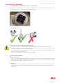
The RVX Series can be mounted as a dome or ball PTZ configuration. To convert the dome to ball PTZ remove the M4
button head screws with 2.5mm allen key provided. See FIG A below.
FIG B MOUNTING ORIENTATION
OBSERVE THE FOLLOWING PRECAUTIONS WHEN INSTALLING:
1. Mount the Camera in a position where it cannot be be interfered with either intentionally or accidentally.
2. The mounting surface should be capable of supporting the weight of both the Camera and mounting brackets under
all expected conditions of load, vibration and temperature.
3. The mounting brackets should be fitted in accordance with instructions and should observe all appropriate safety
precautions & local building regulations.
4. Ensure the Camera is in the correct orientation, see FIG B above.
1.2
ATTACHING CAMERA TO BRACKET
BRACKET INSTALLATION:
Fixings to the various bracket types will depend on the fixing surface. It is important to use adequate quality fixings to
safely support the complete Dome/Ball PTZ assembly. Fixing slots on a 4” PCD provide adequate clearance for 6mm
bolts if attaching the Pedestal or Swan Mount to the mast.
FLYING LEAD:
If using a Swan/Pedestal/Pendant Mount, install the Fly Lead optionally through the Central Mounting Tube or via a
20mm Gland Entry Point. The Gland Entry is supplied with a 20 x 1mm thread to accomodate industry standard
20mm Glands.
1
X-IP-SERIES USER MANUAL
ATTACHING CAMERA TO THE BRACKET: See Fig C & D below
1. Remove Mount Cover Plate.
2. Fully unscrew Hand Lock Nut.
3. Offer Camera to Bracket. The Mounting Boss orientation is important and should match the picture in FIG C & D below.
i.e The Flat Edge should be positioned to the rear and the Retaining Lugs engaged in the Boss Cut Outs.
4. If RV-PED (Pedestal) is being used support the Camera with hand when tightening the Hand Lock Nut - ensure the
Hand Lock Nut is fully tightened.
5. Ensure the Clearance is even throughout 360° rotation and the Camera is free moving.
6. Replace Mount Cover Plates.
1.3
BRACKET TYPES
RV-SWAN (Swan mount), RV-WALL (Wall mount), RV-PNDT (Pendant mount), RV-PED (Pedestal for mast/tower mount).
TECH SUPPORT COMMENT: It is important to configure software settings to the camera orientation
(Basic Configuration > Mounting Orientation) i.e. is the Camera hanging down or upright?
‘hanging down’ would be using one of the following bracket types :
• swan [RV-SWAN] ,
• pendant [RV-PNDT]
• or wall [RV-WALL] - NOT SUITABLE FOR UPRIGHT MOUNTING
‘Upright’ would be using the pedestal bracket [RV-PED]
1.4
2
HOW TO CANTILEVER ARMS FORWARD
1. Remove pear shaped badge on each arm using small flat head screw driver.
2. Slightly loosen by one turn (BUT DO NOT REMOVE) the allen screws.
3. Cantilever the Ball Arms forward to ‘STOP’ position.
4. Tighten allen screws.
5. Replace badges (spares are provided).
6. See Section 6.1.3.1.2 and from the SET UP MENU select either ‘UPRIGHT
ARMS OUT’ or ‘HANGING ARMS OUT’
HOW TO CONFIGURE THE CAMERA INTERFACE
NO HARDWARE CONFIGURATION OF THE CAMERA IS REQUIRED.
ALL OPTIONS ARE SET VIA THE IP INTERFACE WHEN THE CAMERA IS COMMISSIONED.
2
3
X-IP-SERIES USER MANUAL
POWER SUPPLY INSTALLATION & SETUP
WARRANTY & SAFETY NOTICE: DISCONNECT ALL POWER BEFORE
OPENING OR WORKING ON THE POWER SUPPLY UNIT. INSTALLATION
MUST BE CARRIED OUT BY A SUITABLY QUALIFIED PERSON.
Camera Warranty is void unless it is installed using one of the following Redvision power supplies and a Redvision supplied
fly lead (Composite cable): Using the wrong type of 3rd party PSU could compromise safety and damage the camera unit.
• RVX-IP-PSU • RVX-!P-PSU-ALM16 • RVX-IP-PSU-ALM16-W
The RVX Power Supplies are compatible with the following X-Series Cameras:
RVXIP30, RVXIP30-W, RVXIP30-IR, RVXIP30-IR-W, RVXIP30-IRWL, RVXIP30-IRWL-W.
UMBILICAL CABLE: A pre-made composite cable with a 7 way female amphenol connector is supplied with all Redvision
brackets. The female connector connects directly to the male connector on the RVX PTZ IP Camera housing.
• Mount the Redvision PSU in a position so it cannot be interfered with intentionally or accidentally.
Ideally use a lockable cabinet.
• Securely fix the Redvision PSU using appropriate size screws and ensure the cable glands have sufficient
clearance to allow the cables to enter.
• All cables should be channelled through the appropriate sized gland holes.
• Only use Redvision supplied umbilical cables for connecting the X-IP-SERIES ball/PTZ dome & Redvision IP PSU.
Warranty will be void if these cables are extended between the PTZ/dome unit and PSU. Extending cables could
also compromise safety.
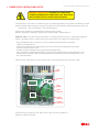
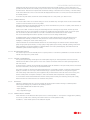
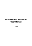
Follow the colour coding idents as shown in table on page 4 for terminating the fly lead in the power supply.
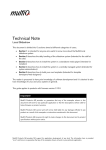
METAL
PLATE
MAINS INPUT
654321
EARTH
TERMINAL
CAMERA
CONNECTION
NETWORK
CONNECTION
4 CORNER
FIXING HOLES
The Redvision power supply (part code: RVX-IP_PSU) outputs 24V DC &is supplied in a
weather proof ABS box rated IP67.
3
X-IP-SERIES USER MANUAL
1
6
5
2
6
3
4
5
4
3
2
1
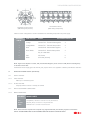
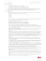
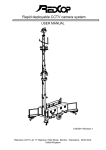
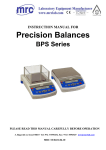
Terminal Block Pinout
(Male mating side pictured)
Amphenol Connector Pinout
(Male mating side pictured)
Follow the colour coding idents as shown in table below for terminating the fly lead in the power supply.
AMPHENOL
PIN NO.
WIRE COLOUR
SIGNAL
PSU CONNECTOR PIN NO.
1
Orange
Camera TxN - Transmit Data negative
3
2
Orange/White
Camera TxP - Transmit Data positive
4
3
Blue
Camera RxN - Receive Data negative
1
4
Blue / White
Camera RxP - Receive Data positive
2
5
-
Key for cable ident.
-
6
Red
24V Power
5
7
Black
0V Power (Ground)
6
NOTE: Signal names depend on context, TxN (Transmit Data Negative) for the camera is RxN (Receive Data Negative)
for the PSU or Alarm Unit.
The Redvision Power Supply (part code: RVX-IP_PSU) outputs 24V DC & is supplied in a weather proof ABS box rated IP67.
3.1
REDVISION IP POWER SUPPLY (RVX-IP-PSU)
3.1.1
SUPPLY VOLTAGE
3.1.1.1
INPUT VOLTAGE
Mains input :110V/230V @ 0.5A
3.1.1.2
OUTPUT VOLTAGE
Output @ Camera connector : 24Vdc @ 3A nominal
3.1.2
RVX-IP-PSU INTERNAL CONNECTIONS
3.1.2.1
MAINS POWER INPUT
PCB IDENT
MAINS POWER
*
LIVE
LIVE (BROWN) 110/230Vac Connection via 2 way terminal block
*
NEUTRAL
NEUTRAL (BLUE) Connection via 2 way terminal block
*
EARTH
GREEN/YELLOW Connection via terminal screw
NOTE: Earth connection requires 4mm red spade loop (supplied with PSU) to be fitted by engineer at installation.
SAFETY: ENSURE MAINS INPUT & EARTH CONNECTIONS ARE SECURELY STRAIN RELIEVED.
4
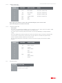
3.1.2.2
X-IP-SERIES USER MANUAL
CAMERA CONNECTION
6 Way Terminal Block
PIN NO.
PCB IDENT
WIRE COLOUR
SIGNAL
1
TxN
Blue / White
PSU TxN / Camera RxN
2
TxP
Blue / White
PSU TxP / Camera RxP
3
RxN
Orange
PSU RxN / Camera TxN
4
RxP
Orange / White
PSU RxP / Camera TxP
5
24V
Red
6
GND
Black
NOTE: Signal names depend on context, TxN (Transmit Data Negative) for the camera is RxN
(Receive Data Negative) for the PSU or Alarm Unit.
3.1.2.3
NETWORK CONNECTION
RJ45 SOCKET
This socket is a typical Ethernet 100BASE-T type, for connection of a 'Cat 5' cable, wired to the T568A or T568B
scheme. The typical wire colours noted below are of the T568B scheme.
The camera supports automatic polarity and automatic crossover (Auto MDI/MDIX) to simplify installation
cabling.
Due to the multiple interconnections required for the PTZ unit and power supply, the maximum specified cable
run from the PSU to network hub or switch is 50m. For longer cable runs, the Alarm PSU (RVX-IP-ALM)
includes a repeater and offers operation up to at least 100m.
The use of high quality Cat5e or Cat6 cable to connect to the network is highly recommended for reliable
operation.
3.1.3
PIN NO.
PCB IDENT
WIRE COLOUR
1
TxP
White / Orange
2
TxN
Orange
3
RxP
White / Green
4
-
Blue
5
-
White / Blue
6
RxN
7
-
White / Brown
8
-
Brown
Green
FUSE PROTECTION
PCB IDENT
* F1
F2
DESCRIPTION
Mains input fuse 3.15A - Anti Surge*
Camera fuse 3.15A - Fast Blow
5
3.2
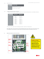
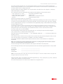
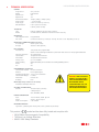
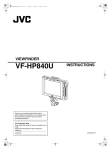
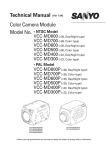
REDVISION IP POWER SUPPLY WITH ALARM MODULE (RVX-IP-PSU-ALM)
WARRANTY & SAFETY NOTICE:
DISCONNECT ALL POWER BEFORE
OPENING OR WORKING ON THE
RVX-PSU-ALM16 POWER SUPPLY
UNIT WITH EMBEDDED ALARM
CARD. THIS PROTECTS HIGH
VOLTAGE COMPONENTS.
INSTALLATION MUST BE CARRIED
OUT BY A SUITABLY QUALIFIED
PERSON.
ALARM/WASH/
AUX RELAY
OUTPUTS
CAMERA
CONNECTION
ALARM
INPUTS
ALARM
CONFIG
SWITCHES
NETWORK
CONNECTION
FIXING
POINTS x4
3.2.1
SUPPLY VOLTAGE
3.2.1.1
INPUT VOLTAGE
Mains input: 110V/230V @ 0.5A
3.2.1.2
OUTPUT VOLTAGE
Output @ Camera connector: 24Vdc @ 3A nominal
3.2.2
RVX-IP-PSU-ALM INTERNAL CONNECTIONS
3.2.2.1
MAINS POWER INPUT
PCB IDENT
X-IP-SERIES USER MANUAL
MAINS POWER
*
LIVE
LIVE (BROWN) 110/230Vac Connection via 2 way terminal block
*
NEUTRAL
NEUTRAL (BLUE) Connection via 2 way terminal block
*
EARTH
GREEN/YELLOW Connection via terminal screw
NOTE: Earth connection requires 4mm red spade loop (supplied with PSU) to be fitted by engineer at installation.
SAFETY: ENSURE MAINS INPUT & EARTH CONNECTIONS ARE SECURELY STRAIN RELIEVED.
3.2.2.2
CAMERA CONNECTION
6 Way Terminal Block
PIN NO.
PCB IDENT
WIRE COLOUR
SIGNAL
1
TxN
Blue
PSU TxN / Camera RxN
2
TxP
Blue / White
PSU TxP / Camera RxP
3
RxN
Orange
PSU RxN / Camera TxN
4
RxP
Orange / White
PSU RxP / Camera TxP
5
24V
Red
6
GND
Black
NOTE: Signal names depend on context, TxN (Transmit Data Negative) for the camera is RxN
(Receive Data Negative) for the PSU or Alarm Unit.
6
3.2.2.3
X-IP-SERIES USER MANUAL
NETWORK CONNECTION
RJ45 SOCKET
This socket is a typical Ethernet 100BASE-T type, for connection of a 'Cat 5' cable, wired to the T568A or T568B scheme.
The typical wire colours noted below are of the T568B scheme.
The camera supports automatic polarity and automatic crossover (Auto MDI/MDIX) to simplify installation cabling.
The Alarm PSU includes an active Ethernet repeater, consequently the maximum specified cable run from the PSU to
network hub or switch is 100m.
The use of high quality Cat5e cable to connect to the network is highly recommended for reliable operation.
3.2.2.4
PIN NO.
PCB IDENT
WIRE COLOUR
1
TxP
White / Orange
2
TxN
Orange
3
RxP
White / Green
4
-
Blue
5
-
White / Blue
6
RxN
7
-
White / Brown
8
-
Brown
Green
ALARM INPUTS
Four 8 Way screw terminal block connectors.
Terminal No.
1
2
3
4
5
6
7
8
P19
P18
P17
P16
Alarm 1 Signal
Alarm 1 Ground
Alarm 2 Signal
Alarm 2 Ground
Alarm 5 Signal
Alarm 5 Ground
Alarm 6 Signal
Alarm 6 Ground
Alarm 9 Signal
Alarm 9 Ground
Alarm 10 Signal
Alarm 10 Ground
Alarm 13 Signal
Alarm 13 Ground
Alarm 14 Signal
Alarm 14 Ground
Alarm 3 Signal
Alarm 3 Ground
Alarm 4 Signal
Alarm 4 Ground
Alarm 7 Signal
Alarm 7 Ground
Alarm 8 Signal
Alarm 8 Ground
Alarm 11 Signal
Alarm 11 Ground
Alarm 12 Signal
Alarm 12 Ground
Alarm 15 Signal
Alarm 15 Ground
Alarm 16 Signal
Alarm 16 Ground
All alarm inputs are 'volt free' and MUST NOT be connected to any powered contacts. Permanent damage may result from
failure to correctly connect the alarm inputs.
NOTE: The 'Alarm xx Ground' connections are all common on the PCB and connected to the PSU ground.
3.2.2.5
AUXILIARY OUTPUTS
Three sets of NO/NCAuxiliary Output contacts are provided (ALARM / AUX / WASH). Each set of contacts are isolated, and
useable for any circuit within the following limitations:Rated load
Max. carrying current
Max. switching Current
Max. switching Power
Contact Resistance
:
:
:
:
:
0.5A @ 125 Vac / 1.0A @ 24Vdc Resistive
2A
1A
62.5VA, 30W
100mOhm max.
ALARM contacts are operated whenever any alarm signal is active.
WASH contacts are operated under operator control for camera lens washing.
AUX contacts are configurable in the camera setup to operate under various scenarios.
7
X-IP-SERIES USER MANUAL
3.2.3
FUSE PROTECTION
PCB IDENT
* F1
Mains input fuse 3.15A - Anti Surge*
F2
3.2.4
DESCRIPTION
Camera fuse 3.15A - Fast Blow
ALARM CONFIGURATION SWITCH SETTINGS
Switches S1 & S2 are used to configure each alarm input channel as Normally Open (N.O.) or Normally Closed (N.C.)
POSITION
1
2
3
4
5
6
7
8
SWITCH S1
SWITCH S2
Alarm 1
Alarm 2
Alarm 3
Alarm 4
Alarm 5
Alarm 6
Alarm 7
Alarm 8
Alarm 9
Alarm 10
Alarm 11
Alarm 12
Alarm 13
Alarm 14
Alarm 15
Alarm 16
In each case, set the switch to ON for Normally Open operation, and OFF for Normally Closed.
NOTE: Where fitted, it may be necessary to remove the Wireless add-on card in order to gain access to the S2 switch
for configuration. Ensure that power is disconnected from the PSU module before removing the wireless card.
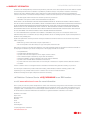
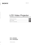
3.3
WIRELESS ALARM PSU (RVX-IP-PSU-ALM-W)
ALARM/WASH/
AUX RELAY
OUTPUTS
CAMERA
CONNECTION
NETWORK
CONNECTION
WIRELESS
CARD
ALARM
INPUTS
ALARM
CONFIG
SWITCHES
WARRANTY & SAFETY NOTICE:
DISCONNECT ALL POWER
BEFORE OPENING OR WORKING
ON THE RVX-PSU-ALM16
POWER SUPPLY UNIT WITH
EMBEDDED ALARM CARD.
THIS PROTECTS HIGH VOLTAGE
COMPONENTS. INSTALLATION
MUST BE CARRIED OUT BY A
SUITABLY QUALIFIED PERSON.
FIXING
POINTS x4
8
X-IP-SERIES USER MANUAL
The Redvision Wireless Card is compatible with the Redvision Wireless PIR, Luminite Genesis Range and the Redwall
Wireless Transmitter Module Part Code WF434T, (wireless enabled Redwall PIRs).
For the main specification and connection information for the WIRELESS ALARM PSU (RVX-IP-PSU-ALM-W), refer to
diagram. This section deals with the additional functions of the Wireless module.
3.3.1
RVX-IP-PSU-ALM-W INTERNAL CONNECTIONS (ADDITIONAL)
3.3.1.1
ANTENNA CONNECTOR
BNC Connector, 50Ohm type
3.3.2
CONFIGURING WIRELESS ALARM MODULE
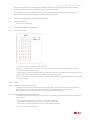
3.3.2.1
DIP SWITCH SETTINGS
SW1
4
1
2
3
4
5
6
7
8
9
10
11
12
13
14
15
16
5
6
7
s
s
s
s
s
s
s
t
s
s
s
8
s
s
t
s
s
s
s
t
t
s
s
t
s
t
s
s
s
s
s
s
s
s
s
s
s
s
s
s
t
t
t
t
t
s
t
t
s
s
s
t
t
s
s
t
s
t
s
s
t
s
t
s
t
t
t
s
s
t
t
t
s
t
t
t
t
s
t
UP
= s
DOWN = t
t
t
• 1 to 3 dip switches are not used & should be left ‘ON’
• Switches 4 to 8 (Dome Head Site Code) provide up to 32 (1 to 16 shown in the table above) channels of wireless
transmission to enable alarm activation.
• The transmission needs to be matched between the Dome Head Site Code on the wireless alarm module & the Site Code
within the PIR detector (see separate PIR installation guide supplied with the PIR).
• One or more domes wil respond to any wireless PIR within range providing the Dome Head Site Code & corresponding
PIR Site Code match.
3.3.2.2
AERIAL
3.3.2.2.1 POSITIONING OF RVX-IP-PSU-ALM16-W
To maximise the transmission range install the PSU externally with the aerial pointing through the gland towards the
ground. An optional booster aerial (RV-AE434) can be used to significantly improve signal and range. It is
recommended to use the booster aerial if the PIRs are installed on metal clad buildings.
3.3.2.2.2 RETRO FITTING WIRELESS ALARM RECEIVER
If retrofitting a wireless alarm receiver card onto an existing 16 way alarm module (RVX-IP-PSU-ALM16-W) observe the
following steps:
• ISOLATE POWER FROM PSU - you cannot hot swap wireless alarm module.
• Align Wireless Alarm Module with P3 Connector and secure with M3 fixings.
• Thread aerial antenna through gland and connect to BNC on Wireless Receiver.
• See Table 19, for DIP switch settings.
9
4
X-IP-SERIES USER MANUAL
CAMERA SETUP
Initial setup of the camera is most easily performed via the web interface, using a direct connection from a PC to the RJ45
socket in the power supply module. The camera may also be configured over the installation network.
4.1
CONNECTING TO THE CAMERA
4.1.1
DIRECT CABLE CONNECTION
This method of connecting to the camera uses a default connection address, called the Link Local IP Address. This
connection is independent of any user configuration that has been done, and should always allow the installer to contact
a camera by direct connection, regardless of any previous changes made to the system.
The required Local Link IP Address can be determined from the device serial number or the MAC address of the camera
(which should both be noted on the camera paperwork or packaging). Alternatively, a 'discovery tool' is available to find
connection parameters for unknown or misconfigured devices.
Calculate the Local Link IP address as follows :IP = 169 . 254 . xxx . yyy
where
yyy = 1 + (serial number mod 128)
xxx = 1 + ((serial number divided by 128) mod 128)
e.g.
Serial Number = 123456
123456 / 128 = 964 remainder 64
so yyy = 65
964 / 128 = 7 remainder 68
so xxx = 69
Local Link IP Address = 169.254.69.65
NOTE: The Redvision IP Camera Discovery Tool can be used to calculate Local Link default addresses from a camera
MAC address or Serial Number. OTHER THIRD PARTY DOWNLOADS ARE AVAILABLE, SUCH AS ‘ANGRY IP’:
http://www.angryip.org/download
Connect the PC Wired LAN port directly to the RJ45 socket in the PSU, using a Cat5/5e patch lead. This can be either a
'direct' or 'crossover' type cable. Set the network configuration of the PC to the following values :IP Address
: 169.254.1.254
Network Mask : 255.255.0.0
: 169.254.1.254
Gateway
(Broadcast)
WINS (pri)
WINS (sec)
DNS (pri)
DNS (sec)
:
:
:
:
Not Required
Not Required
Not Required
Not Required
Power up the camera, and wait at least 2 minutes before attempting to configure the camera.
4.1.2
LAN CONNECTION USING LOCAL NETWORK WITH DHCP SERVER.
A factory-fresh dome is preconfigured to attempt to obtain a suitable network address and configuration from a network
DHCP server.
Connect the RJ45 socket in the PSU to a network LAN port, using a Cat5/5e patch lead. This can be either a 'direct' or
'crossover' type cable. Camera initial configuration should be automatic.
The connection address of the camera may be found by interrogating the DHCP server (consult local IT support staff) or
by use of the Redvision IP Camera Discovery Tool run on a Windows based PC on the local network.
Power up the camera, and wait at least 2 minutes before attempting to configure the camera.
10
X-IP-SERIES USER MANUAL
4.1.3
LAN CONNECTION WITHOUT LOCAL DHCP SERVER
Due to the large number of variations possible in the network structure, it is difficult to predict if the camera will be
contactable using the Local Link IP address in a given network. The simplest solution in this case is to use the 'Direct
Cable Connection' method below to configure the camera for a fixed IP address in a useable range (consult local IT
support) before connecting the camera directly to the local network.
4.1.4
DIRECT CABLE CONNECTION WITH DHCP
If required, it is possible to operate a standalone DHCP server on a computer used for camera configuration, as an
alternative to using the Link Local addressing scheme. Various DHCP server software is available for different operating
systems. For Windows based PCs, one suitable free option is “DHCP Server for Windows” from
http://www.dhcpserver.de/ . No specific setup help can be offered here as each software will be different, but usually
setting a 'pool' range of only 1 address will mean any camera connected will be assigned the same address.
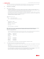
4.2
CAMERA CONFIGURATION VIA WEB INTERFACE
Note : Most javascript capable web browsers are supported for operation of the camera. Most testing is carried out
using Firefox, but any mainstream browser should be suitable (Microsoft Internet Explorer, Google Chrome etc.).
To view video streams in the web browser, it may be necessary to install additional software. Consult 'Web Browser
Configuration' in the Appendix of this document.
Open a web browser on a connected PC or other web-enabled device, and in the address bar enter the IP address as
determined above :- e.g. http://192.168.2.1
After a short delay, the entry web page of the camera should appear.
Select 'Admin functions' > 'Networking configuration'.
(Administrator level login privileges will be required for access, the default admin account is Username 'admin',
password '9999')
11
X-IP-SERIES USER MANUAL
Enter the required network configuration information, or select 'Enable DHCP' as required. Note that once 'SAVE' is
clicked to store the required configuration, the network interface will be reset and the setting will be changed as
programmed. Change the network connection to the camera if required (i.e. if on a direct cable connection, but setting
the camera for a DHCP network, change the network cabling over and if necessary power cycle the camera)
The camera should now be contactable via the network as configured.
4.3
User Account Configuration
User accounts should be configured for all authorised camera users who will have access to the web interface.
AS A MINIMUM THE PASSWORD FOR THE 'ADMIN' USER SHOULD BE CHANGED FROM THE DEFAULT VALUE.
Accounts can be created and edited from the 'Admin functions > User Accounts and Permission' page.
Three levels of access privilege are provided for accounts.
5
Viewer:
Can access live video streams only
Operator:
Can access all camera control functions
Administrator:
Can access all configuration pages
CAMERA OPERATION
Initial setup of the camera is most easily performed via the web interface, using a direct connection from a PC to the RJ45
socket in the power supply module. The camera may also be configured over the installation network.
5.1
OPERATION VIA WEB INTERFACE
The web interface provides the default method for setting all the main camera operational values, as well as a basic
control system and video stream viewer. Using a javascript capable web browser, connect to the configured IP address
as for the initial configuration.
5.2
OPERATION VIA CGI COMMAND
The RVX-IP dome will accept control via the network in the form of Common Gateway Interface queries. This is
intended for use by third party devices to provide a dedicated interface channel. Consult Redvision CCTV for further
information and the proprietary software development kit.
5.3
OPERATION VIA ONVIF INTERFACE.
ONVIF (Open Network Video Interface Forum – www.onvif.org) provides a standardised interface for interworking of
devices from different manufacturers.
The RVX-IP dome is intended to be compliant to ONVIF Profile S as a Network Video Transmitter, and should be
controllable by any Profile S compliant client device.
The ONVIF interface is enabled and discoverable on the local network by default. Consult the documentation for the
client device for procedure for discovering and enabling NVT (Network Video Transmitter) hardware.
12
6
WEB INTERFACE
X-IP-SERIES USER MANUAL
The layout of functions in the web interface is as follows :• Home
• Camera
View Camera
Live Streaming
Controls
Configure camera
Preset Positions
Edit Presets
Patrol Tours
Edit Tours
• Alarms
View Alarms
Live Alarms
Enable Live Update
Update Interval
Configure Alarms
Alarm Board
Wireless Alarms
Configure Camera
Basic config
Camera Profiles
Profile 1
Profile 2
Profile 3
Profile 4
Profile 5
Video Streaming profiles
Admin Functions
Networking configuration
User accounts & permissions
Add Users
Edit/Remove Users
Maintenance
6.1
HOME
6.1.1
CAMERA
This section contains the functions related to the normal operation of the camera, view video streams, PTZ control etc.
6.1.1.1
VIEW CAMERA
6.1.1.1.1 LIVE STREAMING
6.1.1.1.1.1 STREAMING OFF
Stop displaying video streams in the web interface.
6.1.1.1.1.2 PLAY STREAM 1
Shows the video stream from the camera primary output, along with connection information for use in other equipment
or software.
6.1.1.1.1.3 PLAY STREAM 2
Shows the video stream from the camera secondary output, along with connection information for use in other
equipment or software. This menu will only be visible if the camera is configured to generate 2 or more video streams.
6.1.1.1.1.4 PLAY STREAM 3
Shows the video stream from the camera tertiary output, along with connection information for use in other equipment
or software. This menu will only be visible if the camera is configured to generate 3 video streams.
13
6.1.1.1.2
CONTROLS POPUP
Open a floating controls window for PTZ control of the camera.
6.1.1.1.3
CONFIGURE CAMERA
6.1.1.2
PRESET POSITIONS
X-IP-SERIES USER MANUAL
6.1.1.2.1 EDIT PRESETS
Edit preset information for selected preset
6.1.1.3
PATROL TOURS
6.1.1.3.1 TOUR N
Run or Edit tour configurations.
6.1.2
ALARMS
6.1.2.1
VIEW ALARMS
6.1.2.1.1
LIVE ALARMS
View live alarm status messages
6.1.2.1.1.1 UPDATE INTERVAL
Change the rate at which the web interface checks the alarm status.
6.1.2.1.2 CONFIGURE ALARMS
6.1.2.1.2.1 ALARM BOARD
Edit configuration of individual alarm channels, where fitted.
6.1.2.1.2.2 WIRELESS ALARMS
Edit configuration of individual wireless (PIR) alarm channels, where fitted.
6.1.3
CONFIGURE CAMERA
6.1.3.1
BASIC CONFIG
[25/50 – 30/60 Setting]
6.1.3.1.1 CAMERA TITLE
This is a simple title for the camera, making it easier to identify the correct camera in multi unit installations.
6.1.3.1.2 MOUNTING ORIENTATION
Defines the mounting arrangement for the camera. This will affect the output video picture and pan/tilt movement
direction of the camera.
6.1.3.1.3 INSTALLATION NOTES
Allows the installer to include any short note relating to the camera installation, such as exact location, cable
identification etc.
6.1.3.1.4 TIME & DATE SETTING
It is important that the camera time and date are correctly set. A camera reporting incorrect date and time information
may be rejected by a NVR or controller for security reasons.
Time and date may be automatically set from a network time server, called an NTP Server, either on the local network or
accessed via the internet if a connection is available. This process may be scheduled to run only at power-up, or
automatically once per day to ensure continued accuracy. The Server Address must be correctly set for this process to
succeed.
HINT: For security reasons, the preferred option would be to connect to a local timeserver on the network. Consult your
network manager for connection information. In the event that a local network timeserver is not available, then a public
timeserver on the internet may be used if the local network configuration allows it.
Likely addresses would be uk.pool.ntp.org for UK installed cameras or more generally pool.ntp.org, either of which will
return a connection to a randomly assigned time server located in, or close to, the installation country.
14
X-IP-SERIES USER MANUAL
Setting time and date via an NTP server is the preferred option where possible. However, in cases where this is not
possible, time and date must be manually set up.on each camera. This may be done quickly set from the device running
the web browser. Note that it is important that the timezone settings of this device are set correctly, or the time setting
in the camera will not be correct. In the event that the displayed browser time is not correct, then the time and date can
be manually entered.
In the event of power failure, the RVX-IP camera will keep time for a short period, up to about 4 hours.
6.1.3.1.5 CAMERA PROFILES
This section selects which set of camera settings to use for the default 'day' and 'night' mode. See the 'Camera Profiles'
section for more information on the use of profiles.
Day Night switching may be performed manually, e.g. via the web interface or by the use of 'special' preset selection, or
according to the camera metered light level.
There are two 'slider' controls for setting the metered light level for switching into night mode, and into day mode.
If these values are set too close together, the camera may toggle back and forth between modes. If set too far apart,
then the camera may become locked into one mode or the other if the threshold value is never reached.
The current metered light level value is reported on screen to assist in setting suitable values.
An additional slider control 'Switching Delay' sets the time for which the light level must be maintained over the
threshold before switching is carried out. This prevents the camera mode from being changed by passing car
headlights, or looking into a dark corridor during a tour.
Capture Framerate sets the video timebase selection for the camera imager. The selection choice is between 30fps
(60fps in high speed capture modes), or 25fps (50fps in high speed capture modes). Generally speaking, 25/50 mode
will be preferably in European installations to eliminate flicker from mains powered lighting, and 30/60 mode in US
installations (where the mains frequency is 60Hz).
6.1.3.1.6 RESTORE/HOME POSITION
The camera may be set to automatically return to a preset position or commence a predefined tour, if there has been no
manual control input for a period of time.
6.1.3.1.7 CONTROL CONFIGURATION
The Joystick Speed Scaling control adjusts the overall speed range for pan and tilt operations, both from the web
interface and via ONVIF control systems. This is most useful for onvif clients which don't offer speed adjsutment for
their PTZ controls.
If 'Datum Check' is selected, the camera will automatically check the calibration of the pan and tilt position, and exercise
the motor mechanisms, once per day at a pre-determined time.
This option is useful for cameras where external disturbance is occasionally a problem, or where the camera operates
largely on automatic tour over only a small movement range, to prevent uneven wear occurring in the long term.
PTZ Power Saving mode reduces the power supplied to the pan and tilt motors when the camera is not moving. This
reduces overall power consumption and helps to reduce the internal camera temperature to improve reliability.
In circumstances where external interference with the camera position is likely, then switching off the power saving
feature increases the camera resistance to movement when parked.
6.1.3.2
SHORTCUTS
Selecting a numbered preset as a shortcut activates the named function instead of moving to a defined position.
Shortcut preset settings are provided for the following functions:• Wash (Only available with the Alarm PSU option)
• Wiper (if fitted)
• Day / Night Mode Toggle
6.1.3.2.1 CAMERA PROFILE OVERRIDE
Preset memories can be selected to allow quick access to camera profiles 1-5. Each preset is a toggle action (selecting
once forces a profile switch, selecting a second time returns to normal operation mode).
In addition, a 'Cancel Profile' preset can be selected if required.
15
6.1.3.3
CAMERA PROFILES
X-IP-SERIES USER MANUAL
6.1.3.3.1 BASE FEATURES
These features are applied globally to all camera profiles.
• Invert Image – Flip the output video images vertically (Top to Bottom)
• Mirror Image – Flip the output video images horizontally (Left to Right)
NOTE: These settings are usually only used in special circumstances. Before using these settings, ensure that the
installation setting Configure Camera > Basic Config > Orientation has beencorrectly specified.
6.1.3.3.2 CAMERA PROFILE
There are five different camera profiles available to the user. Each can be set to optimise the camera performance for a
particular situation. By default the profiles are named as follows :•
•
•
•
•
Daytime
Indoors
Low-Light
Zero-Light
User
The factory default settings for each profile are pre-set to give broadly the best performance in each situation, but each
can be renamed and modified to suit individual customer requirements.
For each profile, the following settings exist :•
•
•
•
•
•
•
•
•
•
•
•
•
•
•
•
•
•
•
Profile Name – The profile name can be changed to indicate intended use.
Profile Default – Reset the individual profile to factory default settings
Lamp Mode – Select OFF / IR / WHITE lamp operation (model dependant)
Auto Focus (Joystick) – Select if the camera should auto focus when operating under joystick control.
Auto Focus (Preset/Tour) – Select if the camera should auto focus after moving to a preset, or moving to each preset
stage of a tour. The camera will always move to the stored focus position as each stage, but then remian in manual
focus or return to automatic focussing.
Backlight Compensation – Improves visible detail by compensating for the dark exposure produced when viewing an
object against a brightly lit background field.
Digital Zoom – Allows the optical zoom lens to be supplemented by cropping the picture to produce apparent
additional zoom.
IR Cut Filter – In 'Visible Light' mode, the IR Cut filter prevents infra red light from reaching the lens, producing a full
colour, sharply focussed image. In 'IR Light' mode, the camera produces a monochrome image from all available
light, both visible and infra-red. This is the most sensitive mode for the camera, and is usually used with IR lamps.
IR Focus Correction – When operating in IR mode, if there is significant visible light present, the image produced may
appear out of focus. This is caused by the lens focussing IR light slightly differently to visible light. IR Focus
Correction sets the camera focussing to be correct for either Visible Light or for IR Light, according to user
preference.
Image Stabiliser – When ON, the camera applies full time digital processing to the output video, to remove shake
caused by small camera movements (e.g. in windy locations). This setting is disabled when the camera is moving,
and re-enabled when stopped.
Spot AE Metering – If ON, the image exposure is calculated from the centre of the picture only (to produce best detail
of the object of interest in a manually controlled camera). If OFF, the exposure calculation uses the entire image
(producing the best average image on an automatically touring camera).
AE Mode – In 'AUTO' mode, the camera exposure is calculated for the best overall compromise between the various
settings (Shutter Speed / Aperture / Gain). In 'Shutter Speed Priority' mode, the camera will hold on to the specified
shutter speed as long as possible by adjusting the Aperture and Gain settings first. This is useful where a high shutter
speed is desirable (fast moving targets) at the cost of a more grainy image in low light conditions.
Shutter – Select the preferred shutter speed when 'AE Mode' is set to 'Shutter Speed Priority'.
AF Sensitivity – In 'LOW' sensitivity mode, the camera requires a larger focus error before triggering an auto-focus
action – this prevents the camera from continuously refocussing ('focus hunting') in certain situations.
Aperture (Edge/Sharpness Enhance) – Select the degree of edge enhancement (sharpness) the camera applies to the
video image.
Defog – When selected, tries to compensate for fog or mist in the camera image by digital post processing.
Exposure Compensation – Adjust the default exposure setting of the camera to lighten or darken the typical image
produced. A range of -7 to +7 'stops' is allowed. One 'stop' represents one step in the shutter speed, or lens aperture
setting.
Gamma – Selects the colour compensation curve used by the camera, between 'Standard' and 'Straight' curves.
High Res – Set the video output to enhance the fine detail contained.
16
X-IP-SERIES USER MANUAL
• High Sensitivity – Setup the camera to give the highest light sensitivity possible, may produce a more grainy picture.
• Noise Reduction – when selected, the output video is processed to remove speckling and noise under low light
conditions. The setting may be applied differently in moving and parked situations.
• White Bal – Adjusts the colour palette of the video picture to suit different lighting conditions. Auto Tracing modes
will automatically compensate for changing lighting levels.
• Colour/Mono Effect – Sets the output video picture to colour or monochrome. This is only effective when IR Cut Filter
is set to 'Visible Light' mode. It has no effect when operating the camera in infra-red mode.
• Crosshair – Applies a 'gunsight' crosshair to the output video image.
6.1.3.4
VIDEO STREAMING PROFILES
Set up the camera streaming settings to suit operational requirements. Up to three streams may be generated in various
resolutions and formats. Due to hardware limitations, not all combinations of encoder type and image size are available.
Output bandwidths for each stream may be adjusted individually to suit quality and network requirements.
Stream 1 bandwidth may be adjusted between 500kbps and 8000kbps
Streams 2/3 may be adjusted between 64kbps and 4000kbps
In MJPEG streams, bandwidth selection is accomplished by selecting a target image quality, in the range 5 – 98%
The RTSP port numbers for each stream may be changed from the camera default if required. This is most useful for
clients which expect a primary RTSP stream on port 554. The port numbers selected will be reflected in the stream URI
links provided via the web interface, and via the ONVIF control interface. A system reboot will be required.
Note : Each stream number must be unique. The RVX-IP dome does not currently support composite streams supplying
multiple video channels within a single stream.
The default port numbers as delivered are 8557 for Stream 1, 8555 for Stream 2, and 8556 for Stream 3.
6.1.4
ADMIN FUNCTIONS
6.1.4.1
NETWORKING CONFIGURATION
Set the network configuration to suit the local installation requirements. Be aware that choosing invalid settings here
may render the camera unuseable until re-configured locally.
6.1.4.2
USER ACCOUNTS & PERMISSIONS
6.1.4.2.1 ADD USERS
Create new user logins for camera, with various levels of authority.
6.1.4.2.2 EDIT/REMOVE USERS
Edit or delete existing camera user accounts.
6.1.4.3
MAINTENANCE
The Maintenance menu includes tools to reset various camera configurations.
6.1.4.3.1 REBOOT CAMERA
Restarts the main camera software from a 'power on' state. This may be useful if the camera behaviour is inccorect
after a configuration change.
6.1.4.3.2 RESET ONVIF PROFILES
Some DVR's and controllers can set conflicting configurations in ONVIF profiles This option returns the ONVIF camera
profile configurations to their default settings. A reboot operation will be required after using this option.
6.1.4.3.3 RUN DATUM NOW
This allows the operator to force the camera to carry out a datum check, and exercise the mechanism through a full
range of movements. Upon completion of datum check, the status for Pan and Tilt axis movement is displayed, and the
dome will return to the last parked position. (This may take up to 60 seconds once the datum check is complete).
6.1.4.3.4 RESET TO DEFAULTS
Reset all user configurations to factory default settings. Network settings and user logins/passords are all reset. A
reboot is required to complete the operation.
6.1.4.3.5 FIRMWARE UPGRADE
Note that firmware upgrade via the web interface requires that port 8080 be accessible on the camera. This may require
firewall settings to be changed on the user network.
HINT: Firmware upgrade option appears in the left hand menu box once 'Maintenance' has been selected.
17
X-IP-SERIES USER MANUAL
This option should be used with care, since if improperly carried out, the camera may be rendered inoperable and
require servicing by Redvision CCTV to restore operation. Also note that for in-service cameras, stored information such
as Preset positions and Tour settings may be lost.
Firmware upgrades are usually supplied as '.zip' compressed files. These files need to be 'unzipped' to a temporary
folder before upload to the camera.
Each .zip file will contain the following files (exact filenames will be different for each firmware version) :•
•
•
•
rvxip_fs_B03f_2014_10_22.bin
rvxip_fs_B03f_2014_10_22.bin.sfv
release_notes_RXVIP_B03f.pdf
gfsw.exe
-
the firmware upgrade binary image
Checksum file
Release notes for the firmware versions
Simple file integrity checker
(http://esrg.sourceforge.net/utils_win_up/md5sum/)
Where possible, the firmware upgrade image should be checked before uploading to the camera. Various software such
as anti-virus tools and email firewall can corrupt binary image files. The checksum file contains a key value, calculated
from an original image file. If the key is re-calculated from the supplied binary image, it will be different if the image file
has been modified in any way.
From Windows Explorer, browse to the temporary folder containing the unzipped files. Open the checksum file (e.g.
rvxip_fs_B03f_2014_10_22.bin.sfv) with a text editor such as Windows Notepad. The file contains a single line of text,
listing the file name of the firmware image, and a hexadecimal number as a check. Note the checksum value.
e.g. rvxip_fs_B03f_2014_10_22.bin e4e08827
Run the file integrity checker program gfsw.exe (double click on it), then drag and drop the firmware image file
(rvxip_fs_B03f_2014_10_22.bin) onto the message window.
After a few seconds, the window will display '–----- FILE SIGNATURE COMPLETE --------'. Just above this will be a line
beginning “CRC-32:”.
If the checksum value on this line as the one read from the checksum file, then the binary image file is intact. (For this
check, the case of letters is not important, so 'e4e08827' is the same as 'E4E08827'
If the number calculated is different, DO NOT upload the file to the camera, contact Redvision for a replacement
upgrade file.
NOTE: It is not necessary to use the supplied gfsw.exe program, any utility program which calculates a CRC-32
value for a file should produce the same checksum value.
From the home page of the camera web interface, select 'Support Information in the centre panel'.
Note the following information, which may be required in the event that a firmware upgrade introduces a new problem.
Kernel Build
Encoder Build
PTZ Build
Serial Number
:
:
:
:
_______________________________________
_______________________________________
_______________________________________
_______________________________________
HINT: In the Firefox web browser, simply 'right click' and select 'Save Page As' to record the complete contents of the page. Give
the page a unique name, and save as '.htm' file.
Select the 'Browse' button, and navigate to the firmware upgrade file (e.g. “rvxip_fs_B03f_2014_10_22.bin”). Select the
'Upload' option and follow on-screen instructions.
The camera will prompt the user to reboot at the completion of the upgrade process.
18
7
WEB INTERFACE CONFIGURATION
X-IP-SERIES USER MANUAL
Any modern, standards compliant web browser is suitable for carrying out basic configuration of the RVX-IP Camera. It may
be necessary to install additional software tools to gain full functionality. The preferred web browser software is Mozilla
Firefox, version 32.0.1 or later.
7.1
JAVASCRIPT
Javascript must be enabled to obtain full functionality. In Firefox, the support for Javascript is enabled by default. If the
camera web pages report 'Please enable Javascript' then support has been intentionally disabled in some way.
Caution : The following procedure, if carried out incorrectly, may prevent Firefox from working correctly. Follow the
instructions carefully.
In the address bar of Firefox, enter:
about:config
Read and inwardly digest the dire warnings, then click “I'll be careful, I promise!”.
In the Search bar at the top of the page, enter:
javascript.enabled
In the short list that results, for the item 'javascript.enabled', ensure the 'value' field is set to 'true'. If it is set to 'false',
then double click on the field to toggle its value.
Close the page and return to the web interface. If the web interface is still requesting javascript support, then the wbe
page is most likely being blocked an 'add-on' security tool such as NoScript. From the 'Tools' menu item, select 'Addons', then check the list of additions under 'Extensions' and 'Plugins' for any tools which block javascript actions, and
adjust the settings as required.
7.2
VIDEO STREAMING PLUGIN
In order to view the live video streams embedded in the web browser, Redvision CCTV uses 'VLC media player', a free,
open source media player which is available for most common systems at http://videolan.org
Download and install the media player application for your system type.
For best performance, follow these instructions :Run the VLC media player application.
Select Tools > Preferences from the menu bar.
In the 'Advanced Preferences' popup, under 'Show settings', select 'All'
Select 'Input / Codecs', scroll down the list to 'Advanced'.
Set the following values :Network Caching = 300
Click 'Save' then close the application.
HINT: this value reduces the video latency – the time delay between live action and displayed video. It can be reduced further, but
video 'breakup' becomes more likely, or increased to improve displayed video quality. 250 mSec is a sensible minimum value, and
there is little or no benefit increasing the value past 1000 mSec.
In Firefox, select Tools > Add-ons from the menu bar. In the search box, enter VLC, then select 'VLC Web Plugin' and
install it.
At this point, direct the web browser to the camera web interface and select Camera > ViewCamera > Live Streaming >
Play Stream 1 This should display the camera live video after a short delay.
At the bottom of the page, selecting the link address following 'Main Stream RTSP Link:' should launch the standalone
VLC media player and display the live video feed. If instead, a message similar to 'Firefox does not know how to open
RTSP files' is displayed, then follow these steps :In the address bar of Firefox, enter
about:config
Read and inwardly digest the dire warnings, then click “I'll be careful, I promise!”.
In the list view, right click and select New > Boolean
For 'Preference Name' enter 'network.protocol-handler.expose.rtsp' and set the value to 'False'
Close the page, and return to the camera live streaming page.
Click on the RTSP link again, Firefox should launch a 'Launch Application' dialog. Click 'Choose', and navigate to the
VLC Media Player application. This is probably located at 'Computer > Local Disk (C:) > Program Files (x86) > VideoLAN
> VLC' and called 'vlc.exe'.
19
X-IP-SERIES USER MANUAL
Click 'Open', then tick the box 'Remember my choice for rtsp links.', then click 'OK'.
Retry the RTSP link if necessary, Firefox should now open the VLC standalone player.
In some cases the above procedure will not work on PCs running Windows. In this case, it may be necessary to add a
'key' to the Windows Registry to indicate the required action. Some hints are provided at “Making Windows handle
RTSP URLs” at the NCSA IT Services wiki.
(https://wiki.ncsa.illinois.edu/display/ITS/Making+Windows+handle+RTSP+URLs).
In short, create a file in Notepad, containing the following text:Windows Registry Editor Version 5.00
[HKEY_CLASSES_ROOT\rtsp]
@="Real Time Streaming Protocol"
"URL Protocol"=""
[HKEY_CLASSES_ROOT\rtsp\shell]
[HKEY_CLASSES_ROOT\rtsp\shell\open]
[HKEY_CLASSES_ROOT\rtsp\shell\open\command]
@="\"C:\\Program Files\\VideoLan\\VLC\\vlc.exe\"%1"
Save the file as 'rtsp.reg' and save it on the desktop. Double click the icon and follow the instructions to add it to the
Windows Registry. This should then allow the web browser to correctly handle RTSP video links.
20
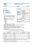
8
TECHNICAL SPECIFICATION
CAMERA
Image sensor
Model
Optical zoom
Digital zoom
Horizontal resolution
Angle of view
Focal Length
Min illumination
X-IP-SERIES USER MANUAL
Sony 1/3" CCD
FCB-EH7500
30x
12x
1920px (1080p) / 1280px (720p)
~ 2.3 to 63.7deg.
4.3mm to 129mm (f1.6 to f4.7)
0.35 lx (1/30 sec ICR OFF)
0.002lx (1/4sec ICR ON)
TELEMETRY
LAN
RS485
Ethernet 100BaseT via Cat5, RJ45 connector
Via LAN ethernet, dedicated connection for Alarm unit only.
MECHANICAL
Left & Right Pan Limit
Pan & Tilt
Programmable
Continuous 360 Pan (0.1-200 per second). Tilt +60° to -90° depending on set up.
INFRA RED ILLUMINATION (RVX-IR versions)
IR wavelength
850nm (semi covert)
IR range
Tested to 100m (850nm)
KEY FEATURES
Presets/Tours
Password protection
Camera titles
Preset titles
Privacy zones
Alarm handling
Heater
Fan
100 presets with programmable
940nm covert wavelength available to special order titles & 8 tours with programmable titles
Yes (three levels)
16 alphanumeric characters
16 alphanumeric characters
up to 16 available.
Weekend/weekday time schedules for enabling/disabling alarms
Yes
Yes
ENVIRONMENTAL & PHYSICAL
Camera head material Die cast aluminium
Window
Flat toughened glass
Operating temperature -35°C to 50°C heater/Fan
Camera head Weight
6.5 Kilos
Paint finish
Powder coat
IP Rating
IP67
WIPER (Optionally available on all models)
Intermittent and Wiper Time Out
OPTIONAL ALARM MODULE
Features
16 Alarm inputs (volt free).
3 Relay Outputs:
AUX, ALARM & WASH
POWER CONSUMPTION
Input
Output
Power Consumption
WARNING: THIS IS A CLASS A
PRODUCT. IF INSTALLED IN A
STATIC ENVIRONMENT RADIO
INTERFERENCE MAY BE
CAUSED IN WHICH CASE THE
USER MAY BE REQUIRED TO
TAKE ADEQUATE MEASURES.
110V to 240Vac, 50MZ @ 0.3A
24V DC @ 2.5A output
2.5A at 48VA
MOUNTING BRACKETS
Type Swan, pedestal (tower mount) wall, corner, pendant & pole clamp.
This product is
marked and has been fully tested and complies with:
• 2004/108/eec Electromagnetic Compatibility
• 73/23/eec Low Voltage Directives
• 60950: 2006 Safety Standards
21
15
WARRANTY INFORMATION
X-IP-SERIES USER MANUAL
Redvision CCTV Limited (Redvision) warrants the buyer that the product will, on the date of shipment be free from defects in material
& workmanship and will conform to Redvision’s specifications provided to the buyer. If any defect in material or workmanship
appears in the product, Redvision will at its option, either repair or replace the defective product without charge at Redvision’s
customer service centre or serviced authorised repair facility or credit or refund the purchase price of the defective product provided;
• The defect appears within 24 months from the date of purchase by the end user
• Examination of the product confirms that the claimed defect actually exists.
BUYER SHALL FOLLOW REDVISION’S INSTRUCTIONS REGARDING RETURN OF THE DEFECTIVE PRODUCT AND NO PRODUCT
WILL BE ACCEPTED FOR REPAIR, REPLACEMENT, CREDIT OR REFUND WITHOUT THE WRITTEN AUTHORISATION OF REDVISION
OR IN ACCORDANCE WITH REDVISION’S WRITTEN INSTRUCTIONS. IN THE CASE OF ANY SUCH RETURN THE BUYER SHALL
BEAR THE RISK OF LOSS OR DAMAGE AND SHALL PREPAY ALL TRANSPORTATION CHARGES TO REDVISION. REPAIRED OR
REPLACEMENT PRODUCT WILL BE SHIPPED WITH FREIGHT PREPAID BY REDVISION AND THE BUYER SHALL BEAR THE RISK
OF LOSS OR DAMAGE. THE REPLACED PRODUCT SHALL BECOME REDVISION’S PROPERTY.
In no event shall Redvision be responsible for de-installation or reinstallation of the product or for the expenses thereof. If it is
determined that product is not defective, the buyer shall pay Redvision all costs of handling, inspection, repairs and transportation at
Redvision’s then prevailing rates.
Repairs and replacements covered by the above warranty are warranted to be free from defects as set forth above except that the
defect must appear;
• Within three (3) months from the date of repair or replacement; or
• Prior to the expiration of the above twenty four (24) month period, whichever is later.
With respect to product not manufactured by Redvision, to the extent permitted, extends the warranties and affords the remedies to
the buyer given to Redvision by its vendor of said products. The foregoing warranties do not extend;
•
•
•
•
•
•
•
•
To expendable items
To experimental or development products
To product which has been subjected to misuse, neglect, accident or abuse;
To the unauthorised repair or alteration by anyone other than Redvision;
To improper installation, storage or maintenance by anyone other than Redvision;
To product used in material violation of Redvision’s instruction; or
To product which has had its serial numbers or month and year of manufacture or shipment removed, defaced or altered or
To software.
The term “software” means a set of logical instructions and table of information which guide the functioning of a processor.
Such set may be contained in any medium whatsoever including, without limitation, hardware containing a pattern of bits
representing such set, provided, however, the term “software” does not mean or include the medium.
Redvision shall charge for the repair of all product returned out of warranty
.
call Redvision Customer Service +44 (0) 1420 448 448 for an RMA number.
or visit www.redvisioncctv.com for more information.
Due to a policy of continuous product development the content of this manual may change without notice. Redvision CCTV Limited
will endeavour to ensure the latest version is made available through the download section on its website www.redvisioncctv.com.
Copyright © 2008 - 2015 Redvision CCTV Limited. All rights reserved. Redvision CCTV, the Redvision Logo, Redvision X-series™
RV Camera Series™, Redzone™ IR Illuminator are trademarks or registered trademarks of Redvision CCTV Limited.
Redvision CCTV Limited
Alpha House
Blacknest Road
Blacknest
Hants
GU34 4PX
United Kingdom
Company registration UK3952814
www.redvisioncctv.com
22
NOTES
X-IP-SERIES USER MANUAL
23
NOTES
X-IP-SERIES USER MANUAL
24
X-IP-SERIES USER MANUAL
X-IP-SERIES