1
MicroBlaze
Microcontroller
Reference Design
User Guide v1.5
UG133 v1.5 September 12, 2005
R
R
"Xilinx" and the Xilinx logo shown above are registered trademarks of Xilinx, Inc. Any rights not expressly granted herein are reserved.
CoolRunner, RocketChips, Rocket IP, Spartan, StateBENCH, StateCAD, Virtex, XACT, XC2064, XC3090, XC4005, and XC5210 are
registered trademarks of Xilinx, Inc.
The shadow X shown above is a trademark of Xilinx, Inc.
ACE Controller, ACE Flash, A.K.A. Speed, Alliance Series, AllianceCORE, Bencher, ChipScope, Configurable Logic Cell, CORE Generator,
CoreLINX, Dual Block, EZTag, Fast CLK, Fast CONNECT, Fast FLASH, FastMap, Fast Zero Power, Foundation, Gigabit Speeds...and
Beyond!, HardWire, HDL Bencher, IRL, J Drive, JBits, LCA, LogiBLOX, Logic Cell, LogiCORE, LogicProfessor, MicroBlaze, MicroVia,
MultiLINX, NanoBlaze, PicoBlaze, PLUSASM, PowerGuide, PowerMaze, QPro, Real-PCI, RocketIO, SelectIO, SelectRAM, SelectRAM+,
Silicon Xpresso, Smartguide, Smart-IP, SmartSearch, SMARTswitch, System ACE, Testbench In A Minute, TrueMap, UIM, VectorMaze,
VersaBlock, VersaRing, Virtex-II Pro, Virtex-II EasyPath, Wave Table, WebFITTER, WebPACK, WebPOWERED, XABEL, XACTFloorplanner, XACT-Performance, XACTstep Advanced, XACTstep Foundry, XAM, XAPP, X-BLOX +, XC designated products, XChecker,
XDM, XEPLD, Xilinx Foundation Series, Xilinx XDTV, Xinfo, XSI, XtremeDSP and ZERO+ are trademarks of Xilinx, Inc.
The Programmable Logic Company is a service mark of Xilinx, Inc.
All other trademarks are the property of their respective owners.
Xilinx, Inc. does not assume any liability arising out of the application or use of any product described or shown herein; nor does it convey
any license under its patents, copyrights, or maskwork rights or any rights of others. Xilinx, Inc. reserves the right to make changes, at any
time, in order to improve reliability, function or design and to supply the best product possible. Xilinx, Inc. will not assume responsibility for
the use of any circuitry described herein other than circuitry entirely embodied in its products. Xilinx provides any design, code, or
information shown or described herein "as is." By providing the design, code, or information as one possible implementation of a feature,
application, or standard, Xilinx makes no representation that such implementation is free from any claims of infringement. You are
responsible for obtaining any rights you may require for your implementation. Xilinx expressly disclaims any warranty whatsoever with
respect to the adequacy of any such implementation, including but not limited to any warranties or representations that the implementation
is free from claims of infringement, as well as any implied warranties of merchantability or fitness for a particular purpose. Xilinx, Inc. devices
and products are protected under U.S. Patents. Other U.S. and foreign patents pending. Xilinx, Inc. does not represent that devices shown
or products described herein are free from patent infringement or from any other third party right. Xilinx, Inc. assumes no obligation to
correct any errors contained herein or to advise any user of this text of any correction if such be made. Xilinx, Inc. will not assume any liability
for the accuracy or correctness of any engineering or software support or assistance provided to a user.
Xilinx products are not intended for use in life support appliances, devices, or systems. Use of a Xilinx product in such applications without
the written consent of the appropriate Xilinx officer is prohibited.
The contents of this manual are owned and copyrighted by Xilinx. Copyright 1994-2003 Xilinx, Inc. All Rights Reserved. Except as stated
herein, none of the material may be copied, reproduced, distributed, republished, downloaded, displayed, posted, or transmitted in any form
or by any means including, but not limited to, electronic, mechanical, photocopying, recording, or otherwise, without the prior written consent
of Xilinx. Any unauthorized use of any material contained in this manual may violate copyright laws, trademark laws, the laws of privacy and
publicity, and communications regulations and statutes.
UG133 v1.5 September 12, 2005
www.xilinx.com
MicroBlaze Microcontroller Ref Des User Guide
MicroBlaze Microcontroller Ref Des User Guide
UG133 v1.5 September 12, 2005
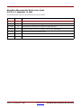
The following table shows the revision history for this document.
Version
Revision
7/22/04
1.0
Initial Xilinx release.
8/27/04
1.1
Edited content; imported new images
11/19/04
1.2
Reconfigured book; added new chapter; incorporated edits
11/30/04
1.3
Reformatted book to consist of chapters for Overview and RefDes1
1/7/05
1.3.1
7/22/05
1.4
Added Ref Des 2 chapter.
9/12/05
1.5
Made minor edits in chapters 2 and 3.
Made minor non-technical changes only.
UG133 v1.5 September 12, 2005
www.xilinx.com
MicroBlaze Microcontroller Ref Des User Guide
Preface: About This Guide
Introduction . . . . . . . . . . . . . . . . . . . . . . . . . . . . . . . . . . . . . . . . . . . . . . . . . . . . . . . . . . . . . . . . .
Guide Contents . . . . . . . . . . . . . . . . . . . . . . . . . . . . . . . . . . . . . . . . . . . . . . . . . . . . . . . . . . . . . .
Additional Resources . . . . . . . . . . . . . . . . . . . . . . . . . . . . . . . . . . . . . . . . . . . . . . . . . . . . . . . .
Conventions . . . . . . . . . . . . . . . . . . . . . . . . . . . . . . . . . . . . . . . . . . . . . . . . . . . . . . . . . . . . . . . . .
1
1
2
2
Typographical . . . . . . . . . . . . . . . . . . . . . . . . . . . . . . . . . . . . . . . . . . . . . . . . . . . . . . . . . . . . . 2
Online Document . . . . . . . . . . . . . . . . . . . . . . . . . . . . . . . . . . . . . . . . . . . . . . . . . . . . . . . . . . 3
Chapter 1: Microcontroller Reference Design Overview
Introduction . . . . . . . . . . . . . . . . . . . . . . . . . . . . . . . . . . . . . . . . . . . . . . . . . . . . . . . . . . . . . . . . . 4
Chapter 2: MicroBlaze Microcontroller
Reference Design Number 1
Reference Design Building Blocks . . . . . . . . . . . . . . . . . . . . . . . . . . . . . . . . . . . . . . . . . . . .
Application . . . . . . . . . . . . . . . . . . . . . . . . . . . . . . . . . . . . . . . . . . . . . . . . . . . . . . . . . . . . . . . . . .
Features: . . . . . . . . . . . . . . . . . . . . . . . . . . . . . . . . . . . . . . . . . . . . . . . . . . . . . . . . . . . . . . . . . . . . .
Getting Started . . . . . . . . . . . . . . . . . . . . . . . . . . . . . . . . . . . . . . . . . . . . . . . . . . . . . . . . . . . . . . .
6
6
7
7
System Requirements . . . . . . . . . . . . . . . . . . . . . . . . . . . . . . . . . . . . . . . . . . . . . . . . . . . . . . 7
Downloading the Reference Designs . . . . . . . . . . . . . . . . . . . . . . . . . . . . . . . . . . . . . . . . . 8
Downloading the Design and Launching XPS . . . . . . . . . . . . . . . . . . . . . . . . . . . . . . . . 8
Updating and Generation Hardware Files . . . . . . . . . . . . . . . . . . . . . . . . . . . . . . . . . . . . . 9
Downloading Design Files to the FPGA . . . . . . . . . . . . . . . . . . . . . . . . . . . . . . . . . . . . . . 10
Selecting a Software Application to Run When the FPGA is Configured . . . . . . . . . . 10
Loading the “Calculator_App” Software Application . . . . . . . . . . . . . . . . . . . . . . . . . . 11
Running the Calculator_App program . . . . . . . . . . . . . . . . . . . . . . . . . . . . . . . . . . . . . . . 11
Selecting a Software Application to be Loaded with a BOOT Loader after the FPGA is
Configured and the Processor is Running . . . . . . . . . . . . . . . . . . . . . . . . . . . . . . . . . 12
Updating and Generation Hardware Files . . . . . . . . . . . . . . . . . . . . . . . . . . . . . . . . . . . .
Loading the “microblaze_0_xmdstub” Software Application . . . . . . . . . . . . . . . . . . .
Loading the “TestApp” Software Application with XMD_STUB . . . . . . . . . . . . . . . .
Loading the “Calculator_App” Software Application with XMD_STUB . . . . . . . . . .
12
13
14
14
Additional MicroBlaze and EDK Information. . . . . . . . . . . . . . . . . . . . . . . . . . . . . . . . 14
Chapter 3: MicroBlaze Microcontroller
Reference Design Number 2
Reference Design Building Blocks . . . . . . . . . . . . . . . . . . . . . . . . . . . . . . . . . . . . . . . . . . .
Application . . . . . . . . . . . . . . . . . . . . . . . . . . . . . . . . . . . . . . . . . . . . . . . . . . . . . . . . . . . . . . . . .
Features: . . . . . . . . . . . . . . . . . . . . . . . . . . . . . . . . . . . . . . . . . . . . . . . . . . . . . . . . . . . . . . . . . . . .
Getting Started . . . . . . . . . . . . . . . . . . . . . . . . . . . . . . . . . . . . . . . . . . . . . . . . . . . . . . . . . . . . . .
15
15
16
17
System Requirements . . . . . . . . . . . . . . . . . . . . . . . . . . . . . . . . . . . . . . . . . . . . . . . . . . . . . 17
Downloading the Reference Designs . . . . . . . . . . . . . . . . . . . . . . . . . . . . . . . . . . . . . . . . 17
Downloading the Design and Launching XPS . . . . . . . . . . . . . . . . . . . . . . . . . . . . . . . 17
Updating and Generating Hardware Files . . . . . . . . . . . . . . . . . . . . . . . . . . . . . . . . . . . .
Downloading Design Files to the FPGA . . . . . . . . . . . . . . . . . . . . . . . . . . . . . . . . . . . . . .
Selecting a Software Application to Run When the FPGA is Configured . . . . . . . . . .
Loading the “ Project: Interrupt_demo” Software Application . . . . . . . . . . . . . . . . . .
UG133 (v1.5) September 12, 2005
www.xilinx.com
18
19
19
20
MicroBlaze Microcontroller Ref Des User Guide
Running the Interrupt_demo Program . . . . . . . . . . . . . . . . . . . . . . . . . . . . . . . . . . . . . . . 21
Selecting a Software Application to be Loaded with a BOOT Loader after the FPGA is
Configured and the Processor is Running . . . . . . . . . . . . . . . . . . . . . . . . . . . . . . . . . 21
Updating and Generating Hardware Files . . . . . . . . . . . . . . . . . . . . . . . . . . . . . . . . . . . .
Loading the microblaze_0_xmdstub Software Application . . . . . . . . . . . . . . . . . . . . .
Loading the “Interrupt_demo” Software Application with XMD_STUB . . . . . . . . . .
Loading the Simple_Clock Software Application with XMD_STUB . . . . . . . . . . . . . .
21
22
23
23
Additional MicroBlaze and EDK Information. . . . . . . . . . . . . . . . . . . . . . . . . . . . . . . . 24
UG133 (v1.5) September 12, 2005
www.xilinx.com
MicroBlaze Microcontroller Ref Des User Guide
R
Preface
About This Guide
Introduction
This user guide contains information on how to integrate the stand-alone, prebuilt,
MicroBlaze Microcontroller reference design into an FPGA. Although this design is
targeted initially for the Xilinx Spartan-3 Starter Kit Board, the design may be modified
readily for any Xilinx or third party platform.
This guide is an aid in getting started and learning how to use the Xilinx Embedded
Development Kit (EDK) tools. It does this through examples, which show how multiple
software images can be run on a defined soft Microcontroller hardware configuration.
This guide show how an FPGA with a soft processor can be used the same way an engineer
would select an off the shelf microcontroller. This guide will provide examples of a
number of different microcontroller configurations from which an engineer can choose.
The soft microcontroller features and peripherals in the FPGA may be used without
modification, or may be modified and customized using the Xilinx EDK Platform Studio
tools. This guide will cover the flow where multiple software images are load on an
unmodified hardware configuration.
The MicroBaze Microcontroller is an integrated solution intended for implementation of an
embedded controller in FPGA by a user without extensive knowledge of the Xilinx
Embedded Development Kit (EDK) and the Xilinx Platform Studio (XPS). The solution
offered in this document is a minimal implementation that can be expanded easily to
include other peripherals and application software for different usage.
All the necessary documentation, references, HDL code, sample codes, software drivers
and application software are included in the tools or provided with this design.
Guide Contents
This manual contains the following sections:
Chapter 1 “Microcontroller Reference Design Overview”
Chapter 2 “MicroBlaze Microcontroller Reference Design Number 1”
Chapter 3 “MicroBlaze Microcontroller Reference Design Number 2”
MicroBlaze Microcontroller Ref Des User Guide
UG133 (v1.5) September 12, 2005
www.xilinx.com
1
R
Additional Resources
Additional Resources
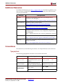
For additional information, go to http://support.xilinx.com. The following table lists some
of the resources available from this website. You can also directly access these resources
using the provided URLs.
Resource
Tutorials
Description/URL
Tutorials covering Xilinx design flows, from design entry to
verification and debugging
http://support.xilinx.com/support/techsup/tutorials/index.htm
Answer Browser
Database of Xilinx solution records
http://support.xilinx.com/xlnx/xil_ans_browser.jsp
Application Notes
Descriptions of device-specific design techniques and approaches
http://support.xilinx.com/apps/appsweb.htm
Data Sheets
Device-specific information on Xilinx device characteristics,
including readback, boundary scan, configuration, length count,
and debugging
http://support.xilinx.com/xlnx/xweb/xil_publications_index.jsp
Problem Solvers
Interactive tools that allow you to troubleshoot your design issues
http://support.xilinx.com/support/troubleshoot/psolvers.htm
Tech Tips
Latest news, design tips, and patch information for the Xilinx
design environment
http://www.support.xilinx.com/xlnx/xil_tt_home.jsp
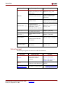
Conventions
This document uses the following conventions. An example illustrates each convention.
Typographical
The following typographical conventions are used in this document:
Convention
Meaning or Use
Example
Courier font
Messages, prompts, and
program files that the system
displays
speed grade: - 100
Courier bold
Literal commands that you
enter in a syntactical statement
ngdbuild design_name
Commands that you select
from a menu
File → Open
Keyboard shortcuts
Ctrl+C
Helvetica bold
MicroBlaze Microcontroller Ref Des User Guide
UG133 (v1.5) September 12, 2005
www.xilinx.com
2
R
Conventions
Convention
Meaning or Use
Example
Variables in a syntax
statement for which you must
supply values
ngdbuild design_name
References to other manuals
See the Development System
Reference Guide for more
information.
Emphasis in text
If a wire is drawn so that it
overlaps the pin of a symbol,
the two nets are not connected.
An optional entry or
parameter. However, in bus
specifications, such as
bus[7:0], they are required.
ngdbuild [option_name]
design_name
A list of items from which you
must choose one or more
lowpwr ={on|off}
Separates items in a list of
choices
lowpwr ={on|off}
Vertical ellipsis
.
.
.
Repetitive material that has
been omitted
IOB #1: Name = QOUT’
IOB #2: Name = CLKIN’
.
.
.
Horizontal ellipsis . . .
Repetitive material that has
been omitted
allow block
loc1 loc2 ... locn;
Italic font
Square brackets
Braces
[ ]
{ }
Vertical bar
|
block_name
Online Document
The following navigation conventions are used in this document:
Convention
Meaning or Use
Example
See the section “Additional
Resources” for details.
Blue text
Cross-reference link to a
location in the current
document
Red text
Cross-reference link to a
location in another document
See Figure 2-5 in the Virtex-II
Handbook.
Blue, underlined text
Hyperlink to a website (URL)
Go to http://www.xilinx.com
for the latest speed files.
MicroBlaze Microcontroller Ref Des User Guide
UG133 (v1.5) September 12, 2005
www.xilinx.com
Refer to “Title Formats” in
Chapter 1 for details.
3
R
Chapter 1
Microcontroller Reference Design
Overview
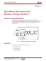
Introduction
When selecting an embedded microcontroller, typically an engineer will list the required
features and then select a stand alone, off the shelf microcontroller or processor that has
those features. In most cases there are additional features or peripherals that are not need,
but are included non-the less. When using a Soft Processor in an FPGA an engineer has an
opportunity to select from pre-created microcontroller hardware images, or modify and
customize the features and peripherals.
This guide is provided as an aid in getting started and learning how to use the Xilinx
Embedded Development Kit (EDK) tools. It does this through examples, which show how
multiple software images can run on a defined soft microcontroller hardware
configuration. This guide show how an FPGA with a soft processor can be used the same
way an engineer would select an off the shelf microcontroller. This guide will provide
examples of a number of different microcontroller configurations from which an engineer
can choose. The soft microcontroller features and peripherals in the FPGA may be used
without modification, or may be modified and customized using the Xilinx EDK Platform
Studio tools. This guide will cover the flow where multiple software images are loaded on
an unmodified hardware configuration.
MicroBlaze Microcontroller Ref Des User Guide
UG133 (v1.5) September 12, 2005
www.xilinx.com
4
Chapter 1: Microcontroller Reference Design Overview
5
www.xilinx.com
R
MicroBlaze Microcontroller Ref Des User Guide
UG133 (v1.5) September 12, 2005
R
Reference Design Building Blocks
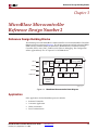
Chapter 2
MicroBlaze Microcontroller
Reference Design Number 1
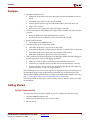
Reference Design Building Blocks
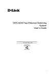
The block diagram of the MicroBlaze Microcontroller used in this MicroBlaze
Microcontroller Reference Design is shown in Figure 2-1. The design includes an Internal
Block RAM memory, an RS232 UART, 4 GPIO blocks, and a JTAG_UART used for
software debugging. This configuration utilizes approximately 50% of a Spartan-3™
XC3S200 device.
Figure Top x-ref 2-1
Clock
MicroBlaze DOPB
CPU
Core
OPB
Reset
ILMB
DLMB
Interrupt
UART
4X
GPIO
JTAG_UART
JTAG Ports
A
B
Dual Ported
BlockRAM
(BRAM)
xip312
Figure 2-1:
MicroBlaze Microcontroller Block Diagram
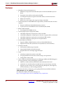
Application
Some applications for the MicroBlaze processor include:
•
Industrial Controller
•
Consumer Application
•
Office Automation
•
Data Communication
MicroBlaze Microcontroller Ref Des User Guide
UG133 (v1.5) September 12, 2005
www.xilinx.com
6
R
Features:
Features:
•
•
•
MicroBlaze Microprocessor
♦
50 MHz on the Spartan-3 Starter Kit Board, derived from the 50 MHz crystal on
board
♦
Instruction cache and data cache options disabled
♦
32 32-bit general purpose registers with 32-bit address and 32-bit data buses
♦
Single cycle execution
♦
Direct access to the register file using Fast Simplex Link (FSL)
Unified instruction and data BRAM into single memory for both instruction and data
segments
♦
Dual port 16 KB internal blockRAM memory structure
♦
2-cycle read access from BRAM via the Local Memory Bus (LMB)
RS232 UART Controller
♦
•
•
Pre-configured for 57600 baud rate
General purpose input/output ports (GPIO)
♦
8-bit GPIO configured as output ports to drive LED
♦
12-bit GPIO configured as output ports to drive the 7-segment LEDs on the board
♦
8-bit GPIO configured as input ports to read onboard dip switches
♦
3-bit GPIO configured as input ports to read push buttons
JTAG_UART core with Xilinx Microprocessor Debugger (XMD) and GDB debugger to
provide application/software debugging capabilities
♦
XMD uses a JTAG_UART to communicate with xmdstub on the board
♦
xmdstub is an executable software loaded into local system memory at startup
♦
Supports run time control, such as Run, Single Step, Breakpoint, View Registers,
and View Memory, as well as debug parameters
Note: Interrupts are not used in this design. For an example on how to use interrupts, see
the Microblaze design using an OPB interrupt controller and an OPB microprocessor
debug module (MDM) reference design available on the Embedded Design Kit web site at
http://www.support.xilinx.com/ise/embedded/edk_examples.htm
For documentation on interrupts, see the MicroBlaze Processor Reference Guide in the EDK
documentation.
Getting Started
System Requirements
The following software must be installed on your PC to utilize this reference design:
•
Windows 2000 SP2/Windows XP
•
EDK 6.3 or later (Must be the same version as ISE)
•
ISE 6.3i or later
MicroBlaze Microcontroller Ref Des User Guide
UG133 (v1.5) September 12, 2005
www.xilinx.com
7
R
Downloading the Design and Launching XPS
To download the completed reference design, the following hardware is required:
•
Xilinx Spartan-3 Evaluation Board. For information on the evaluation board, see
http://www.xilinx.com/products/spartan3/s3boards.htm.
•
Xilinx Parallel Cable used to program and debug the device
•
Serial Cable for connection to the RS232 UART via HyperTerminal
The next sections of this document will discuss:
•
Downloading the reference design and test application
•
Launching Xilinx Platform Studios (XPS)
Downloading the Reference Designs
Go to the MicroBlaze lounge at http://www.xilinx.com/microblaze_mcu_refdes1.
Download the reference design, starting with the MB_MCU_RefDes1.zip archive.
Downloading the Design and Launching XPS
1.
Go to the MicroBlaze lounge at http://www.xilinx.com/microblaze_mcu_refdes1 and
download the MB_MCU_RefDes1.zip archive.
2.
On the target drive, unzip the mb_mcu_Refdes2-EDK7-1.zip file. This will
automatically create a subdirectory for the project MB_MCU_RefDes1.zip. Assuming
that the Xilinx Platform Studio (XPS) has been installed, launch XPS at this time using
Start>Programs>Xilinx Platform Studio>Xilinx Platform Studio.
3.
Once in XPS, select the menu option File>Open Project.
4.
Using the browser, navigate to where the project exists and double-click on
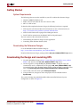
System.xmp.
The system showing the prebuilt MicroBlaze Microcontroller Reference System
configuration is shown in Figure 2-1.
MicroBlaze Microcontroller Ref Des User Guide
UG133 (v1.5) September 12, 2005
www.xilinx.com
8
R
Downloading the Design and Launching XPS
Figure Top x-ref 2-2
Figure 2-2:
Xilinx Platform Studio (XPS)
Updating and Generation Hardware Files
At this point XPS is open with the selected hardware application. No modifications are
needed to run this design. All the hardware features and peripherals have been pre-loaded
and pre-set. The Hardware Application can run any number of software applications.
When the Base System Wizard is used to create a Hardware System, it also will create a
simple Software Application to test the selected Hardware features and peripherals
To be sure that all the Hardware files have been created, in XPS, please select
Tools>Update Bitstream. This will run any of the programs needed to generate the
Hardware Application for this reference design.
The message panel should read:
...
Memory Initialization completed successfully.
Done.
or, if all files are up to date, then it will read:
...
make: Nothing to be done for `init_bram'.
Done.
MicroBlaze Microcontroller Ref Des User Guide
UG133 (v1.5) September 12, 2005
www.xilinx.com
9
R
Downloading the Design and Launching XPS
Downloading Design Files to the FPGA
The following two sections illustrate two methods of downloading a software application
into the FPGA. The first method is when the software application can be incorporated into
the FPGA bitstream. The second method illustrates loading a selected application into the
FPGA using the GDB debugger for software development and debugging.
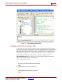
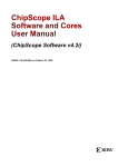
Selecting a Software Application to Run When the FPGA is Configured
In this step the software application that will be loaded when the FPGA is initially loaded
with a new bitstream will be selected. Select the XPS Software Application tab. There are
3 options that can be selected when choosing the Software Application. This first example
will show how a Software Application can be initially added to the FPGA bitstream. This
will configure the MicroBlaze Microcontroller program and Data memory with the
software application already pre-loaded. This means that as soon as the FPGA has been
successfully configured, the MicroBlaze Microcontroller software application will already
be running on the MicroBlaze Microcontroller Hardware Application.
In this case, although multiple software applications could overlap in the Bram, only one
software application can be selected at one time. To select the desired application, perform
the following steps:
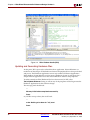
1.
Select the Application tab the XPS window.
2.
Right click on Project: Calculator_App.
3.
Set Mark to Initialize BRAMs. A small green arrow appear to the left of the Project:
Calculator_App text.
4.
Confirm that Mark to Initialize BRAMs is not checked for the other projects and
default applications. The Graphic to the left of each other application should appear as
a green arrow with a red ‘X’ over it. Verify that this is the case for
microblaze_0_bootloop, microblaze_0_xmdstub, and Project: TestApp. If any are
set, please Right click and confirm that Mark to Initialize BRAMs is not checked. If
checked, click to deselect it. The green arrow should then appear with a red “X”.
Figure 2-3:
Software Selection when FPGA is Configured
MicroBlaze Microcontroller Ref Des User Guide
UG133 (v1.5) September 12, 2005
www.xilinx.com
10
R
Downloading the Design and Launching XPS
Loading the “Calculator_App” Software Application
To configure the hardware system and to load the software application into the Spartan-3
Evaluation Board using the Digilent JTAG3 cable, perform the following steps:
1.
Connect the Digilent JTAG3 cable to the J7 header on the Spartan-3 Evaluation Board
and connect the other end to the parallel port of the PC. If using the Parallel Cable IV,
make sure that the status light is lit on the cable.
2.
Connect the Serial cable to J2 on the Spartan-3 Evaluation Board and to the serial port
of the PC. On the PC, using hyperterminal, make certain that the bit rate is set for
57600 bps and No Parity of the the serial port.
3.
Turn on the power on to the Spartan-3 Evaluation Board.
4.
In XPS, to make sure that the ELF file is up to date, use Tools>Update Bitstream.
There may be a warning, Processor microblaze_0 has XMDSTUB-mode
application, but xmdstub.elf is not marked for download, do you want to
continue? Click YES.
5.
In XPS, select Tools>Download to download the new bitstream into the FPGA. The
xmd-stub warning will appear again. Please click YES.
Note: Close all other XMD and GDB windows prior to downloading a configuration bits.
Running the Calculator_App program
After the Calculator_App has been loaded, the hyperterminal should show:
Simple Calculator App for Spartan-3 Starter Kit
Push button to start math operation...
The Calculator_App is a simple 3 function calculator. The 3 right most push button
switches are Add (BTN0), Sub (BTN1), Mult (BTN2). The left most push button switch
(BTN3) is a program reset, which will clear the calculator program. If the reset is pushed at
this time, then the FPGA will need to be re-loaded.
The eight toggle switches directly under the 7-Segment display are divided into two 4 bit
words. When the Add, Sub, or Mult push button switches are pushed, the selected
calculator operation will be performed on the value of the toggle switches. If the toggle
switches are set to:
Sw7=off, Sw6=off, Sw5=off, Sw4=off, Sw3=off, Sw2=off, Sw1=off, Sw0=off
Where Word 1 is 0 and Word 0 is 0
Add: 0+0=0
Sub: 0-0=0
Mult 0*0=0
If the toggle switches are set to:
Sw7=off, Sw6=off, Sw5=off, Sw4=ON, Sw3=off, Sw2=off, Sw1=ON, Sw0=ON
Where Word 1 is 1 and Word 0 is 3
Add: 3+1=4
Sub: 3-1=2
Mult 3*1=3
MicroBlaze Microcontroller Ref Des User Guide
UG133 (v1.5) September 12, 2005
www.xilinx.com
11
R
Selecting a Software Application to be Loaded with a BOOT Loader after the FPGA is
Each time one of the Push Button switches is pressed, the result should be displayed in
decimal on the 7-Seg display, and it will also be sent to the hyperterminal through the
UART. The hyperterminal display should show:
3+1=4
Push button to start math operation...
3-1=2
Push button to start math operation...
3*1=3
Push button to start math operation...
The next section will show how to load this same program after the FPGA has been
configured.
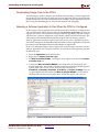
Selecting a Software Application to be Loaded with a BOOT
Loader after the FPGA is Configured and the Processor is Running
This step will show an example of how a Hardware Application can be initially loaded
with a Stub program. This will configure the MicroBlaze Microcontroller where it is
waiting to be loaded with the actual software application.
Updating and Generation Hardware Files
Select the XPS Software Application tab. There are 3 options that can be selected when
choosing selecting this tab. This example will show how a software application can be
loaded after the FPGA is configured. A software application can be loaded and run, and
then a different software application can be loaded and run. In this example the
MicroBlaze processor must be loaded with a software application through the use of a
stub program.
To select the stub application, perform the following steps:
1.
Select the Application tab the XPS window.
2.
Right click on Default: microblaze_0_xmdstub.
3.
Set Mark to Initialize BRAMs. A small green arrow will appear to the left of the
Default: microblaze_0_xmdstub text.
4.
Confirm that Mark to Initialize BRAMs is not checked for the other projects and
default applications. The graphic to the left of each other application should appear as
a green arrow with a red ‘X’ over it. Verify that this is the case for
microblaze_0_bootloop, Project: TestApp, and Project: Calculator_App. If any are
set, right click and confirm that Mark to Initialize BRAMs is not checked. If checked,
click to deselect it. The green arrow should then appear with a red “X”.
MicroBlaze Microcontroller Ref Des User Guide
UG133 (v1.5) September 12, 2005
www.xilinx.com
12
R
Selecting a Software Application to be Loaded with a BOOT Loader after the FPGA is
Figure 2-4:
Software Selection with a BOOT loader
Loading the “microblaze_0_xmdstub” Software Application
To configure the hardware system and to load the software application into the Spartan-3
Evaluation Board using the Digilent JTAG3 cable, perform the following steps:
1.
Connect the Digilent JTAG3 cable to the J7 header on the Spartan-3 Evaluation Board
and connect the other end to the parallel port of the PC. If using the Parallel Cable IV,
make sure that the status light is lit on the cable.
2.
Connect the Serial cable to J2 on the Spartan-3 Evaluation Board and to the serial port
of the PC. On the PC, using hyperterminal, make certain that the bit rate is set for
57600 bps on the serial port.
3.
Turn on the power to the Spartan-3 Evaluation Board.
4.
In XPS, to make sure that the ELF file is up to date, select Tools>Update Bitstream.
Note: Close all other XMD and GDB windows before downloading the configuration bits.
5.
In XPS, select Tools>Download to download the hardware configuration and load
xmdstub into the BRAM memory.
Note: Close all other XMD and GDB windows before downloading the configuration bits.
6.
In XPS, select Tools>XMD to open an XMD utility.
XMD is a JTAG utility that can be used to download and debug software. XMD is also a
server for GDB, the GNU debugging utility.
MicroBlaze Microcontroller Ref Des User Guide
UG133 (v1.5) September 12, 2005
www.xilinx.com
13
R
Additional MicroBlaze and EDK Information
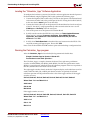
Loading the “TestApp” Software Application with XMD_STUB
1.
In XPS, select Tools>Software Debugger to open the GDB interface (Source
Window).
2.
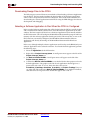
Choose TestApp from the User Application window.
3.
In GDB, select File>Target Settings to display the Target Selection dialog box as
shown in Figure 2-5.
4.
Configure the Target Selection dialog box to match Figure 2-5, then click OK.
5.
In Source Window>Run, click RUN to download the executable .elf file located in the
TestApp directory into the device.
6.
In Source Window, the user can select Continue, Single Step, Set Break Point, and
view source code, registers, and memory contents.
7.
From Control Tag, select Continue.
If the Spartan-3 Evaluation Board executes the application test program properly, you
will see flashing LEDs on the board in the Hyper Terminal (57600bps, 8N1).
Note: Begin from step 2 to configure the device prior to loading a new application program and
debugging. Make certain to close all XMD and GDB windows.
Figure Top x-ref 2-3
Figure 2-5:
Target Selection for Software Debugger
Loading the “Calculator_App” Software Application with XMD_STUB
To download and execute the Calculator_App demonstration program, repeat the
procedure in section Loading the “TestApp” Software Application with XMD_STUB.
Start with step 1 and choose Calculator_App in step 5 instead of TestApp. See Running
the Calculator_App program
Additional MicroBlaze and EDK Information
Congratulations, you have successfully integrated a MicroBlaze Microcontroller into an
FPGA and executed software code.
For additional information on MicroBlaze and the EDK tools, go to
http://support.xilinx.com.
MicroBlaze Microcontroller Ref Des User Guide
UG133 (v1.5) September 12, 2005
www.xilinx.com
14
R
Reference Design Building Blocks
Chapter 3
MicroBlaze Microcontroller
Reference Design Number 2
Reference Design Building Blocks
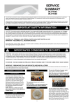
The block diagram of the MicroBlaze™ Microcontroller used in this MicroBlaze Controller
Reference Design is shown in Figure 3-1. The design components include an Internal Block
RAM memory, an RS232 UART, 4 GPIO blocks, SRAM Memory Controller, Interrupt
Controller, Timer, and a JTAG_UART used for software debugging. This configuration
utilizes approximately 79% of a Spartan™-3 XC3S200 device.
Clock
MicroBlaze
DOPB
CPU
Core
Reset
ILMB
Interrupt
Interrupt
Controller
Timer
External Memory
Controller (EMC)
OPB
Bus
DLMB
UART
JTAG Ports
A
4X
GPIO
JTAG_UART
B
Dual Ported
BlockRAM
(BRAM)
ug133_02_01
Figure 3-1:
MicroBlaze Microcontroller Block Diagram
Application
Some applications for the MicroBlaze processor include:
•
Industrial Controller
•
Consumer Application
•
Office Automation
•
Data Communication
MicroBlaze Microcontroller Ref Des User Guide
UG133 (v1.5) September 12, 2005
www.xilinx.com
15
Chapter 3: MicroBlaze Microcontroller Reference Design Number 2
R
Features:
•
•
•
MicroBlaze Version 4 Microprocessor
♦
50 MHz on the Spartan-3 Starter Kit Board, derived from the 50 MHz crystal on
board
♦
Instruction cache and data cache options disabled
♦
32, 32-bit general purpose registers with 32-bit address and 32-bit data buses
♦
Single cycle execution
♦
Direct access to the register file using Fast Simplex Link (FSL)
Unified instruction and data BRAM into single memory for both instruction and data
segments
♦
Dual port 16 KB internal blockRAM memory structure
♦
2-cycle read access from BRAM via the Local Memory Bus (LMB)
RS232 UART Controller
♦
•
•
•
•
•
Pre-configured for 57600 baud rate
General purpose input/output ports (GPIO)
♦
8-bit GPIO configured as output ports to drive the LEDs
♦
12-bit GPIO configured as output ports to drive the 7-segment LEDs on the board
♦
8-bit GPIO configured as input ports to read onboard DIP switches
♦
3-bit GPIO configured as input ports to read push buttons
External Memory Controller
♦
Supports 1MByte of SRAM memory with two, 256x16 SRAM Devices
♦
Supports flash and other synchronous and asynchronous external memory
Interrupt Controller
♦
Parameterizes OPB Interrupt Controller
♦
Programmable Enable or Disable Interrupts
♦
Programmable Level and Edge trigger Interrupts
Timer
♦
32-bit Timer module that attaches to the OPB
♦
Two programmable interval timers with interrupt, event generation.
♦
Configurable counter width
JTAG_UART core with Xilinx Microprocessor Debugger (XMD) and GDB debugger to
provide application/software debugging capabilities
♦
XMD uses a JTAG_UART to communicate with xmdstub on the board
♦
xmdstub is an executable software loaded into local system memory at startup
♦
Supports run time control, such as Run, Single Step, Breakpoint, View Registers,
and View Memory, as well as debug parameters
For the latest data sheet, see the proc_ip_ref_guide.pdf file located at EDK installation:
<EDK>\doc\proc_ip_ref_guide.pdf
For additional examples and reference designs, see:
http://www.support.xilinx.com/ise/embedded/edk_examples.htm
16
www.xilinx.com
MicroBlaze Microcontroller Ref Des User Guide
UG133 (v1.5) September 12, 2005
R
Getting Started
Getting Started
System Requirements
The following software must be installed on your PC to utilize this reference design:
•
Windows 2000 SP2/Windows XP
•
EDK 7.1 SP1 or later (Must be the same version as ISE)
•
ISE™ 7.1i SP2 or later
To download the completed reference design, the following hardware is required:
•
Xilinx Spartan-3 Evaluation Board. For information on the evaluation board, see
http://www.xilinx.com/products/spartan3/s3boards.htm.
•
Xilinx Parallel Cable used to program and debug the device
•
Serial Cable for connection to the RS232 UART via HyperTerminal
The next sections of this document will discuss:
•
Downloading the reference design and test application
•
Launching Xilinx Platform Studios (XPS)
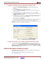
Downloading the Reference Designs
Go to the MicroBlaze Microcontroller lounge at
http://www.xilinx.com/microblaze_mcu_refdes2-EDK7-1.
Download the reference design, starting with the mb_mcu_Refdes2-EDK7-1.zip archive.
Downloading the Design and Launching XPS
1.
Go to the MicroBlaze lounge at http://www.xilinx.com/microblaze_mcu_refdes2EDK7-1 and download the mb_mcu_Refdes2-EDK7-1.zip archive.
2.
On the target drive, unzip the mb_mcu_Refdes2-EDK7-1.zip file. This will
automatically create a subdirectory for the project mb_mcu_Refdes2-EDK7-1.zip.
Assuming that the Xilinx Platform Studio (XPS) has been installed, launch XPS at this
time using Start>Programs>Xilinx Platform Studio>Xilinx Platform Studio.
3.
Once in XPS, select the menu option File>Open Project.
4.
Using the browser, navigate to where the project exists and double click on
System.xmp.
The system showing the prebuilt MicroBlaze Microcontroller Reference System
configuration is shown in Figure 3-2.
MicroBlaze Microcontroller Ref Des User Guide
UG133 (v1.5) September 12, 2005
www.xilinx.com
17
Chapter 3: MicroBlaze Microcontroller Reference Design Number 2
R
Figure Top x-ref 3-1
Figure 3-2:
Xilinx Platform Studio (XPS)
Updating and Generating Hardware Files
At this point, XPS is open to the selected hardware application. No modifications are
needed to run this design. All the hardware features and peripherals have been pre-loaded
and pre-set. The Hardware Application can run any number of Software Applications.
When the Base System Wizard is used to create a Hardware System, it will create also a
simple Software Application to test the selected Hardware features and peripherals
To make certain that all the Hardware files have been created, in XPS, select
Tools>Update Bitstream. Doing so will run any of the programs needed to generate the
Hardware Application for this reference design.
The message panel should read:
...
Memory Initialization completed successfully.
Done.
or, if all files are up to date, then it will read:
...
make: Nothing to be done for `init_bram'.
Done.
18
www.xilinx.com
MicroBlaze Microcontroller Ref Des User Guide
UG133 (v1.5) September 12, 2005
R
Downloading the Design and Launching XPS
Downloading Design Files to the FPGA
The following two sections illustrate two methods of downloading a Software Application
into the FPGA. The first method outlines the downloading of the Software Application
when it can be incorporated into the FPGA bitstream. The second method describes the
downloading of a selected application into the FPGA using the GDB debugger for software
development and debugging.
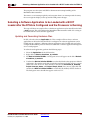
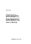
Selecting a Software Application to Run When the FPGA is Configured
In this step the Software Application that will be loaded when the FPGA is initially loaded
with a new bitstream will be selected. Please select the Software Application tab on XPS
window. The first example will show how a Software Application can be initially added to
the FPGA bitstream. This will configure the MicroBlaze Microcontroller program and Data
memory with the software application already pre-loaded. This means that as soon as the
FPGA has been successfully configured, the MicroBlaze Microcontroller Software
Application will already be running on the MicroBlaze Microcontroller Hardware
Application.
In this case, although multiple software applications could overlap in the BRAM, only one
software application can be selected at one time. To select the desired application, perform
the following steps:
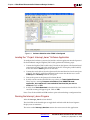
1.
Select the Application tab the XPS window.
2.
Right click on Project: Interrupt_demo. A small green arrow appear to the left of the
Project: Interrupt_demo text.
3.
Set Mark to Initialize BRAMs. A small green arrow will appear to the left of the
Project: Interrupt_demo text.
4.
Confirm that Mark to Initialize BRAMs is not checked for the other projects or for the
default applications. The graphic to the left of each application should appear as a
green arrow with a red ‘X’ over it. Verify that this is the case for
microblaze_0_bootloop, microblaze_0_xmdstub, and Project: TestApp. If any are
set, right click and confirm that Mark to Initialize BRAMs is not checked. If checked,
click to deselect it. The green arrow should then appear with a red “X”.
MicroBlaze Microcontroller Ref Des User Guide
UG133 (v1.5) September 12, 2005
www.xilinx.com
19
Chapter 3: MicroBlaze Microcontroller Reference Design Number 2
Figure 3-3:
R
Software Selection when FPGA is Configured
Loading the “ Project: Interrupt_demo” Software Application
To configure the hardware system and to load the software application into the Spartan-3
Evaluation Board using the Digilent JTAG3 cable, perform the following steps:
1.
Connect the Digilent JTAG3 cable to the J7 header on the Spartan-3 Evaluation Board
and connect the other end to the parallel port of the PC. If using the parallel cable IV,
make sure that the status light is lit on the cable.
2.
Connect the serial cable to J2 on the Spartan-3 Evaluation Board and to the serial port
of the PC. On the PC, using HyperTerminal, make certain that the bit rate is set for
57600 bps and No Parity of the the serial port.
3.
Turn on the power to the Spartan-3 Evaluation Board.
4.
In XPS, to make sure that the ELF file is up to date, use Tools>Update Bitstream.
There may be a warning Processor microblaze_0 has XMDSTUB-mode
application, but xmdstub.elf is not marked for download, do you want to
continue? Click on YES.
5.
In XPS, select Tools>Download to download the new bitstream into the FPGA. The
xmd-stub warning will appear again. Click on YES.
Note: Close all other XMD and GDB windows prior to downloading a configuration bits.
Running the Interrupt_demo Program
After the Interrupt_demo has been loaded:
The 8-bit LEDs on the board begins to toggle back and forth while the Seven Segment
Display starts to increment.
The main.c under Interrupt_demo/src contains the main source for this application.
20
www.xilinx.com
MicroBlaze Microcontroller Ref Des User Guide
UG133 (v1.5) September 12, 2005
R
Selecting a Software Application to be Loaded with a BOOT Loader after the FPGA is
This program uses the timer and GPIO to demonstrate interrupt handling of the
MicroBlaze Microcontroller.
The timer is set to interrupt regularly and everytime there is an interrupt with the timer,
the seven segment display counts up and the LED pattern changes.
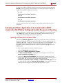
Selecting a Software Application to be Loaded with a BOOT
Loader after the FPGA is Configured and the Processor is Running
This step will show an example of how a hardware application can be initially loaded with
a stub program. This will configure the MicroBlaze Microcontroller while it is waiting to
be loaded with the actual software application.
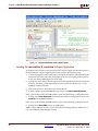
Updating and Generating Hardware Files
In XPS, select the software Application tab. This example will show how a software
application can be loaded after the FPGA is configured. A software applications can be
loaded and run, and then a different software application can be loaded and run. In this
example the MicroBlaze processor must be loaded with a software application through the
use of a stub program.
To select the stub application, perform the following steps:
1.
Select the Application tab the XPS window.
2.
Right click on Default: microblaze_0_xmdstub.
3.
Set Mark to Initialize BRAMs. A small green arrwo will appear to the left of Default:
microblaze_0_xmdstub.
4.
Confirm that Mark to Initialize BRAMs is not checked for the other projects or default
applications. The graphic to the left of each other application should appear as a green
arrow with a red ‘X’ over it. Verify that this is the case for microblaze_0_bootloop,
Project: Interrupt_demo, and Project: Simple_Clock. If any are set, right click and
confirm that Mark to Initialize BRAMs is not checked. If checked, click to deselect it.
The little green arrow should then appear with a red “X”.
MicroBlaze Microcontroller Ref Des User Guide
UG133 (v1.5) September 12, 2005
www.xilinx.com
21
Chapter 3: MicroBlaze Microcontroller Reference Design Number 2
Figure 3-4:
R
Software Selection with a BOOT loader
Loading the microblaze_0_xmdstub Software Application
To configure the hardware system and to load the software application into the Spartan-3
Evaluation Board using the Digilent JTAG3 cable, perform the following steps:
1.
Connect the Digilent JTAG3 cable to the J7 header on the Spartan-3 Evaluation Board
and connect the other end to the parallel port of the PC. If using the parallel cable IV,
make sure that the status light is lit on the cable.
2.
Connect the serial cable to J2 on the Spartan-3 Evaluation Board and to the serial port
of the PC. On the PC, using HyperTerminal, make certain that the bit rate is set for
57600 bps on the serial port.
3.
Turn on the power to the Spartan-3 Evaluation Board.
4.
In XPS, to make sure that the ELF file is up to date, use Tools>Update Bitstream.
Note: Close all other XMD and GDB windows prior to downloading a configuration bits.
5.
In XPS, select Tools>Download to download the hardware configuration and to load
xmdstub into the BRAM memory.
Note: Close all other XMD and GDB windows prior to downloading a configuration bits.
6.
In XPS, select Tools>XMD to open an XMD utility.
XMD is a JTAG utility that can be used to download and debug software. XMD is also a
server for GDB, the GNU debugging utility.
22
www.xilinx.com
MicroBlaze Microcontroller Ref Des User Guide
UG133 (v1.5) September 12, 2005
R
Selecting a Software Application to be Loaded with a BOOT Loader after the FPGA is
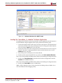
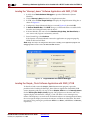
Loading the “Interrupt_demo” Software Application with XMD_STUB
1.
In XPS, select Tools>Software Debugger to open the GDB interface (Source
Window).
2.
Choose Interrupt_demo from the User Application window.
3.
In GDB, select the File>Target Settings to display the Target Selection dialog box as
shown in Figure 3-5.
4.
Configure the Target Selection dialog box to match Figure 3-5, then click OK.
5.
In Source Window>Run, click RUN. Doing so, will download the executable.elf file
located in the TestApp directory into the device.
6.
In Source Window, the user can select Continue, Single Step, Set Break Point, to
view source code, registers and memory contents.
7.
From Control Tag, select Continue.
If the Spartan-3 Evaluation Board executes the application test program properly,
LEDS on the board will flash.
Note: Begin from step 2 to configure the device prior to loading a new application program and
debugging. Make certain to Close all XMD and GDB windows.
Figure Top x-ref 3-2
Figure 3-5: Target Selection for Software Debugger
Loading the Simple_Clock Software Application with XMD_STUB
To download and execute the Simple_Clock demonstration program, repeat the
procedure in the Loading the Interrupt_demo Software Application with XMD_STUB
section, beginning with step 1. In step 5, choose Simple_Clock instead of Interrupt_demo.
See the Running the Simple_Clock program. This program uses the timer and seven
segment display to demonstrate a Simple_ Clock. The timer is set to interrupt every
minute. The frequency is set in the code. Each time that there is an interrupt from the timer,
the seven segment display increments the minutes and Hours and the LEDs. The initial
time can be set by pressing the push button BTN2 to set Hours, and BTN1 to set Minutes,
respectively.
MicroBlaze Microcontroller Ref Des User Guide
UG133 (v1.5) September 12, 2005
www.xilinx.com
23
Chapter 3: MicroBlaze Microcontroller Reference Design Number 2
R
Additional MicroBlaze and EDK Information
Congratulations, you have successfully integrated a MicroBlaze Microcontroller into an
FPGA and executed software code.
For additional information on the MicroBlaze Microcontroller and the EDK tools, see
http://support.xilinx.com.
24
www.xilinx.com
MicroBlaze Microcontroller Ref Des User Guide
UG133 (v1.5) September 12, 2005