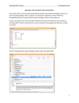
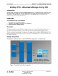
1
University of Toronto
ECE532 Digital Hardware
Module m02: Adding IP and Device Drivers — GPIO and Polling
Version for EDK 10.1.03 as of January 7, 2009
Acknowledgement
This lab is derived from a Xilinx lab given at the University of Toronto EDK workshop in November 2003.
Many thanks to Xilinx for allowing us to use and modify their material.
Goals
• Use Xilinx tools to add to the basic MicroBlaze system that was built in Module m01. A primary goal
of this lab is to understand more details about adding IP into the system without the Base System
Builder and using device drivers.
• Use the General Purpose I/O (GPIO) IP core together with the associated device driver. The GPIO
will be added to the project and used to turn on and off User LED 0 on the board. You will manipulate
the state of the LED from XMD and by using a program.
• Get an introduction to the use and structure of driver code.
Prerequisites
Module m01: Building a MicroBlaze System in XPS
Preparation
• The GPIO is a simple parallel I/O port that has similar functions to the PIT used on the GIZMO
board. You can have from 1 to 32 input/output ports, which corresponds to the processor having a 32bit bus. If you use fewer than 32 ports, the advantage of working in the FPGA synthesis environment
is that you will only instantiate logic for the number of ports that you require.
If you are on an installed system, find the overview of the XPS GPIO in the Processor IP Reference
Guide. The Guide is provided: Go to Help → EDK Online Documentation in XPS. In the Guide you
will find a link to the datasheet. Familiarize yourself with how this block works.
• Also, the Device Driver Programmer Guide is only available via the documentation tree of an installed
system. Xilinx provides device drivers so that the user may create applications quickly and easily.
The Device Driver Programmer Guide documents many details of the device drivers and software
infrastructure. You should get familiar with this section as you may eventually need to write your own
drivers. In this lab you will be required to modify some code to properly use the existing drivers.
• You will start modifying code in this lab. If you are not familiar with any source code control system,
you can quickly learn one by doing man rcsintro on any Unix system. Using such a system is
highly recommended and just plain good software engineering practice. You will need to run the
commands from a window connected to one of the UGSPARCs. There is an SSH terminal program in
the Courseware folder.
• You will need another 15MB of disk space. You can clean the files created in Module m01 via the
Hardware and Software menus to save some space.
1
University of Toronto
ECE532 Digital Hardware
Module m02: Adding IP and Device Drivers — GPIO and Polling
Background
Processor IP is an integral part of a System-On-Chip (SOC) system. Xilinx provides a variety of processor
IP cores that can quickly and easily be integrated into a system using XPS.
This module builds from Module m01 and assumes that the user has completed Module m01. A basic
understanding of the EDK tools should have been gained from Module m01.
Setup
1. Copy the XPS project directory (lab1 folder) of the previous lab and rename the copy to lab2. This will
be the working project directory for this lab. Extract m02.zip from the into the directory containing
lab2 to add the source files required for this module to the lab2/code/ directory. If you like, you can
delete the existing lab2/code/ directory before extracting m02.zip to clean up the files from Module
m01.
2. Start XPS by going to Start → Programs → Xilinx ISE Design Suite 10.1 → EDK → Xilinx Platform
Studio.
3. From the initial startup screen, select Open a Recent Project and click OK. Browse to the system.xmp
file of in the lab2 directory. Click Open to open the project. This is the project you completed in
Module m01.
Adding A GPIO With User LED 0
4. Examine all the options in the System Assembly View to look at the various aspects of the system that
you have already built. Think about how hard it would have been to do this from scratch! Having
validated (tested) ready-to-use function blocks can significantly improve your design cycle.
5. From the IP Catalog tab on the left, expand the General Purpose IO tab. Double click XPS General
Purpose IO 1.00.a to add it to the project.
6. In the System Assembly View, select Addresses from the Filters panel. Set the base address of the
xps gpio 0 to 0x80040000. The base address is the first address that will be decoded by the peripheral
on the On-chip Peripheral Bus (XPS here).
Set the Size to be 512. This will automatically set the High Address of the device to 0x800401ff,
which uses the minimum amount of memory space as displayed for the device.
What do you expect the tool to be doing with this information?
7. Select Bus Interface tab in System Assembly View from the Filters panel. The lines on the left show the
peripheral bus interfaces in the design and how the peripherals interfaces are attached to the buses. To
understand what the boxes and circles are, place cursor over desired item. A filled shape means that
the interface is connected, and a shape outline means that the interface is unconnected. Clicking a
shape allows the interface to toggle its status between connected and unconnected. Click on the open
circle next to the xps gpio 0 instance to make it a slave on the mb plb PLB instance.
8. Right click on the xps gpio instance and select Configure IP.... Clicking the Datasheet button opens
the specification for the IP. Review the parameters that can be set and the signals that constitute the
hardware interface for this IP.
Parameters are implemented in the IP using VHDL generics. This feature of VHDL is a large advantage
for IP that must fit many different applications.
2
University of Toronto
ECE532 Digital Hardware
Module m02: Adding IP and Device Drivers — GPIO and Polling
9. Select the GPIO Data Channel Width parameter and change its value from 32 to 1 such that there is
only 1 bit of general purpose I/O. The general purpose I/O will be an output to control an LED on
the board. Click OK.
10. Select Ports. Depending on the filters you have set, this view can be very lengthy. Hint: Right
click the row containing the column headers and ensure Flat View is not selected. Scroll to find the
xps gpio instance, expand its subtree, and select the GPIO IO signal. In the Net dropdown box,
select Make External. This adds the GPIO IO signal to the list of External Ports, assigning the name
xps gpio 0 GPIO IO to the external port by default.
What do you expect the tool to do with this information?
Notice that the GPIO signal is external such that it will be pinned out of the design and connected to
a pin of the FPGA. In order to control User LED 0 via the GPIO, the designer must ensure that the
LED is connected to the same FPGA pin as the synthesized GPIO hardware.
Building The System With GPIO
11. Select the Project menu and the Project Options... submenu. Select the HDL and Simulation tab and
ensure that Verilog is selected as the HDL type in the HDL panel.
12. Select the Hardware menu and the Generate Netlist submenu. This will take a few minutes to complete.
This step is updating the system and resynthesizing it, this time with the GPIO IP included. When
the synthesis completes, the design is not yet ready to be programmed into the FPGA — recall that
the netlist must be mapped, placed, routed, and converted into a bitstream first.
Generating the netlist can be considered the “logical implementation” step of the synthesis flow,
whereas the mapping, placement, and routing can be considered the “physical implementation” steps.
In this step, we perform only the logical implementation step so that we can constrain our design prior
to the physical implementation step — recall that the GPIO IP must be connected to the same physical
pin on the FPGA as User LED 0.
13. In the Project tab on the left, expand the Project Files tree and double click on UCF File: data/system.ucf.
This opens the file in an editor window. This file contains the design inputs and outputs to specific
pins of the FPGA. Edit the UCF file to connect bit 0 of the GPIO IO signal to User LED 0 by adding
the line:
Net xps gpio 0 GPIO IO<0> LOC=***;
Net xps gpio 0 GPIO IO<0> IOSTANDARD=LVTTL;
where *** is AC4 for XUPV2P board. Save this file once you’ve made your changes.
Hint: if you’re using the XUPV2P board, consult to the User Constraint File (UCF) in the User Guide
for any necessary additions, or download UCF Files on the CD that came with the board — you can
copy and paste them from there.
The net name is the same as the signal XPS added to the External Ports section when you selected
Make External from the Net drop-down in the xps gpio 0 section. The net is a bus and the <0> suffix
specifies bit 0 of that bus. For more information on the UCF file and constraints in general, consult
the Constraints Guide included in the ISE Software Manuals documentation set.
The FPGA pin specified in the LOC constraint is physically connected to User LED 0 by a trace
on the development board’s PCB. The pins of the FPGA are described in the User Guides for the
XUPV2P boards. You can find the pin on the schematics for your board (XUPV2P). You will observe
that the schematics are quite large. Use the find feature in Acrobat to look for the string LED 0 (for
the XUPV2P board). You should find that string on two pages, the first of which shows the pins of
3
University of Toronto
ECE532 Digital Hardware
Module m02: Adding IP and Device Drivers — GPIO and Polling
the FPGA and the second of which shows the connection to the LEDs. Remember how the LEDs are
driven as a later step will ask you about this.
The IOSTANDARD constraint is only required on the XUPV2P board and is necessary only because
User LED 0 and the system reset pin share an IO bank. The system reset pin is already constrained
in the UCF file to adhere to a LVTTL standard (i.e., 3.3V IO). If the GPIO pin is not similarly
constrained, a placer error will occur since two incompatible IO standards will be locked into the same
IO bank. Consult the Virtex-II Pro datasheet for more information on IO banking.
14. Right click on Project: mb0 default in the Applications tab and select the Set Compiler Options submenu.
A dialog box is displayed. Verify that the XmdStub mode of operation is selected. This will build the
ROM monitor stub, called XmdStub, into the software and hardware so that debugging can be done.
Executable mode assumes that the software has already been debugged and executes it on reset.
15. If you deleted the code directory when you copied your design from Module m01, remove lab1.c from
the Sources node of the Project: mb0 default tree in the Applications tab. Read description in lab2.c
carefully and make any necessary changes. Select software → Build All User Applications. Then select
the Device Configuration → Download Bitstream. This will run the NGDBUILD, MAP, PAR, TRCE,
and BITGEN tools from ISE to create a bitstream. GCC will not be used to build an executable, not
because you removed the lab1.c source file but because the old executable.elf from Module m01
was copied and is still present. The old executable.elf will be inserted into the bitstream to initialize
the BRAM and then the bitstream will be downloaded to the target board. This entire process will
take a few minutes.
Testing The GPIO In Hardware
16. After the hardware and software have successfully downloaded, use XMD to test the system to ensure
that the GPIO is working. Reads and writes of the GPIO registers can be done using the read (mrd)
and write (mwr) memory commands of the XMD because the registers are memory mapped. The GPIO
datasheet states that the GPIO DATA register is at offset 0x00 and the GPIO TRI register is at 0x04.
Previously, you set the base address of the GPIO to 0x80040000. Add these numbers to determine
the register addresses. Refer to user manual for more information about the memory commands.
The tri-state register for the GPIO must be loaded with a value to configure the LSB of the register
as an output as described in the GPIO datasheet. There’s a way to specify the value that the tri-state
register takes at power-up; did you notice it when configuring the GPIO peripheral? A zero must be
written to the GPIO DATA register to turn on the User LED. Can you explain this? Recall what you
saw on the schematics.
The XUPV2P seems to require that you read from the GPIO DATA register after writing to it for the
write to actually affect the GPIO pin.
Adding Software To Use GPIO
17. Layer 1 drivers are high-level drivers. Their interfaces are defined in hdriveri.h files. Each file includes
the low-level (layer 0) driver interface defined in hdriveri l.h. The layer 1 driver has a larger memory
footprint and more robust error checking that is not part of the layer 0 driver. The high level driver
also supports more device features and interrupt driven I/O. Each function of the layer 0 driver takes
the base address of the device as the first argument. Each function of the layer 1 driver takes an
instance pointer as the first argument.
18. Remove the lab1.c source file from the previous lab if you haven’t already done so by selecting it
under Sources in the Applications tab and pressing delete.
Add the source file lab2.c by right clicking on Sources in the Applications tab, selecting Add File, and
navigating to the code directory of your project. Before making changes to the file, a good practice
4
University of Toronto
ECE532 Digital Hardware
Module m02: Adding IP and Device Drivers — GPIO and Polling
is to use a source code control system to help you archive the multiple versions of your code as you
change it. Use RCS, or another system, to archive the original file before you change it.
Reference the device driver documentation in the Driver Reference Guide to determine the names of the
device driver header files. The Driver Reference Guide is available in the EDK Online documentation.
You can also browse to the drivers included in the XPS project by looking in the microblaze 0/include
subdirectory of the project. The source files for the libraries are copied there when you select Software
→ Generate Libraries and BSPs from the menus.
Make the appropriate changes to the source file such that it will compile. There are a number of
places marked with <TO BE DONE, ...> that need to be modified. Some of the values can be found
by referencing the xparameters.h file for system-wide constant definitions. This header file is accessible by double clicking on Project: mb0 default → Processor: microblaze 0 → Generated Header:
microblaze 0/include/xparameters.h in the Applications tab.
This source code uses the GPIO driver to turn on and off the LED on the board at a visible rate.
Note that the delay loop is written assuming compiler optimizations are disabled — if you haven’t
disabled compiler optimizations via the dialog you access by double-clicking on Project: mb0 default in
the Applications tab, you won’t be able to see the LED blinking even though it is. Save and compile the
program. Note that XPS won’t automatically save a changed file before compiling, so don’t forget to
save your changes before you compile... always! Connect to XmdStub with XMD. Open XILINXPORT
and use the Software Debugger to verify that the code works correctly.
Other Things To Consider
• What version of the MicroBlaze processor IP is being used?
• What is the base address of the UartLite peripheral (hint: its instance name is RS232)?
• What is the instance name of the xps mdm peripheral?
• What is the net name used for the system clock in the design?
• What is the name of the UartLite receive data signal? Is the external reset signal active high or active
low (hint: look at the parameters for the LMB bus controllers)?
Look At Next
Module m03: Adding IP and Device Drivers — Timers and Interrupts
5