1
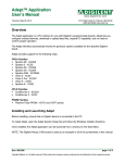
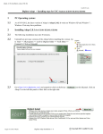
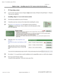
Digilent Adept Suite
User’s Manual
®
www .d ig ilen tinc .c om
Revision: 11/30/06
215 E Main Suite D | Pullman, WA 99163
(509) 334 6306 Voice and Fax
Overview
To install the Digilent Adept Suite, open the Adept Setup file and follow the Windows Installer
directions.
The Digilent Adept Suite consists of four tools:
•
ExPort programs Xilinx FPGAs, CPLDs, and PROMs using a JTAG connection.
•
TransPort enables data transfer with the FPGA on a connected system board.
•
Ethernet Administrator configures the Net1 module firmware.
•
USB Administrator displays connected USB modules, cables, and onboard USB.
Features include:
•
•
•
•
JTAG configuration of Xilinx logic devices with USB (v2.0) and Ethernet (DHCP compatible)
capabilities
data transfer with Xilinx FPGAs
configuration of Xilinx FPGA, CPLD, and PROM families
compatiblity with .bit, .jed, .mcs, and .svf configuration files
The JTAG Scan Chain
The Joint Test Action Group (JTAG) standard is used by many chip manufacturers to program logic
memory devices. JTAG is specified by IEEE 1149.1. A device is JTAG compliant if it contains a JTAG
TAP controller as well as TDI, TDO, TMS, and TCK pins. The TDI inputs data into the JTAG TAP
controller and the TDO provides outputs. Any FPGA, CPLD, or PROM that is JTAG-compliant can be
erased, programmed, and verified using this standard.
The TDI and TDO pins on several JTAG devices can be connected together to form a JTAG scan
chain. To program a device in the JTAG scan chain, all other devices are set to BYPASS, so they are
ignored and not configured. Then a series of bits are shifted into the scan chain (through TDI) to
configure the device. This is how ExPort programs devices.
JTAG Scan Chain
Doc: 506-000
page 1 of 13
Copyright Digilent, Inc. All rights reserved. Other product and company names mentioned may be trademarks of their respective owners.
Digilent, Inc.
Digilent Adept Suite User’s Manual
www.digilentinc.com
Communication Modules
ExPort communicates with configurable devices via communication modules such as peripheral
boards, cables, and on-board USB circuitry on system boards. Communication modules that can be
used with ExPort include:
•
•
•
•
USB Cable (USB-JTAG)
USB Module (USB2)
Ethernet Module (Net1)
JTAG3 Parallel Cable
ExPort
The ExPort application programs Xilinx FPGAs, CPLDs, and PROMs.
The Adept Suite keeps track of communication modules in a list called the device table. A device
must be added to this list before ExPort can connect to it. If using a single Digilent USB device, one
can automatically connect to it using the auto-detect feature by checking the Auto-Detect USB
checkbox.
Digilent ExPort Main Window
www.digilentinc.com
page 2 of 13
Copyright Digilent, Inc. All rights reserved. Other product and company names mentioned may be trademarks of their respective owners.
Digilent Adept Suite User’s Manual
Digilent, Inc.
www.digilentinc.com
Connecting to the Scan Chain
To access the device table, click Configure in the Connection dialog box and the Communication
Modules dialog box appears.
To Add an Ethernet Module
After opening the Communication Modules dialog box, click Add Module. The Add Module dialog box
appears.
www.digilentinc.com
page 3 of 13
Copyright Digilent, Inc. All rights reserved. Other product and company names mentioned may be trademarks of their respective owners.
Digilent Adept Suite User’s Manual
Digilent, Inc.
www.digilentinc.com
At the top of the dialog box there are two tabs, the Ethernet tab and the USB tab. Select the Ethernet
tab and enter a device name. This device name is used to locate the device in the table. The name
is not the device ID and is not used to connect to the firmware on the device.
If the Ethernet module is on the subnet, click Find Modules. A dialog box appears to the right of the
Add Module dialog box. All modules on the subnet that have not been included in the device table will
be found and posted in the dialog box. To add a found device, select it in the list box and click Add.
To add an Ethernet module that is not connected to the subnet, enter a selection string (the device’s
ID, IP address, or serial number), and click Add.
Save changes to the device table before closing the Communication Modules dialog box.
To Add a USB Device
After opening the Communication Modules dialog box, click Add Module. The Add Module dialog box
appears.
Click the USB tab and enter a device name. All Digilent USB devices connected to the PC are shown
in the list box. Select the USB device and click Add. Save changes to the table before closing the
Communications dialog box.
www.digilentinc.com
page 4 of 13
Copyright Digilent, Inc. All rights reserved. Other product and company names mentioned may be trademarks of their respective owners.
Digilent Adept Suite User’s Manual
Digilent, Inc.
www.digilentinc.com
Initializing a Scan Chain
ExPort must find all devices in a scan chain before it can program a JTAG device. The scan chain is
initialized when JTAG devices are found and displayed. To initialize the JTAG scan chain, select a
module in the Connections dialog box and click Initialize Scan Chain. If a valid scan chain is found, it
is initialized and displayed in the Scan Chain window.
If ExPort is unable to connect to the selected communication module, an error message appears. If
ExPort is able to connect to the module, but is unable to find a valid scan chain, the Scan Chain
window remains empty. ExPort does not recognize or program non-Xilinx JTAG devices.
NOTE: If the system board has “cable bypass” stenciled near the TDI or TDO pins, short the pins
when not using the JTAG port.
Programming Devices in ExPort
To program a device in the JTAG scan chain with a configuration file, click Browse next to the device
icon in the Scan Chain window. Select the appropriate configuration file in the Open dialog box and
press Open. If the file has already been added, select the file in the pull-down box to the left of the
Browse button. It shows all the files that have been added in the Configuration Files list box.
To program the device, right-click on the device icon in the Scan Chain window and select Program
Device.
To program every device in the JTAG scan chain, click Program Chain in the main window. Every
non-bypassed device with an assigned configuration file will be programmed from first to last in the
chain.
NOTE: Most PROMS require a long time to erase. ExPort may appear to have frozen while
attempting to program a PROM using an .svf file. This is normal, and can take up to 30 seconds.
Descriptions of All Commands in ExPort
File Menu
Add File Adds a file to the Configuration Files list. Once added, this file can be associated with a
device in the JTAG scan chain.
Remove File Removes a file from the Configuration Files list.
Exit Exits the ExPort tool.
www.digilentinc.com
page 5 of 13
Copyright Digilent, Inc. All rights reserved. Other product and company names mentioned may be trademarks of their respective owners.
Digilent Adept Suite User’s Manual
Digilent, Inc.
www.digilentinc.com
Edit Menu
Configure Communication Modules Opens the Communication Modules dialog box. Devices in
the device table can be added, deleted, or modified in this dialog box.
Clear Message Window Clears all text in the message window.
Copy Copies selected text in the message window.
Select All Selects all text in the message window.
Control Menu
Initialize Scan Chain Initializes a scan chain using the selected communication module. If devices
are found, the JTAG Scan Chain window is populated with them.
Program Scan Chain Programs all devices in the scan chain. A device will only be programmed if it
is not bypassed and has a valid configuration file associated with it.
Program Device Programs the selected device in the scan chain.
Erase Device Erases the selected device in the scan chain for supported PROMs and CPLDs.
Get Device ID Gets the JTAG IDCODE of the selected device. The IDCODE is displayed in the
message window.
Loop Device ID Performs the Get Device ID operation a specified number of times.
Help Menu
About ExPort Shows version information about ExPort.
Help Shows users manual.
TransPort
The TransPort tool allows for communication and data transfer with a properly configured FPGA.
Getting Started
Before TransPort can be used, the FPGA must be configured to read and write data to specific
registers. Several reference designs are provided in the Digilent reference designs directory.
www.digilentinc.com
page 6 of 13
Copyright Digilent, Inc. All rights reserved. Other product and company names mentioned may be trademarks of their respective owners.
Digilent Adept Suite User’s Manual
Digilent, Inc.
www.digilentinc.com
After opening TransPort, click the Properties tab to specify the communication module and
handshaking options. To add devices to the device table, click Configure in the Connections box.
The handshaking options are not available in this version of Adept.
All values can be entered as binary, decimal, or hexadecimal. For example, a binary byte is entered
10101010, a decimal byte is written as 170, and a hexadecimal byte as 0xaa.
Loading or Streaming a File into a Register
To load data from a file, click the Load File tab.
Choose a file along with the start location for reading from the file. Enter the register to be loaded,
and the number of bytes to be read from the file. To load all bytes from the specified file, check Load
Entire File. Finally, click Load to start the transaction.
Storing or Streaming a File into a Register
To store a file, click the Store File tab.
www.digilentinc.com
page 7 of 13
Copyright Digilent, Inc. All rights reserved. Other product and company names mentioned may be trademarks of their respective owners.
Digilent Adept Suite User’s Manual
Digilent, Inc.
www.digilentinc.com
Choose a file to store the streaming data from the register. The file can be written to in three different
ways:
• Append the data stream to an existing file.
• Destroy all existing data and replace it with data stream.
• Overwrite data in the file starting at a specified location.
Enter the register to be read from, and the number of bytes to be read from it. Finally, click Store to
start the transaction.
Reading or Writing Registers
Click the Register I/O tab.
www.digilentinc.com
page 8 of 13
Copyright Digilent, Inc. All rights reserved. Other product and company names mentioned may be trademarks of their respective owners.
Digilent Adept Suite User’s Manual
Digilent, Inc.
www.digilentinc.com
To read data out of a register, enter a 1-byte address, and click the corresponding Read button. The
data read from the register will appear in the text box to the right of the button.
To write data into a register, enter a 1-byte address, the byte to write to the register, and click the
corresponding Write button. To read or write data to a group of addresses, enter all the needed
information and then click Read All or Write All.
Ethernet Administrator
The Digilent Ethernet Administrator (DEA) is used to configure the firmware on the Ethernet modules.
Ethernet modules are shipped with a default IP address, subnet mask, default gateway address,
device ID string, and DHCP setting. Although every Ethernet module has the same default settings,
each has a unique, 12-digit hexadecimal serial number (or MAC address).
The IP address, subnet mask, and device ID string must be changed using the Ethernet Administrator
before an Ethernet module can be used with ExPort.
Using Ethernet Administrator
Before opening Ethernet Administrator, connect all Ethernet modules to system boards (this provides
power to the modules). Connect the modules to the same subnet as the PC that will be running
Ethernet Administrator. If only one board is being configured, a crossover Ethernet cable can be used
to connect the board directly to the PC. Once the system boards are connected Ethernet
Administrator can be used.
When Ethernet Administrator is opened, the main window appears.
www.digilentinc.com
page 9 of 13
Copyright Digilent, Inc. All rights reserved. Other product and company names mentioned may be trademarks of their respective owners.
Digilent Adept Suite User’s Manual
Digilent, Inc.
www.digilentinc.com
To Find Modules
First, click Find to find all modules on the subnet. If all of the modules are not found, make sure all
modules are receiving power and click Find again. If still unable to find a specific module, reset the
module by shorting the Reset jumper (see the Ethernet Module Reference Manual). The Find
operation can be stopped at any time by clicking Stop Find.
To Configure Modules
There are two ways to configure Ethernet modules. Each module can be configured separately, or
modules can be configured at the same time using Auto Configure.
Single Module Configuration
To configure a single module, select the module and click Configure. The Configure dialog box
appears.
The module’s current settings are displayed in the dialog box. If the setting is activated (by clicking on
the check box to the left of the setting), it will be modified. After all desired settings have been
modified, click Configure to configure the settings on the module’s firmware. If successful, the dialog
box closes.
WARNING: It is possible to set the subnet mask and IP address to invalid values that make it
impossible to connect to a module without resetting it. See “Setting Up Correct IP Addresses” below,
for more information.
www.digilentinc.com
page 10 of 13
Copyright Digilent, Inc. All rights reserved. Other product and company names mentioned may be trademarks of their respective owners.
Digilent Adept Suite User’s Manual
Digilent, Inc.
www.digilentinc.com
Multiple Module Auto Configuration
There are three ways to use Auto Configure:
•
•
•
Several devices in the main dialog box can be selected and configured simultaneously.
All devices in the main dialog box can be configured.
Automatically find and then configure all devices. This is useful when configuring a large
number of devices.
To select more than one device in the dialog box, hold the Shift key and select the desired devices.
Then, click Auto Configure. The Auto Configure dialog box appears.
The Auto Configure dialog box allows multiple boards to be configured from initial values. Ethernet
Administrator attempts to load the IP address, subnet mask, and default gateway address from the
PC’s primary Ethernet card. The Start IP Address setting is incremented by one for each board
configured. For example, when auto configuring four boards with the start IP address of
192.168.1.23, the following IP addresses would be generated and stored in the boards:
192.168.1.23
192.168.1.24
192.168.1.25
192.168.1.26
www.digilentinc.com
page 11 of 13
Copyright Digilent, Inc. All rights reserved. Other product and company names mentioned may be trademarks of their respective owners.
Digilent Adept Suite User’s Manual
Digilent, Inc.
www.digilentinc.com
The device ID must be unique for each module. This is accomplished by putting symbols into the ID
string that are replaced with unique values. There are two different ways to do this.
•
•
Insert # into the ID string to put a sequence number digit into the ID string.
Insert % into the ID string to put the lowest significant serial number digit into the ID string.
These symbols can be used repeatedly throughout the ID string and are interchangeable. If a
sequence number is used, a starting sequence number must be specified in the Sequence Number
Start text box. Unlike the ID string and IP address, the subnet mask, default gateway, and DHCP
setting remain constant during the auto configuration process.
Setting Up Correct IP Addresses
Before Ethernet Administrator configures a device, it checks the compatibility of the entered IP
address and subnet mask. However, it cannot check if the IP address entered conflicts with the
current subnet. The subnet mask entered must be identical to the one on the current subnet.
If an IP address is set to the broadcast or subnet address, the board will no longer be able to
communicate with the Ethernet Administrator. The Ethernet module must be reset to factory settings
if this occurs. See the Ethernet Module Reference Manual for more information.
When creating an IP address, make sure it does not conflict with the IP address of an existing
Ethernet device on the subnet (such as another computer, printer, etc.) This can be solved if a DHCP
server is placed on the subnet. When an Ethernet module is configured to use DHCP, it will be
assigned a valid IP address from the DHCP server.
For more detailed information on IP address and Subnet mask assignment, see the sources listed
under ”References”, below.
USB Administrator
The Digilent USB Administrator (DUA) is used to view all of the attached Digilent USB devices. After
opening DUA, a list of all Digilent USB devices connected to the PC appears.
Troubleshooting
ExPort
If ExPort is unable to communicate with a Digilent USB device…
•
•
•
•
Close Export
Verify that Xilinx ISE/Webpack is installed on the computer, and that the Xilinx environmental
variable properly points the Xilinx install point.
Make sure the latest version of ExPort is installed.
Make sure the USB cable is securely attached to the circuit board and PC (unplug and
reattach both ends of the cable)
www.digilentinc.com
page 12 of 13
Copyright Digilent, Inc. All rights reserved. Other product and company names mentioned may be trademarks of their respective owners.
Digilent Adept Suite User’s Manual
•
•
•
Digilent, Inc.
www.digilentinc.com
After the USB cable is reattached, wait for the PC to identify the cable and follow prompts as
they appear
Restart Export
Note: Some Digilent boards have special requirements for using the USB-JTAG port (for
example, the X-board has a switch that maps the programming port to an A/D converter).
Please refer to the “Configuration” section of the circuit board’s reference manual for more
information about specific board issues.
If ExPort is unable to communicate with a Digilent Ethernet device…
•
•
•
•
Make sure that the communication module is correctly connected to the circuit board and
entered into the device table.
Make sure the Ethernet cable is securely attached to the circuit board and PC (unplug and
reattach both ends of the cable and the module itself).
If the selected communication module is an Ethernet module, make sure that it has been
configured using Ethernet Administrator.
Make sure the latest version of ExPort is installed.
Ethernet Administrator
If Ethernet Administrator cannot find any or all of the devices on the subnet…
•
•
•
Make sure all Ethernet modules are receiving power and are properly connected to the subnet.
Click the find button again. Due to network traffic and packet collision, some devices may be
slow to receive packets.
If a certain device continues to not be found, short the configure reset pins with a jumper. This
will return its firmware settings to default.
References
Maufer, Thomas A. IP Fundamentals, Prentice Hall 1999
Stevens, Richard W. TCP/IP Illustrated, Volume1: The Protocols. Addison Wesley 1994
www.digilentinc.com
page 13 of 13
Copyright Digilent, Inc. All rights reserved. Other product and company names mentioned may be trademarks of their respective owners.