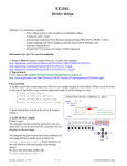
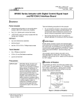
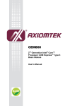
1
Adept™ Application
User’s Manual
Revision: May 28, 2010
®
ww w. d ig i l en t inc .c om
215 E Main Suite D | Pullman, WA 99163
(509) 334 6306 Voice and Fax
Overview
The Adept application is a PC interface for use with Digilent’s programmable boards. Adept lets you
configure onboard devices, download or upload data files, expand I/O capability, and run tests to
confirm proper operation.
The Adept interface automatically shows the particular options available for the attached Digilent
board.
Adept provides support for the following chips.
FPGA Families
• Spartan 2E - XC2SE
• Spartan 3 - XC3S
• Spartan 3E - XC3SE
• Spartan 3A - XC3SA
• Spartan 3AN - XC3SAN
• Virtex 2 - XC2V
• Virtex 2 Pro - XC2VP
• Virtex 5 – XC5V
• Spartan 6 – XC6S
CPLD Families
• CoolRunner 2 - XC2CA
• CoolRunner 2 - XC2C
PROM Families
• Platform Flash PROM - XCFS (not XCFP series)
Installing and Launching Adept
Before installing, ensure that no Digilent device is connected to the PC.
To install Adept, open the Adept System Setup file and follow the Windows Installer directions.
Once installed, the Adept application can be launched from a shortcut in the Start Menu.
NOTE: The Digilent Nexys 2-500 board is used as an example in all of the screenshots in this manual.
Doc: 506-009
page 1 of 9
Copyright Digilent, Inc. All rights reserved. Other product and company names mentioned may be trademarks of their respective owners.
Digilent Adept User’s Manual
Digilent, Inc.
www.digilentinc.com
The Config Tab
When you launch Adept, it connects to the first Digilent product it finds (or the last one selected) and
attempts to initialize itself for device configuration. Most Digilent products contain device configuration
capabilities, so the Config (configuration) tab is usually shown by default. Any configurable devices
are listed in the Config tab.
To initialize Adept for device programming:
1. Select a product in the Connect drop-down list box.
2. Adept tries to initialize itself for device configuration. It can be manually initialized by clicking
the Initialize button.
3. After initializing, the Adept interface shows the available configuration options for the attached
device in the drop-down list box next to the device icon.
4. If Adept is unable to connect to the product, or is unable to initialize, the window displays “No
devices identified.” If this happens, try disconnecting and then reconnecting the product.
To program a device:
1. Click the Browse button next to the device icon in the window. An Open dialog box appears.
2. Select the appropriate configuration file in the Open dialog box and click the Open button.
Adept displays a history of configuration files in the drop-down list box next to the device.
3. Click the Program button or right-click on the device icon and select Program Device.
www.digilentinc.com
page 2 of 9
Copyright Digilent, Inc. All rights reserved. Other product and company names mentioned may be trademarks of their respective owners.
Digilent Adept User’s Manual
Digilent, Inc.
www.digilentinc.com
Choosing Other Device Configuration Operations
Some devices can be erased, verified, or have their JTAG ID codes looped for connection strength
verification. These operations can be started by right-clicking on the device icon.
The Test Tab
Adept can run simple diagnostic tests on some boards so that you can verify that the board is
functioning properly.
To begin a test of the board, click the Start Test button. This automatically loads a diagnostic test
configuration to the FPGA (or other logic device).
While the test is active, the board’s button and switch status is displayed to help identify any failing I/O
component. For some boards (like the Nexys2), automated onboard memory tests are provided. In
the Nexys2 example above, clicking the Test RAM and Test Flash buttons runs a walking ‘1’ test
through the respective memory device to verify proper operation.
The test can be stopped any time by pressing the Stop Test button, switching to a different tab, or
changing the connected device.
www.digilentinc.com
page 3 of 9
Copyright Digilent, Inc. All rights reserved. Other product and company names mentioned may be trademarks of their respective owners.
Digilent Adept User’s Manual
Digilent, Inc.
www.digilentinc.com
The Register I/O Tab
Adept supports PC communication with system boards via a register-based transfer system,
assuming that the FPGA (or logic device) has an EPP-style interface (as outlined in the DpimRef
Programmer’s Reference Manual on the Adept web page). Using the Register I/O tab, you can read
or write a register value on the system board by specifying a register address.
To read data out of a register, enter a 1-byte address, and click the corresponding Read button. The
data read from the register will appear in the Data text box to the left of the button.
To write data into a register, enter a 1-byte address, enter the byte to write to the register in the Data
text box, and click the corresponding Write button.
To read or write data to a group of addresses, enter all the needed information and then click Read All
or Write All.
All values can be entered as binary, decimal, or hexadecimal using the following formats:
•
•
•
a binary byte: 10101010
a decimal byte: 170
a hexadecimal byte: 0xaa.
www.digilentinc.com
page 4 of 9
Copyright Digilent, Inc. All rights reserved. Other product and company names mentioned may be trademarks of their respective owners.
Digilent Adept User’s Manual
Digilent, Inc.
www.digilentinc.com
The File I/O Tab
You can transfer partial or entire files to or from the system board using the File I/O tab, assuming that
the FPGA (or logic device) has an EPP-style interface (as outlined in the DpimRef Programmer’s
Reference Manual found on the Adept web page).
To upload or stream a file into a register:
1. Choose a file along with the start location for reading from the file.
2. Enter the register address to be uploaded to, and the length in bytes to be read from the file
(the entire file can be uploaded by clicking the check-box under Upload).
3. Click the File >> Device button to start the transaction.
To download or stream a file from a register:
1. Choose a file to download the streaming data from the register. The file can be written to in
three different ways:
• Append the data stream to an existing file.
• Destroy all existing data and replace it with data stream.
• Overwrite data in the file starting at a specified location.
2. Enter the register to be read from, and the length in bytes to be read from it.
3. Click the File << Device button to start the transaction.
www.digilentinc.com
page 5 of 9
Copyright Digilent, Inc. All rights reserved. Other product and company names mentioned may be trademarks of their respective owners.
Digilent Adept User’s Manual
Digilent, Inc.
www.digilentinc.com
The I/O Ex Tab
You can control the system board using the expanded virtual I/O controls on the I/O Ex tab, assuming
that the FPGA (or logic device) has an EPP-style interface (as outlined in the I/O Ex Programmer’s
Reference Manual found on the Adept web page). The expanded I/O controls include 16 switches, 16
buttons, 8 LEDs, 24 individual light bars, and the ability to send and receive a 32-bit value.
Adept connects to the I/O Ex configuration when you press the Start I/O button. A special
handshaking register is checked to verify that the I/O Ex design is active in the FPGA. If it is valid, the
I/O Ex status light turns green. If it isn’t, the light turns yellow, but the I/O registers are still polled.
The I/O Ex connection can be stopped any time by pressing the Stop I/O button, switching to a
different tab, or changing the connected device.
Switches are flipped and buttons pressed by clicking on the graphics. If any error occurs while
reading the status of these controls, they will be disabled for the duration of the I/O Ex connection.
www.digilentinc.com
page 6 of 9
Copyright Digilent, Inc. All rights reserved. Other product and company names mentioned may be trademarks of their respective owners.
Digilent Adept User’s Manual
Digilent, Inc.
www.digilentinc.com
Sending a Value to the FPGA
A 32-bit value can be entered as a decimal, signed decimal, hexadecimal, or binary value. Click the
Send button to send this value to the FPGA (or logic device).
All values can be entered as binary, decimal, or hexadecimal using the following formats:
•
•
•
•
a binary byte: 0b10101010101010101010101010101010
a decimal byte: 2863311530
a hexadecimal byte: 0xaaaaaaaa
a signed decimal byte: -1
Receiving a Value from the FPGA
A 32-bit value is constantly polled from the FPGA (or logic device).
The Settings Tab
The Settings tab lets you change various options. For example, you can set Adept to operate in Slow
Programming Speed mode.
The Settings tab also lets you access the Device Table Manager.
www.digilentinc.com
page 7 of 9
Copyright Digilent, Inc. All rights reserved. Other product and company names mentioned may be trademarks of their respective owners.
Digilent Adept User’s Manual
Digilent, Inc.
www.digilentinc.com
The Device Table Manager
The Device Table Manager provides a way to add or remove Digilent products to and from a Device
Table. It is launched by clicking the Device Table Manager button in the Settings tab.
To see the devices that are connected, click the Enumerate button. Clicking on an enumerated
device will automatically write the serial number to the Connect text box. Use the Alias text box to
enter a custom name for your device. The alias is displayed the Connect drop-down list box in Adept.
After assigning an Alias, click the Add Dvc button to add the device to the device table.
To remove a device from the device table, click the Remove Dvc button.
To save the current state of the Device table, click the Save button before exiting.
www.digilentinc.com
page 8 of 9
Copyright Digilent, Inc. All rights reserved. Other product and company names mentioned may be trademarks of their respective owners.
Digilent, Inc.
Digilent Adept User’s Manual
www.digilentinc.com
Appendix A: The JTAG Scan Chain
The JTAG (Joint Test Action Group) standard is used by many chip manufacturers to program logic
memory devices. JTAG is specified by IEEE 1149.1. A device is JTAG-compliant if it contains a
JTAG TAP controller as well as TDI, TDO, TMS, and TCK pins. The TDI inputs data into the JTAG
TAP controller and the TDO provides outputs. Any FPGA, CPLD, or PROM that is JTAG-compliant
can be erased, programmed, and verified using this standard.
The TDI and TDO pins on several JTAG devices can be connected together to form a JTAG scan
chain. To program a device in the JTAG scan chain, all other devices are set to BYPASS, so they are
ignored and not configured. Then a series of bits are shifted into the scan chain (through TDI) to
configure the device.
JTAG Scan Chain
www.digilentinc.com
page 9 of 9
Copyright Digilent, Inc. All rights reserved. Other product and company names mentioned may be trademarks of their respective owners.