1
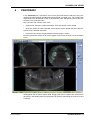
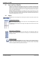
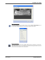
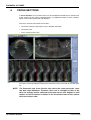
EN
3D Viewer
user's manual
10017352_2
PLANMECA 3D VIEWER
TABLE OF CONTENTS
1
SYSTEM REQUIREMENTS ....................................................................................................................... 1
2
STARTING PLANMECA 3D VIEWER ....................................................................................................... 2
3
PLANMECA 3D VIEWER INTRODUCTION ............................................................................................. 3
3.1
4
5
6
Menu Toolbar ............................................................................................................................... 4
EXPLORER ............................................................................................................................................. 6
4.1
3D Volume Viewing ..................................................................................................................... 6
4.2
3D Volume Aspects ..................................................................................................................... 7
4.3
Rendered Volume Auxiliaries (Vertical Toolbar) .......................................................................... 7
4.4
Layer Slide Bar and Maximize ..................................................................................................... 8
4.5
Volume Adjustments .................................................................................................................... 8
PANORAMIC ...................................................................................................................................... 11
5.1
Layer and Curve Slide Bar ......................................................................................................... 12
5.2
Adjust ......................................................................................................................................... 12
5.3
Panoramic .................................................................................................................................. 14
CROSS SECTIONS ............................................................................................................................... 16
6.1
Cross Sectional Slide Bar .......................................................................................................... 17
6.2
Adjust ......................................................................................................................................... 17
6.3
Panoramic .................................................................................................................................. 18
6.4
Cross Sections ........................................................................................................................... 20
6.5
Nerve ......................................................................................................................................... 20
The manufacturer, assembler, and importer are responsible for the safety, reliability and
performance of the unit only if:
- installation, calibration, modification and repairs are carried out by qualified
authorized personnel
- electrical installations are carried out according to the appropriate requirements such
as IEC364
- equipment is used according to the operating instructions
Planmeca pursues a policy of continual product development. Although every effort is
made to produce up-to-date product documentation this publication should not be
regarded as an infallible guide to current specifications. We reserve the right to make
changes without prior notice.
COPYRIGHT PLANMECA 2008-03
PUBLICATION PART NUMBER 10017352 Revision 2
User’s manual
Planmeca Romexis 1
TABLE OF CONTENTS
2 Planmeca Romexis
PLANMECA 3D VIEWER
User’s manual
PLANMECA 3D VIEWER
PLANMECA 3D VIEWER
Planmeca 3D Viewer is a freely distributable viewer software for Planmeca 3D DICOM
files (*.dcm). It has the ability to read DICOM Multiframe images stored in the same folder
displaying the slice views, rendered presentation, panoramic and cross sections view.
This manual describes Planmeca 3D Viewer system requirements and contains user
instructions for the software.
1
SYSTEM REQUIREMENTS
Planmeca 3D Viewer runs on Java JRE 1.6 compatible operating systems, such as Microsoft Windows (MacOS and Linux).
Recommendation for Planmeca 3D Viewer hardware is 1GHz processor, 2GB RAM, 80
MB local disk storage for the Planmeca 3D Viewer software and 250 MB per 3D image.
3D rendering requires a compatible graphics card. Note also that 2GB RAM is the minimum recommendation for a smooth viewing of 3D volumes.
NOTE Planmeca 3D Viewer has been tested with Windows Vista, Windows XP SP 2
and MacOS X 10.4. Therefore, other operating systems are not supported by
Planmeca.
User’s manual
Planmeca Romexis 1
PLANMECA 3D VIEWER
2
STARTING PLANMECA 3D VIEWER
Windows operating system
• Insert the Viewer CD into the CD-ROM drive*:
The Planmeca 3D Viewer Launcher starts up automatically.
•
Choose an image from the image list under Patient Name and click Start viewer**.
MacOS X
•
Insert the CD into the CD-ROM drive*.
•
Start the Planmeca 3D Viewer by double-clicking the Viewer for MAC application icon.
*For an optimal experience you can copy the CD to the local hard disk and start it from
there. Place the exported DICOM files to the same folder.
**OpenGL rendering can be selected for a better rendering experience with a compatible
graphics card.
View Romexis 3D Demo Show (available only on demo CDs)
You can use the Planmeca 3D Viewer for demonstration purposes by clicking Start
Demo.
2 Planmeca Romexis
User’s manual
PLANMECA 3D VIEWER
3
PLANMECA 3D VIEWER INTRODUCTION
The layout of Planmeca 3D Viewer is divided into three parts:
1. Menu: Toolbar on the top.
2. 3D Volume Viewing: Main part of the Planmeca 3D Viewer with the view display.
3. Volume Adjustments: Located on the right, containing the image processing tools.
The menu toolbar functionality is explained in chapter 3.1 “Menu Toolbar” on page 4. 3D
volume viewing and volume adjustments depend on the view selected, and they are
explained in their own chapters, see 4.1 “3D Volume Viewing” on page 6 and 4.2 “3D Volume Aspects” on page 7.
Additionally, the Viewer can display three different views:
1. Explorer: sagittal, coronal, axial and rendered view (see 4 “EXPLORER” on page 6)
2. Panoramic: panoramic view and curve (see 5 “PANORAMIC” on page 11)
3. Cross sections: cross sectional slices and nerve drawing (see 6 “CROSS SECTIONS”
on page 16)
User’s manual
Planmeca Romexis 3
PLANMECA 3D VIEWER
3.1
Menu Toolbar
The Planmeca 3D Viewer menu toolbar contains buttons common to all Planmeca 3D
Viewer tabs. Functions available on this toolbar include volume adjustments, measurements, saving of 3D views, reset view and zoom.
Adjust Levels
If the adjustment of the sliced views is not satisfactory, the adjustments can be done manually by using the Adjust Levels window. The gamma curve can be adjusted by moving the
green line in the histogram. The value can be seen in the box in the middle of the window.
The histogram can also be cut from both sides by moving the red lines, which affects the
adjustment of contrast and brightness.
By clicking the arrows in the middle the histogram can be scaled up or down. The button
restores the original scale of the histogram.
NOTE
A histogram is a graphic representation of the intensity distribution in the
volume.
Measure Length
Click the icon and draw the line by holding the left mouse button down. End the line with a
double-click (or with a right-click).
Measure Angle
Click the icon to draw an angle into a sliced view by holding the left mouse button down.
Drag to draw the first line and then click and drag to draw the second line.
Save Current View
Saves the view currently displayed. Enter a name into the opening dialog.
Select a Saved View
Selects one of the saved views from a list.
4 Planmeca Romexis
User’s manual
PLANMECA 3D VIEWER
Delete a View from the Saved Views
Deletes one of the saved views from a list.
Reset View to Default Orientation
Restores the original adjustments of the views.
Show/Hide Orientation Lines
Shows and hides the orientation lines of the sliced views.
All views have orientation lines to facilitate the comprehensive view and the relation to
each other. This means, for example, that the view of the coronal plane is indicated with a
green line in the sagittal plane, axial plane and with a green auxiliary plane in the perspective view. Likewise the sagittal and axial planes are indicated. With the Rendered Volume
Auxiliaries icons you can switch the auxiliary lines in the rendered volume on or off.
Zoom Mode
When the Zoom Mode icon in the menu toolbar is activated the sliced views can be scaled
up or down. Move the mouse pointer over the desired view and turn the mouse wheel into
the appropriate direction.
DICOM images drop-down list
The top part of the Planmeca 3D Viewer also contains a drop-down list of the DICOM
images located in the Planmeca 3D Viewer folder. By clicking the image list drop-down
button, a list of all the 3D volumes in shown.
View
A 3D volume can be opened by selecting an image from the drop-down list and clicking
the View button.
Properties
By clicking the Properties button, you can see the properties of the image selected from
the drop-down list.
User’s manual
Planmeca Romexis 5
PLANMECA 3D VIEWER
4
EXPLORER
In the Explorer tab the existing 3D volumes can be opened and adjusted as well as
viewed in three different directions.
4.1
3D Volume Viewing
The 3D volume is displayed simultaneously in four different views: Sagittal (red), Coronal
(green), Axial (blue) and 3D rendered view. The red, blue and green lines across the views
indicate the slicing planes in the views.
The position in the volume can be freely adjusted by holding down the left mouse button
and moving the mouse in the view. All views are connected to each other, which means
that moving one view will affect the other views as well, except for the rendered volume.
While moving the mouse on one view the two other views automatically move to the
corresponding position. The viewing angle can be rotated freely by holding down the right
mouse button while moving the mouse.
When orienting the image, you can recognize anterior, posterior, left, and right anatomies
by the A/P/L/R letters respectively on the edges of the views. These will automatically
update to denote the nearest anatomy to the edge.
When moving the mouse cursor on top of the image, a Hounsfield Unit (HU) value will be
shown at the bottom right of the current view. The value shown is an average value of 3 x
3 pixel area under the mouse cursor.
6 Planmeca Romexis
User’s manual
PLANMECA 3D VIEWER
4.2
3D Volume Aspects
Clicking the 3D Volume Aspects icons provides a 180° degrees rotation of a specific
view. The modification of the aspect in one of the views also changes the aspect of the
rendered volume.
Anterior view of the plane.
Posterior view of the plane.
Lateral view of the plane.
Contralateral view of the plane.
Upper view of the plane.
Exterior view of the plane.
4.3
Rendered Volume Auxiliaries (Vertical Toolbar)
The rendered volume view in the bottom right corner of the Planmeca 3D Viewer has three
auxiliary planes, indicating the coronal, sagittal and the axial planes. By means of these
planes the three views are easily allocated in the volume. To show or hide the auxiliary
planes in the rendered volume click the correlating icons at the right side of the rendered
volume view:
Show Coronal Plane
Show Sagittal Plane
Show Axial Plane
Show / Hide All Planes
Furthermore, the rendered volume is surrounded by a volume boundary. To show/hide
the volume boundary click the
Rendering
icon. By clicking the Show Perspective in 3D
icon, the rendered volume is displayed in a linear perspective, which
results in a natural image impression.
User’s manual
Planmeca Romexis 7
PLANMECA 3D VIEWER
Show/Hide Orientation Lines
Shows and hides the orientation lines of the sliced views.
All views have orientation lines to facilitate the comprehensive view and the relation to
each other. This means, for example, that the view of the coronal plane is indicated with a
green line in the sagittal plane, axial plane and with a green auxiliary plane in the perspective view. Likewise the sagittal and axial planes are indicated. With the Rendered Volume
Auxiliaries icons you can switch the auxiliary lines in the rendered volume on or off.
4.4
Layer Slide Bar and Maximize
Clicking the Maximize
icon in the top right corner of the relating view opens a full
sized window, showing the image.
At the right border of each view, the coronal, sagittal and axial views, is a layer slide bar. In
each case the slide bar can be moved to scroll through the image layers of the corresponding view. For example, scrolling the slide bar of the coronal view moves the view
inside the layers forward or backwards. The corresponding orientation lines in the two
other views as well as the auxiliary plane in the 3D rendered view automatically move to
the appropriate position.
NOTE
4.5
It is also possible to scroll through the image layers using the mouse wheel,
when the Zoom Mode is deactivated (see 4.5.1 “Adjust” on page 8).
Volume Adjustments
Volume Adjustments at the far right contains the image processing tools, explained in
more detail below.
4.5.1
Adjust
The Adjust tools can be applied on the slice views, meaning the coronal, sagittal and axial
view and enable the modification, examination and measurement of the views.
Thickness
Defines the displayed slice thickness of the slice views.
The resampling/thickness can be adjusted from the drop-down menu.
Adjust Contrast and Brightness
Regulates the contrast and brightness of the coronal, sagittal and axial view. By dragging
the sliders the brightness and the contrast can be adjusted.
8 Planmeca Romexis
User’s manual
PLANMECA 3D VIEWER
NOTE
When the Zoom Mode is deactivated the same action, turning the mouse
wheel over a view, will scroll through the image layers as the Layer Slide
Bars do (see 4.4 “Layer Slide Bar and Maximize” on page 8).
NOTE
The rendered volume can be zoomed with and without the Zoom Mode
activated.
Crop Volume for 3D Rendering
Crop Volume for 3D Rendering crops the rendered volume. It is applied to the sliced
views and affects only the 3D rendered volume view.
After clicking the Crop icon, move the mouse pointer on one sliced view. Press the left
mouse button and a white framed rectangle appears. By dragging the mouse on the view
the cropped area can be defined. The rectangle also appears at the two other sliced
views, to be able to define an exact area for the cropping. After selecting the area press
the right mouse button to start the cropping process.
Select Annotation(s)
Toggle editing mode for annotations and measurements. When active, select an annotation or measurement to bring up handles that can be used to edit the control points of the
selected item.
Export View to Other Tabs
Exports the currently displayed view of the slices to the Panoramic and Cross Sections
tabs. The processed slices are shown in the other tabs like in the Explorer.
4.5.2
3D Rendering
The 3D Rendering tools can be applied to manipulate the rendered volume.
Adjust Contrast and Brightness
Regulates the contrast and brightness of the rendered volume. By dragging the sliders the
brightness and the contrast can be adjusted.
Set 3D Rendering Cutoff Threshold
Moving the slider determines the threshold for which gray scale values are shown in the
3D rendered view.
Adjust 3D Rendering Transparency
Moving the slider to the top increases the transparency of the 3D rendered view.
User’s manual
Planmeca Romexis 9
PLANMECA 3D VIEWER
Adjust Levels
If the adjustment of the volume is not satisfactory, the adjustments can be done manually
by using the Adjust Levels window. The gamma curve can be adjusted by moving the
green line in the histogram. The value can be seen in the box in the middle of the window.
The histogram can be also cut from both sides by moving the red lines, which affects the
Adjustment of the Contrast and Brightness (see 4.5.1 “Adjust” on page 8).
Scale Histogram
By clicking the arrows in the middle, the histogram can be scaled up or down. The icon
restores the original scale of the histogram.
Threshold
The black line increases or decreases the threshold and consequently has the same function as the slider Set 3D Rendering Cutoff Threshold.
Pseudo Colour modification
The icons left and right of the gamma value, F and R, modify the pseudo colours. Clicking
the
icon alters and allocates the colour selection for different tissues automatically,
based on the curve of the histogram. To modify the pseudo colours manually, drag the
rectangles above the histogram left or right. With this, the position and range of the specific colour can be altered. By double-clicking the rectangle, the colours can be changed
for an individual selection. The
icon resets the modifications of the pseudo colours.
NOTE
A histogram is a graphic representation of the intensity distribution in the
volume.
Show Pseudo Colours in 3D Rendering
Clicking this icon changes the greyscale to colours. In the Adjust Levels window of the 3D
Rendering, the colours for the different tissues can be modified.
10 Planmeca Romexis
User’s manual
PLANMECA 3D VIEWER
5
PANORAMIC
In the Panoramic tab a panoramic view can be generated from the 3D data. The panoramic image generated can be adjusted and processed in multiple ways. The image range
and thickness can be defined as well as the selection of the appropriate curve for the construction of the panoramic view.
The Panoramic tab contains three views:
•
Sagittal view, where the sagittal orientation of the 3D volume can be rotated.
• Axial view, where the axial orientation of the volume can be rotated and where the panoramic curve is defined and shown.
•
Panoramic view, where the generated panoramic image is shown.
By turning the mouse wheel on top of the sagittal or axial view, the view can be zoomed in
or out.
Holding down the left mouse button while dragging the axial or sagittal view will move the
3D volume, and holding down the right button will rotate it. Refreshing the views may take
a moment.
User’s manual
Planmeca Romexis 11
PLANMECA 3D VIEWER
5.1
Layer and Curve Slide Bar
A slide bar is located at the right border of each view. In the sagittal and axial view the
slide bar can be moved to scroll through the image layers. This means that scrolling the
slide bar of the axial view up and down moves the view inside the layers forward or backwards. The corresponding orientation lines in the sagittal and panoramic view automatically move to reflect the changes.
Moving the slide bar of the panoramic view modifies the radius of the panoramic curve and
the change is immediately reflected in the axial view by the panoramic curve moving in or
out in relation to the patient’s anatomy. When the slider is released, the panoramic view is
automatically updated with the new curve.
5.2
Adjust
The Adjust tools at the top right of the Panoramic tab contains accessories to process the
views.
Defining the Slice Thickness
Defines the displayed slice thickness of the slice views. The resampling/thickness can be
adjusted from the drop-down menu.
The selections affects the display of the image in the sagittal and axial views, but not in the
panoramic view.
Adjust Contrast and Brightness
Regulates the contrast and brightness of the image views. By dragging the sliders, the
brightness and the contrast can be adjusted. The settings are saved automatically when
the image is closed.
Defining Data Range
By clicking the Define Data Range icon the area of interest for the panoramic image can
be defined. You can select from which part, lower or upper jaw, the panoramic image is
created. In the appearing window move the sliders up or down to adust. The left slider
restricts the upper jaw and the right slider the lower jaw.
12 Planmeca Romexis
User’s manual
PLANMECA 3D VIEWER
Show / Hide Settings
To set up the display of the orientation overlays, click the Show / Hide Settings icon. In
the Show/Hide Settings window you can select the overlays to be shown.
Select Annotation(s)
Use the Select Annotation(s) tool to toggle editing mode for annotations and measurements. When active, select an annotation or measurement to bring up handles that can be
used to edit the control points of the selected item.
User’s manual
Planmeca Romexis 13
PLANMECA 3D VIEWER
5.3
Panoramic
With the Panoramic imaging tools, the panoramic view can be defined and adjusted by
drawing a curve to the axial view and choosing a range to be displayed.
Draw Panoramic Curve
Romexis automatically places the panoramic curve. To define a new curve, click the Draw
Panoramic Curve icon. Use the left mouse button to place points for the curve on the
axial view. When you are done, click the right mouse button and the new panoramic view
will be calculated.
NOTE
All created panoramic curves will be saved and listed in the Select
Panoramic Curve option.
Delete Current Panoramic Curve
Clicking the Delete Current Panoramic Curve icon deletes the panoramic curve currently
displayed. The standard curves are not deleted.
Edit Panoramic Curve
To edit the curve, click the icon and move single points in the curve or even the whole
curve by grabbing the green line of the curve. Change the position by dragging the points
or the entire curve with the left mouse button. To finish editing, click the icon again.
Select Panoramic Curve
Clicking this icon shows a list of all saved panoramic curves. All curves you draw are
saved and named with the date and time they were created. Click on an entry to recall and
apply that curve.
14 Planmeca Romexis
User’s manual
PLANMECA 3D VIEWER
Adjusting the Panoramic Layer Thickness
To adjust the panoramic layer thickness, drag the slider up or down.
Monitor the sagittal and axial views to see the anatomy included in the layer.
User’s manual
Planmeca Romexis 15
PLANMECA 3D VIEWER
6
CROSS SECTIONS
In Cross Sections, cross sectional slices can be created from the 3D data. A specific area
of the volume can be chosen and displayed in a predefined number of cross sections,
which can be further processed and adjusted.
The Cross Sections tab contains three views:
•
Axial view, where the panoramic curve is defined and shown
•
Panoramic view
•
Cross sectional slices view
The views can be expanded by clicking the small dual arrows in the ends of the view dividers.
NOTE
The Panoramic and Cross Section tabs share the same panoramic curve
and data range definition. Therefore, when one is changed in either of the
tabs, the changes will be reflected in the other tab as well. Sagittal or axial
rotation of the 3D volume is defined in the Panoramic tab and also affects
the Cross Section view.
16 Planmeca Romexis
User’s manual
PLANMECA 3D VIEWER
6.1
Cross Sectional Slide Bar
At the bottom of the Cross Sections view is another slide bar. Moving the slide bar to the
right or left shifts the visible slices to the related direction along the panoramic curve. If the
shown section lines option is activated in the Edit Orientation Lines (see “Show/Hide Settings” on page 18), they also get shifted in the axial and panoramic view. The middle section is indicated by a red line and by a corresponding red ruler at the Cross Sections view.
6.2
Adjust
The Adjust tools at the top right contain accessories to process the views.
Adjust Contrast and Brightness
Regulates the contrast and brightness of the image views. By dragging the sliders, the
brightness and the contrast can be adjusted. The settings are saved automatically when
the image is closed.
Define Data Range
By clicking the Define Data Range icon the area of interest for the panoramic image can
be defined. You can select from which part, lower or upper jaw, the panoramic image is
created. In the appearing window move the sliders up or down to adjust. The left slider
restricts the upper jaw and the right slider the lower jaw. This also affects the cross sliced
view.
User’s manual
Planmeca Romexis 17
PLANMECA 3D VIEWER
Show/Hide Settings
To set up the display of the orientation overlays, click the Show/Hide Settings icon. In the
Show/Hide Settings window you can select the overlays to be shown.
Editing Annotations
Since the 3D volume cannot be moved or rotated in the Cross Sections module (this has to
be done in the Explorer or Panoramic tabs), editing annotations is possible by default
when no other tool is selected. Grab and drag the middle of the annotation to move the
whole item, or alternatively grab and draw the control points of the annotation to edit its
shape.
6.3
Panoramic
With the panoramic imaging tools, the panoramic view can be defined and adjusted by
drawing a curve to the axial view and choosing a range to be displayed.
NOTE
Modifications to the panoramic curve in the Cross Sections tab will affect
the Panoramic tab, as they share the same curve and data range definition.
Draw Panoramic Curve
The panoramic curve is placed automatically by Romexis or taken over by the Panoramic
tab. To define a new curve click the Draw Panoramic Curve icon. Use the left mouse button to place points for the curve on the axial view. When you are done, click the right
mouse button and the new panoramic view will be calculated.
NOTE
All created panoramic curves will be saved and listed in the Select
Panoramic Curve option.
18 Planmeca Romexis
User’s manual
PLANMECA 3D VIEWER
Delete Current Panoramic Curve
Clicking the icon deletes the current displayed panoramic curve. The standard curves are
not deleted.
Edit Panoramic Curve
To edit the curve, click the icon and move single points in the curve or even the whole
curve by grabbing the green line of the curve. Change the position by dragging the points
or the entire curve with the left mouse button. To finish editing, click the button again.
Select Panoramic Curve
Clicking this icon shows a list of all saved panoramic curves. All curves you draw are
saved and named with the date and time they were created. Click on an entry to recall and
apply that curve.
Adjusting the Panoramic Layer Thickness
To adjust the panoramic layer thickness, drag the slider up or down.
Monitor the sagittal and axial views to see the anatomy included in the layer.
User’s manual
Planmeca Romexis 19
PLANMECA 3D VIEWER
6.4
Cross Sections
The Cross sections tools at the right contain accessories to adjust the cross sections view,
such as the selection of the number of single images and the modification of them.
Defining The Number of Cross Sectional Slices
Define the number of the cross sectional slices to display from the drop-down menu:
Edit Cross Sectional Slice Interval
To edit the cross sectional slice interval, move the slider up or down. If the section lines
are activated in the Edit Orientation Lines (see “Show/Hide Settings” on page 18) the
adjustment is visible in the axial view, indicated by the yellow lines. After moving the slider
the cross sectional view gets updated accordingly.
Edit Cross Sectional Slice Width
To edit the cross sectional slice width, move the slider up or down. If the section lines are
activated in the Edit Orientation Lines (see “Show/Hide Settings” on page 18) the adjustment is visible in the axial view, indicated by the yellow lines. After moving the slider the
cross sectional view gets updated accordingly.
6.5
Nerve
The Nerve tools at the bottom right enable to add and modify nerve channels to the views.
Draw Nerve
To draw a new nerve channel click the Draw Nerve icon. Use the left mouse button to
place points either on the panoramic or on the cross sectional view for a curve depicting
the nerve channel of the patient. When you are done, click the right mouse button and the
nerve channel will be displayed as a coloured line in the panoramic view and as dots of the
same colour in the cross sectional views.
Delete Nerve
This option deletes the currently selected nerve channel. To select an existing nerve channel, point the mouse on it and press the left mouse button or open the List of Nerves. If no
nerve channel is selected, the action has no effect.
20 Planmeca Romexis
User’s manual
PLANMECA 3D VIEWER
Nerve Properties
By clicking this icon the properties of a nerve channel can be adjusted. A window opens
where you can name the nerve and modify the colour and diameter. To change the properties a nerve needs to be selected.
To select an existing nerve channel, point the mouse on it and press the left mouse button
or open the List of Nerves and select the nerve from the list.
List of Nerves
The option List of Nerves shows a listing of all nerves visible in the Cross Section tab. In
the opening window nerves can be selected and deleted and their properties can be
changed. To delete a nerve (deletes the nerve from both the list and the cross sectional
tab), select a nerve and click the Delete icon. To change the properties of a nerve, select
a nerve and click the Properties button. The Nerve Properties window will appear (for further information see “Nerve Properties” on page 21).
User’s manual
Planmeca Romexis 21
Planmeca Oy | Asentajankatu 6 | 00880 Helsinki | Finland
tel. +358 20 7795 500 | fax +358 20 7795 555 | [email protected] | www.planmeca.com