1
Gearmotors \ Industrial Gear Units \ Drive Electronics \ Drive Automation \ Services
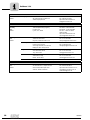
P.MC.. Industrial
Gear Unit Series
Edition 06/2007
11645814 / EN
Operating Instructions
SEW-EURODRIVE – Driving the world
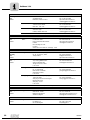
Contents
1
Important Notes................................................................................................. 5
1.1 Explanation of symbols ............................................................................. 7
1.2 Operating notes ........................................................................................ 7
2
Safety Notes ...................................................................................................... 8
2.1 Introduction ............................................................................................... 8
2.2 General information .................................................................................. 8
2.3 Symbols on the gear unit ........................................................................ 10
2.4 Transport................................................................................................. 11
2.5 Corrosion and surface protection............................................................ 13
3
Gear Unit Design ............................................................................................. 17
3.1 Combination of P.. planetary gear unit with MC.. primary gear unit........ 17
3.2 Design of the planetary gear unit ............................................................ 18
3.3 Design of the MC.P.. series primary gear unit ....................................... 20
3.4 Design of the MC.R.. series primary gear unit ........................................ 21
3.5 Unit designation, nameplates.................................................................. 22
3.6 Mounting positions .................................................................................. 24
3.7 Shaft position .......................................................................................... 25
3.8 Direction of rotation................................................................................. 25
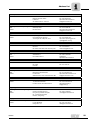
4
Installation / Assembly ................................................................................... 31
4.1 Required tools / aids ............................................................................... 31
4.2 Installation tolerances ............................................................................. 31
4.3 Prerequisites for assembly...................................................................... 31
4.4 Preliminary work ..................................................................................... 32
4.5 Notes on installing the gear unit.............................................................. 33
4.6 Flange mounting ..................................................................................... 34
4.7 Mounting torque arms for hollow shaft gear units ................................... 35
4.8 Assembly / disassembly of hollow shaft gear units and shrink discs ...... 39
4.9 Mounting a motor with motor adapter ..................................................... 42
5
Mechanical Installation Options .................................................................... 45
5.1 Important installation instructions............................................................ 45
5.2 Installing couplings.................................................................................. 48
5.3 FXM backstop ......................................................................................... 55
5.4 SHP shaft end pump............................................................................... 58
5.5 Oil heater ................................................................................................ 61
5.6 PT100 temperature sensor ..................................................................... 67
5.7 Fan.......................................................................................................... 68
5.8 Flow switch ............................................................................................. 69
5.9 Visual flow indicator ................................................................................ 72
5.10 Oil expansion tank and oil riser pipe ....................................................... 73
5.11 Connecting the oil / water cooling system............................................... 73
5.12 Connecting the oil / air cooling system ................................................... 73
5.13 Connecting the motor pump.................................................................... 73
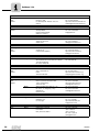
6
Startup.............................................................................................................. 74
6.1 Gear unit startup .................................................................................... 74
6.2 Startup of gear units with long-term protection ....................................... 75
6.3 Startup of gear units with backstop......................................................... 76
6.4 Shutting down the gear unit .................................................................... 76
7
Inspection and Maintenance .......................................................................... 77
7.1 Inspection and maintenance intervals..................................................... 78
7.2 Lubricant change intervals ...................................................................... 79
7.3 Checking the oil level .............................................................................. 80
7.4 Checking the oil consistency................................................................... 80
7.5 Changing the oil ...................................................................................... 81
7.6 Checking and cleaning the breather plug ............................................... 82
Operating Instructions – P.MC.. Industrial Gear Unit Series
3
Contents
4
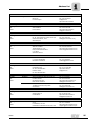
8
Malfunctions .................................................................................................... 83
8.1 Customer service .................................................................................... 83
8.2 Gear unit malfunctions ............................................................................ 84
9
Lubricants........................................................................................................ 85
9.1 Guidelines for lubricant selection ............................................................ 85
9.2 Lubricant table ........................................................................................ 86
9.3 Lubricant fill quantity ............................................................................... 88
9.4 Sealing grease ........................................................................................ 88
10
Index................................................................................................................. 89
Operating Instructions – P.MC.. Industrial Gear Unit Series
Important Notes
1
1
Important Notes
Introduction
Adhering to the operating instructions is a prerequisite for fault-free operation and the
fulfillment of any right to claim under warranty. Read the operating instructions before
you start working with the unit.
Make sure that the operating instructions are available to persons responsible for the
system and its operation, as well as to persons who work independently on the unit.
Also observe other technical documents, delivery contracts or other agreements.
General
information
P.MC.. industrial gear units are a combination of
1. P.. planetary gear units output stage
2. MC.R.. or MC.P.. primary gear unit
3. Motor, coupling, adapter and backstop, if required.
Designated use
The designated use refers to the procedure specified in the operating instructions.
The P.MC.. industrial gear units are units run by motors for industrial and commercial
systems. Gear unit utilizations other than those specified and areas of application other
than industrial and commercial systems can only be used after consultation with SEWEURODRIVE.
In compliance with the EC Machinery Directive 98/37/EC, the P.MC.. industrial gear
units are components for installation in machinery and systems. In the scope of the EC
directive, you must not take the machinery into operation in the designated fashion until
you have established that the end product complies with the Machinery Directive
98/37/EC.
Qualified personnel
P.MC.. series industrial gear units represent a potential hazard for persons and material.
Consequently, assembly, installation, startup and service work may only be performed
by trained personnel who are aware of the potential hazards.
The personnel must be appropriately qualified for the task in hand and must be familiar
with the
•
Assembly
•
Installation
•
Startup
•
Operation
•
Maintenance
•
Servicing
of the product.
The personnel must read the operating instructions, in particular the safety notes section, carefully and ensure that they understand and comply with them.
Operating Instructions – P.MC.. Industrial Gear Unit Series
5
Important Notes
1
Exclusion of liability
You must comply with the information contained in these operating instructions to ensure safe operation of the P.MC.. gear unit series and to achieve the specified product
characteristics and performance requirements.
SEW-EURODRIVE GmbH & Co KG assumes no liability for injury to persons or damage
to equipment or property resulting from non-observance of these operating instructions.
In such cases, any liability for defects is excluded.
Product names and trademarks
The brands and product names in these operating instructions are trademarks or registered trademarks of the titleholders.
Disposal
6
(Please follow the latest regulations):
•
Housing parts, gears, shafts and roller bearings of the gear units must be disposed
of as steel scrap. This also applies to gray-cast iron parts if there is no special collection.
•
Collect waste oil and dispose of it according to the regulations in force.
Operating Instructions – P.MC.. Industrial Gear Unit Series
Important Notes
Explanation of symbols
1.1
1
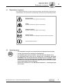
Explanation of symbols
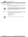
The operating instructions contain important information that deals with general and operational safety. This information is emphasized in particular with the following symbols.
Electrical hazard
Possible consequences: Severe or fatal injuries.
Hazard
Possible consequences: Severe or fatal injuries.
Hazardous situation
Possible consequences: Slight or minor injuries.
Harmful situation
Possible consequences: Damage to the drive and the environment.
Tips and useful information.
1.2
Operating notes
•
The nameplate of the gear unit contains the most important technical data.
•
The two gear units have a common oil compartment!
•
The industrial gear units of the P.MC.. series are delivered without oil fill.
•
The mounting position may only be changed after consultation with SEWEURODRIVE. The warranty will become void without prior consultation. When
changing to a vertical mounting position of the MC.. gear unit (M2, M4), oil compensator or oil riser pipe are required. Adjust the lubricant fill volume and position of the breather valve accordingly.
•
Observe the instructions in the "Mechanical installation" / "Installing the gear
unit" section.
Operating Instructions – P.MC.. Industrial Gear Unit Series
7
Safety Notes
Introduction
2
2
Safety Notes
2.1
Introduction
2.2
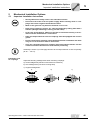
•
The following safety notes are concerned with the use of industrial gear units
of the P.MC.. series.
•
Please also take account of the supplementary safety notes in the individual
sections of these operating instructions.
General information
Burns hazard!
Touching the gear unit when it has not been cooled will result in burns. The gear unit
can have a surface temperature of more than 100 °C.
Never touch the gear unit during operation or in the cool down phase once the unit has
been switched off.
Never install damaged products or take them into operation.
Submit a complaint to the shipping company immediately in the event of damage.
During or after operation, industrial gear units and motors have:
•
Live parts
•
Moving parts
•
Hot surfaces (may be the case)
Only qualified personnel may carry out the following work:
•
Installation / assembly
•
Connection
•
Startup
•
Maintenance
•
Servicing
The following information and documents must be observed during these processes:
•
Relevant operating instructions and wiring diagrams
•
Warning and safety signs on the gear unit
•
System-specific regulations and requirements
•
National/regional regulations governing safety and the prevention of accidents
Serious injuries and property damage may result from:
8
•
Improper use
•
Incorrect installation or operation
•
Unauthorized removal of necessary protection cover or housing
Operating Instructions – P.MC.. Industrial Gear Unit Series
Safety Notes
General information
2
Startup / operation
•
Check that the direction of rotation is correct in decoupled condition. Pay attention to unusual grinding noises as the shaft rotates.
•
Secure the keys without output elements for the test run.
•
Do not deactivate monitoring and protection equipment during the test run.
•
When in doubt, switch off the main motor whenever changes occur in relation to normal operation (such as increased temperatures, noise, oscillation). Determine the
cause of the fault and consult SEW-EURODRIVE.
•
Work carefully and keep safety in mind.
•
Work on the gear unit and additional equipment only when the machine is not in use.
Prevent the drive unit from being accidentally switched on by locking the keyswitch
or removing the fuses from the power supply. Attach an information sign near the ON
switch to warn that the gear unit is being worked on.
•
Observe the notes attached to the gear unit, such as the nameplate and direction arrow. They must be free of paint and dirt. Replace missing signs.
•
When installing the gear unit in devices or systems, the manufacturers of the device
or system are obliged to include the regulations, notes, and descriptions from these
operating instructions in their own operating instructions.
•
Purchase spare parts from SEW-EURODRIVE.
Inspection / maintenance
Refer to the instructions in Sec. "Inspection and Maintenance."
Operational environment
•
The gear unit is not suited for operation in potentially explosive atmospheres!
•
Follow the specifications regarding contract-specific ambient temperature ratings and ambient conditions. Modifications require prior approval by SEWEURODRIVE.
Operating Instructions – P.MC.. Industrial Gear Unit Series
9
Safety Notes
Symbols on the gear unit
2
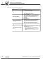
2.3
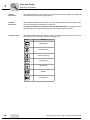
Symbols on the gear unit
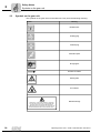
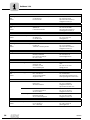
The symbols on the gear unit must be observed. They have the following meaning:
Symbol
Meaning
Breather valve
Oil filling plug
Oil drain plug
Lubrication point
MIN
Oil sight glass
Direction of rotation
Delivery state
DELIVERED
WITHOUT OIL
Hot surfaces
Extended storage
GEAR UNIT IS VPI ANTI-RUST TREATED. COVER AND
PLUG OF GEAR UNIT MUST NOT TO BE OPENED AND
GEAR UNIT MUST NOT ROTATED BEFORE STARTUP. BEFORE START-UP THE PROTECTIVE PLUG MUST BE
REMOVED AND REPLACED BY ENCLOSED AIR VALVE.
10
Operating Instructions – P.MC.. Industrial Gear Unit Series
Safety Notes
Transport
2.4
2
Transport
General information
•
Inspect the shipment for any damage in transit as soon as you receive the delivery. Inform the shipping company immediately. It may be necessary to preclude startup.
•
Stay away from beneath the gear unit during transport.
•
Secure the danger zone.
•
During transport, use only hoists and load-bearing equipment with sufficient
load-bearing capacity.
•
The weight of the gear unit is indicated on the nameplate or the dimension
sheet. Observe the loads and regulations specified on the nameplate.
•
The gear unit must be transported in a manner that prevents injuries and damage to the gear unit. For example, impacts against exposed shaft ends can
damage the gear unit.
•
Do not use the eyebolts on motors, auxiliary gear units or primary gear units
during transport of the assembled drive unit (see next page).
•
Use suitable, sufficiently rated handling equipment if necessary. Before startup, remove securing devices used for transport.
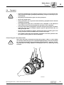
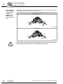
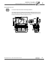
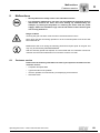
Transporting gear units without motor
Gear units may only be transported using lifting straps, cables or chains. Make
sure that the load of the gear unit is distributed appropriately. The main load must
be carried by the transport eye [1] and lifting strap [2] of the P.. gear unit. The lifting chain [3[ at the lifting eyebolts of the MC gear unit is for balancing during
transport.
[3]
[3]
[2]
[1]
61082AXX
Operating Instructions – P.MC.. Industrial Gear Unit Series
11
2
Safety Notes
Transport
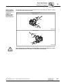
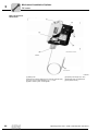
Transporting gear units with motor adapter
Gear units may only be transported using lifting straps, cables or chains. Make
sure that the load of the gear unit and the motor is distributed appropriately. The
main load must be carried by the transport eye [1] and lifting strap [2] of the P..
gear unit. The lifting strap [3] at the motor adapter and the lifting chain [4] at the
lifting eyebolts of the MC gear unit is for balancing during transport.
[4]
[4]
[3]
[1]
[2]
61084AXX
12
Operating Instructions – P.MC.. Industrial Gear Unit Series
Safety Notes
Corrosion and surface protection
2.5
2
Corrosion and surface protection
The information in this section apply only to P.MC.. series industrial gear units assembled in Europe. Other paint systems might be used in other regions. Please consult the
SEW-EURODRIVE assembly plant for P.MC.. industrial gear units at your location.
Introduction
The corrosion and surface protection of gear units comprises the following three basic
features:
1. Painting system
•
•
Standard painting system K7 E160/2
High-resistant painting system K7 E260/3 as option
2. Gear unit corrosion protection with
•
•
interior protection and
exterior protection
3. Gear unit packing
•
•
•
Standard painting system K7
E160/2
Standard packing (pallet)
Wooden box
Seaworthy packaging
Painting according to TEKNOS EPOXY SYSTEM K7 based on the high-solid epoxy
paint TEKNOPLAST HS 150.
Two-layer system K7 E 160/2
Thickness
•
Epoxy primer
60 µm
•
Teknoplast HS 150
100 µm
Total thickness
160 µm
Color shade: RAL 7031, blue gray
Protective covers
Powder coating, epoxy-based coat paint (EP) is used for guards and shields.
Layer thickness: 65 µm
Color shade: TM 1310 PK, warning in yellow color
High-resistant
painting system
K7 E 260/3
Painting according to TEKNOS EPOXY SYSTEM K7 based on the high-solid epoxy
paint TEKNOPLAST HS 150.
Three-layer system, K7 E 260/3
•
Epoxy primer
•
Teknoplast HS 150
Total thickness
Optional color
shade
Thickness
60 µm
2x100 µm
260 µm
Other color shades are available on request.
Operating Instructions – P.MC.. Industrial Gear Unit Series
13
Safety Notes
Corrosion and surface protection
2
Using the
painting system
Environmental
pollution
None
Low
Unheated buildings where condensation can
build up.
Typical environmental conditions
High
Production halls
with high humidity levels and low
air contamination.
Atmospheres with
low pollution.
Mostly rural areas.
City and industrial
atmospheres,
moderate contamination with sulphur dioxide.
Coastal areas with
low salt load.
Very high
Industrial areas
and coastal areas
with moderate salt
load.
Chemical plants
Buildings or areas
with almost permanent condensation and high
levels of contamination.
Industrial areas
with very high levels of moisture
and aggressive
atmospheres.
Installation
Indoors
Indoors
Indoors or outdoors
Indoors or outdoors
Indoors or outdoors
Relative humidity
< 90 %
Up to 95 %
Up to 100 %
Up to 100 %
Up to 100 %
Recommended
painting system
Standard painting
system
K7 E160/2
Standard painting
system
K7 E160/2
Standard painting
system
K7 E160/2
High resistant painting system
K7 E260/3
Consult
SEW-EURODRIVE
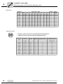
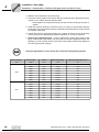
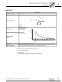
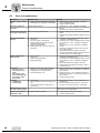
Industrial gear units of the P.MC.. series are delivered without oil fill. Different protection
systems are required depending on storage period and ambient conditions:
Storage and
transport
conditions
Storage
period: Up to
… months
14
Medium
Storage conditions
Gear unit corrosion protection
Transport conditions
Gear unit packaging
OUTDOORS, roofed
INDOORS, heated
(0…+20°C)
Storage OUTDOORS close to
the sea, roofed
Storage close
to the sea
INDOORS
Land
transport
Sea
transport
6
Standard
protection
Standard
protection
Consult
SEW-EURODRIVE
Long-term
protection
Standard
packaging
Seaworthy
packaging
12
Consult
SEW-EURODRIVE
Standard
protection
Consult
SEW-EURODRIVE
Long-term
protection
Standard
packaging
Seaworthy
packaging
24
Long-term
protection
Consult
SEW-EURODRIVE
Consult
SEW-EURODRIVE
Long-term
protection
Standard
packaging
Seaworthy
packaging
36
Consult
SEW-EURODRIVE
Long-term
protection
Consult
SEW-EURODRIVE
Long-term
protection
Standard
packaging
Seaworthy
packaging
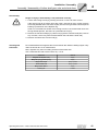
Standard protection / interior
•
Gear units undergo a test run with protection oil. The protection oil is drained by
SEW-EURODRIVE before dispatch. The remaining layer of protection oil on the inner parts serves as basic protection.
Standard protection / exterior
•
Oil seals and seal surfaces are protected by suitable bearing grease.
•
Unpainted surfaces (including spare parts) are covered with a protective coating. Remove the coating using a solvent before mounting other equipment onto the surface.
•
Small spare parts and loose pieces, such as screws, nuts, etc., are supplied in corrosion protection plastic bags (VCI corrosion protection bag).
•
Threaded holes and blind holes are covered by plastic plugs.
•
The breather plug (position → see order documents) is already installed at the
factory.
Operating Instructions – P.MC.. Industrial Gear Unit Series
Safety Notes
Corrosion and surface protection
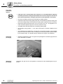
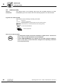
Standard protection / packaging
2
Standard packaging is used: The gear unit is delivered on a pallet without cover.
58048AXX
Long-term protection / interior
Internal gear unit protection in addition to the "standard protection":
•
A VPI solvent is sprayed through the oil filling hole.
•
Never open the gear unit near open flames, sparks and hot objects because the
solvent vapors might be ignited.
•
Take preventive measures to protect people from the solvent vapors. Make
sure that open flames are avoided when the solvent is applied and when it
evaporates.
•
The output shaft must be rotated by at least one turn so that the position of the
roller elements in the bearings of LSS and HSS changes. This procedure has
to be repeated every 6 months until startup.
•
The interior long-term protection with the VPI solvent has to be repeated every
24 / 36 months until startup (according to the table "Storage and transport conditions").
Operating Instructions – P.MC.. Industrial Gear Unit Series
15
Safety Notes
Corrosion and surface protection
2
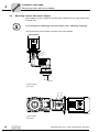
Long-term
protection /
exterior
Seaworthy
packaging
•
If the gear unit is stored longer than 6 months, it is recommended to regularly
check the protective coating of unpainted areas as well as the paint coat. Areas
with removed protection coating or paint have to be repainted, if necessary.
•
Oil seals and sealing surfaces are protected by suitable grease.
•
Unpainted surfaces (including spare parts) are covered with a protective coating. Remove the coating using a solvent before mounting other equipment onto the surface.
•
Small spare parts and loose pieces, such as screws, nuts, etc., are supplied in corrosion protection plastic bags (VCI corrosion protection bag).
•
Threaded holes and blind holes are covered by plastic plugs.
•
The breather plug (position → see order documents) is already installed at the
factory.
•
The breather plug is replaced by a screw plug. You find the position of the breather
plug in the order documents. Prior to startup, the screw plug must be replaced again
by the breather plug. The breather plug is attached to the gear unit separately.
•
Seaworthy packaging is used: The gear unit is packaged in a seaworthy plywood box
and is delivered on a pallet.
57585AXX
Alternative
packaging
16
Optionally, the gear unit can be supplied in a wooden box with standard gear unit protection.
Operating Instructions – P.MC.. Industrial Gear Unit Series
Gear Unit Design
Combination of P.. planetary gear unit with MC.. primary gear unit
3
Gear Unit Design
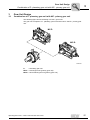
3.1
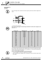
Combination of P.. planetary gear unit with MC.. primary gear unit
3
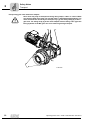
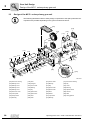
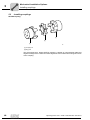
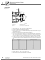
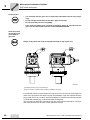
The following figure shows the design of P.MC.. gear units .
The gear unit comprises a P.. planetary gear unit and an MC.P../MC.R.. primary gear
unit.
MC.P..
MC.R..
P..
58063AXX
P..
= Planetary gear unit
MC.P.. = Helical gear unit (primary gear unit)
MC.R.. = Bevel-helical gear unit (primary gear unit)
Operating Instructions – P.MC.. Industrial Gear Unit Series
17
Gear Unit Design
Design of the planetary gear unit
3
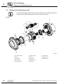
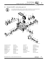
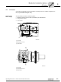
3.2
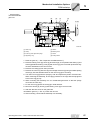
Design of the planetary gear unit
The following illustrations allow to easily assign components to the spare parts lists. Discrepancies are possible depending on the gear unit size and version.
P1..MC..
[5]
[4]
[3]
[2]
[1]
[1]
[13]
[6]
[8]
[7]
[9]
[11]
[10]
[12]
58049AXX
[1] Planetary bearing
18
[6] Gear coupling
[11] Bearing race
[2] Circlip
[7] Bearing
[12] Flange cover
[3] Planet bolt
[8] Sun pinion
[13] Sealing ring
[4] Planet wheel
[9] Holding screw
[5] Housing gear rim
[10] Bearing
Operating Instructions – P.MC.. Industrial Gear Unit Series
Gear Unit Design
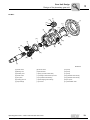
Design of the planetary gear unit
3
P2..MC..
[17]
[4]
[7]
[12]
[14]
[3]
[10]
[6]
[2]
[15]
[19]
[8]
[11]
[16]
[1]
[20]
[5]
[18]
[13]
[9]
[21]
58229AXX
[1] Planet carrier
[8] Planet carrier
[15] Circlip
[2] Bearing race
[9] Planet wheel
[16] Circlip
[3] Planetary axle
[10] Key (not with hollow shaft)
[17] Circlip
[4] Planet wheel
[11] Hexagon socket head cap screw
[18] Cylindrical roller bearing
[5] Sun pinion
[12] Cylindrical roller bearing
[19] Cylindrical roller bearing
[6] Housing gear rim
[13] Self-aligning roller bearing
[20] Sun pinion
[7] Output flange
[14] Oil seal
[21] Intermediate shaft
Operating Instructions – P.MC.. Industrial Gear Unit Series
19
Gear Unit Design
Design of the MC.P.. series primary gear unit
3
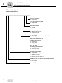
3.3
Design of the MC.P.. series primary gear unit
The following illustrations allow to easily assign components to the spare parts lists. Discrepancies are possible depending on the gear unit size and version.
[070]
[010]
[199]
[195]
[110]
[299]
[725]
[131]
[210]
[395]
[310]
[301]
[399]
[231]
[242]
[040]
[295]
[210]
[201]
[495]
[340]
[480]
[438]
[310]
[395]
[434]
[410]
[430]
[411]
[401]
[025]
[342]
[100]
[195]
[243]
[331]
[725]
[110]
[015]
[295]
[443]
[495 ]
MC2P..
[001]
[075]
[342]
60331AXX
[001] Gear unit housing
20
[195] Shim
[301] Pinion shaft
[411] Anti-friction bearing
[010] Bearing cover
[199] End gear
[310] Bearing
[430] Key
[015] Bearing cover
[201] Pinion shaft
[331] Key
[434] Cover
[025] Bearing cover
[210] Bearing
[340] Spacer tube
[438] Bushing
[040] Bearing cover
[231] Key
[342] Spacer tube
[443] Spacer sleeve
[070] Gear unit cover
[242] Spacer tube
[395] Shim
[480] Oil seal
[075] Cover plate
[243] Spacer tube
[399] Wheel
[495] Shim
[100] Output shaft
[295] Shim
[401] Input shaft
[725] Lifting eyebolt
[110] Bearing
[299] Gear
[410] Bearing
Operating Instructions – P.MC.. Industrial Gear Unit Series
Gear Unit Design
Design of the MC.R.. series primary gear unit
3.4
3
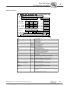
Design of the MC.R.. series primary gear unit
The following illustration allows to easily assign components to the spare parts lists.
Discrepancies are possible depending on the gear unit size and version.
[070]
[010]
[199]
[195]
[110]
[131]
[100]
[110]
[015]
[243]
[295]
[299]
[195]
[725]
[210]
[331]
[342] [025]
[725]
[231]
[242]
[295]
[210]
[340]
[025]
[399]
[201]
[301]
[341]
[310]
[430]
[410]
[495]
[001]
[395]
[395]
[401]
[310]
[422]
[080]
[342]
[423]
[480]
[040]
[411]
[470]
[436]
58516AXX
[001] Gear unit housing
[195] Shim
[310] Bearing
[411] Bearing
[010] Bearing cover
[199] End gear
[331] Key
[422] Bearing bushing
[015] Bearing cover
[201] Pinion shaft
[340] Spacer tube
[423] Bearing bushing
[025] Bearing cover
[210] Bearing
[341] Spacer tube
[430] Key
[040] Cover
[231] Key
[342] Spacer tube
[436] Bushing
[070] Gear unit cover
[242] Spacer tube
[395] Shim
[470] Clamping nut
[080] Bearing cover
[243] Spacer tube
[399] Bevel gear
[480] Oil seal
[100] Output shaft
[295] Shim
[401] Bevel pinion shaft
[495] Shim
[110] Bearing
[299] Gear
[410] Bearing
[725] Lifting eyebolt
[131] Key
[301] Pinion shaft
Operating Instructions – P.MC.. Industrial Gear Unit Series
21
Gear Unit Design
Unit designation, nameplates
3
3.5
Unit designation, nameplates
Sample unit designation
P
1
H
F
031
/...
MC
2
R
L
S
T
05
Size: 02 ... 09
Gear unit mounting:
T = Torque arm
Low speed shaft type (LSS):
S = Solid shaft
Mounting position:
L = horizontal
V = vertical
E = upright
Gear unit design:
R = Bevel-helical gear unit
P = Helical gear unit
Number of gear unit stages of the primary gear unit
2 = two stages
3 = three stages
MC.. series primary gear unit
Installing the gear unit
T = Torque arm
S = Swing base
Size: 001...081
Planetary gear unit mounting
... = Foot-mounted
F = Flange-mounted
Planetary gear unit type
S = Solid shaft
R = Solid shaft with key
L = Splined solid shaft
V = Splined hollow shaft
H = Hollow shaft with shrink disc
Number of gear unit stages of the planetary gear unit
1 = 1-stage
2 = two stages
Planetary gear units
22
Operating Instructions – P.MC.. Industrial Gear Unit Series
Gear Unit Design
Unit designation, nameplates
3
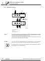
Example nameplate
SEW-EURODRIVE
Bruchsal / Germany
Type P061
Nr. 1 01.1119651601.0001.05
Nr. 2
W10527
1:
39.23
norm.
min.
max.
i
PK1 [kW]
12.7
2.3
15.8
FS
MK2 [kNm]
75.4
75.4
75.4
FR1
[kN] 0
n1
[1/min]
62
11.7
78.5
FR2
[kN] 0
n2
[1/min]
1.6
0.3
2.0
FA1
[kN] 0
Operation instructions have to be observed! FA2
[kN] 0
Made by
SEW
2.5
1770
Mass [kg]
Qty of greasing points 0 Fans 0
Synthetic ISO VG 460 EPPAO - 25 ltr.
Lubricant
Year 2007
FSA GmbH EUCode0588 // IM: M1-F1 // Tu = 0 ... 40 °C
61079AXX
Type
Unit designation
No. 1
Serial number 1
No. 2
Serial number 2
[kW]
PK1
Gear unit force
MK2
[kNm]
Gear unit output torque
n1
[1/min]
Input speed (HSS)
n2
[1/min]
Output speed (LSS)
norm.
Standard operating point
min.
Operating point at minimum speed
max
Operating point at maximum speed
i
Exact gear unit reduction ratio
FS
Service factor
FR1
[kN]
Actual overhung load acting on the drive shaft
FR2
[kN]
Actual overhung load acting on the output shaft
FA1
[kN]
Actual axial load acting on the drive shaft
FA2
[kN]
Actual axial load acting on the output shaft
Mass
[kg]
Weight of the gear unit
Number of greasing points
Number of points that require regreasing
Fans
Number of installed fans
Lubricant
Oil grade and viscosity class / oil volume
Year
Year of construction
IM
Mounting position: Housing orientation and mounting surface
variants
Tu
Permitted ambient temperature
Operating Instructions – P.MC.. Industrial Gear Unit Series
23
Gear Unit Design
Mounting positions
3
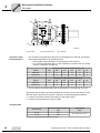
3.6
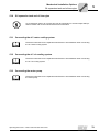
Mounting positions
Mounting position designations
SEW-EURODRIVE differentiates between mounting positions M1, M2 and M4. The following figure shows the spatial orientation of the gear unit.
The mounting positions apply to planetary gear units with solid shafts and hollows
shafts.
For a different position of the primary gear unit, see order documents.
P..MC.P
M2
M2
M1
M1
M4
M4
M2
P..MC.R
M2
M1
M1
M4
M4
57886AXX
24
Operating Instructions – P.MC.. Industrial Gear Unit Series
Gear Unit Design
Shaft position
3.7
3
Shaft position
The following figure shows the shaft position (0, 1, 2, 3, 4).
2
4
0
0
3
3.8
1
58065AA
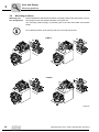
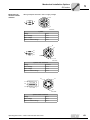
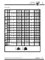
Direction of rotation
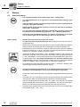
Shaft positions
and directions of
rotation P.MC2P..
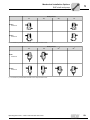
The following figures show shaft positions and corresponding directions of rotation for
P.MC2P.. series industrial gear units.
2-stage primary gear unit
Shaft position 1-4
CCW
CW
CW
CCW
57969AXX
Shaft position 2-3
CCW
CW
CW
CCW
57991AXX
Operating Instructions – P.MC.. Industrial Gear Unit Series
25
3
Gear Unit Design
Direction of rotation
Shaft positions
and corresponding directions of
rotation of
P.MC3P..
The following figures show shaft positions and corresponding directions of rotation for
P.MC3P.. series industrial gear units.
3-stage primary gear unit
Shaft position 1-4
CCW
CW
CW
CCW
57994AXX
Shaft position 2-3
CCW
CW
CW
CCW
57997AXX
Shaft positions
and corresponding directions of
rotation of
P.MC.R.. without
backstop
The following figures show shaft positions and corresponding directions of rotation for
two and three stage P.MC.R.. series industrial gear units without backstop.
Two and three stages primary gear units
Shaft position 0-4
CW
CCW
CW
CCW
58005AXX
Shaft position 0-4
CCW
CW
CCW
CW
58006AXX
26
Operating Instructions – P.MC.. Industrial Gear Unit Series
Gear Unit Design
Direction of rotation
Shaft positions
and corresponding directions of
rotation of
P.MC2RS.. /
P.MC2RH.. keyway with backstop
3
The following figures show shaft positions and directions of rotation for two-stage gear
units with backstop of the types P.MC.RS..and P.MC.RH.. with keyway.
2-stage primary gear unit
Shaft position 0-4
CW
CCW
CW
CCW
58009AXX
Shaft position 0-3
CCW
CW
CCW
CW
58011AXX
Only one direction of rotation is possible, which has to be specified in the order.
The permitted direction of rotation is indicated on the housing.
Operating Instructions – P.MC.. Industrial Gear Unit Series
27
3
Gear Unit Design
Direction of rotation
Shaft positions
and corresponding direction of
rotation for
P.MC3R.. with
backstop on
driven machine
end
The following figures show the shaft positions and direction of rotation dependencies for
3-stage gear units with backstop of type P.MC.3R..
3-stage primary gear unit
Shaft position 0-4
CW
CCW
CW
CCW
58012AXX
Shaft position 0-3
CW
CCW
CW
CCW
55956AXX
Only one direction of rotation is possible, which has to be specified in the order.
The permitted direction of rotation is indicated on the housing.
28
Operating Instructions – P.MC.. Industrial Gear Unit Series
Gear Unit Design
Direction of rotation
Shaft positions
and corresponding directions of
rotation of
P.MC3R.. Backstop opposite
driven machine
3
The following figures show the shaft positions and corresponding directions of rotation
for gear units with backstop P.MC3R.
3-stage primary gear unit
Shaft position 0-4
CW
CCW
CW
CCW
58014AXX
Shaft position 0-3
CCW
CW
CCW
CW
58015AXX
Only one direction of rotation is possible, which has to be specified in the order.
The permitted direction of rotation is indicated on the housing.
Operating Instructions – P.MC.. Industrial Gear Unit Series
29
Gear Unit Design
Direction of rotation
3
Splash
lubrication
With splash lubrication, the oil level is low. With this lubrication method, oil is splashed
onto the bearings and gearing components.
Oil bath
lubrication
With oil bath lubrication, the oil level is so high that the bearings and gearing components are completely immersed in the lubricant.
Oil expansion tanks can always be used with bath lubrication. Oil expansion tanks
allow the lubricant to expand when the gear unit heats up during operation.
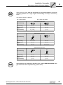
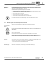
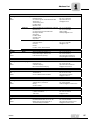
Symbols used
The following table shows the symbols used in the order documents. Refer to the order
documents for the mounting positions of the gear units.
Symbol
Meaning
Breather plug
Air outlet screw
Inspection opening
Oil filling plug
Oil drain plug
Dipstick
Oil sight glass
30
Operating Instructions – P.MC.. Industrial Gear Unit Series
Installation / Assembly
Required tools / aids
4
Installation / Assembly
4.1
Required tools / aids
4
Not included in the scope of delivery:
4.2
•
Set of wrenches
•
Torque wrench (for shrink discs)
•
Motor mount on motor adapter
•
Mounting device
•
Compensation elements (shims, spacing rings)
•
Fixing devices for input and output elements
•
Mount the parts according to the gear unit illustrations shown in the "Gear unit foundation" section.
Installation tolerances
shaft end
Primary gear unit MC..
Diameter tolerance
> 50 mm -> ISO m6
Center hole in accordance with DIN 332, shape
D..
d, d1 > 85.0.130 mm -> M24
> 130..180 mm -> M30
> 180 mm
-> -
P.. planetary gear units
Shaft end ISO m6
4.3
Flanges
Centering shoulder tolerance -> ISO m8
Centering shoulder ISO f8
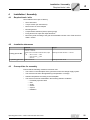
Prerequisites for assembly
Ensure that the following conditions have been met:
•
The entries on the nameplate of the gearmotor match the voltage supply system.
•
The drive has not been damaged during transportation or storage.
•
Ambient temperature according to the nameplate.
•
The drive must not be assembled in the following ambient conditions:
–
–
–
–
–
–
Potentially explosive area
Oils
Acids
Gases
Vapors
Radiation
Operating Instructions – P.MC.. Industrial Gear Unit Series
31
Installation / Assembly
Preliminary work
4
4.4
Preliminary work
Clean the shaft
Ensure sufficient ventilation when using solvents. There is a risk of explosion. No
open flames.
Risk of material damage.
Do not let the solvent come into contact with the sealing lips of the oil seals.
Long-termstorage
•
You must clean the output shafts and flange surfaces thoroughly to ensure they are
free of anti-corrosion agents, contamination or similar. Use a commercially available
solvent.
•
Protect all oil seals against direct contact with abrasive substances (such as sand,
dust, shavings).
Please note: The service life of the bearing lubricant in the bearing is reduced if the unit
is stored for ≥ 1 year.
P.MC.. gear units designed for "extended storage" usually have a higher oil level (CLP
PG). Adjust the oil level before startup (see Sec. "Inspection / Maintenance").
Oil check
Fill the P.MC.. gear unit with the oil grade and quantity specified on the nameplate
(see Sec. 'Startup' and 'Inspection and Maintenance'):
•
Fill to volume suitable for the mounting position (see nameplate)
•
Check oil level through oil sight glass or with oil dipstick
→ Sec. "Inspection and Maintenance" and "Design and Operating Notes".
32
Operating Instructions – P.MC.. Industrial Gear Unit Series
Installation / Assembly
Notes on installing the gear unit
4.5
4
Notes on installing the gear unit
•
You must strictly observe the safety instructions in the previous sections.
•
The most important technical data is indicated on the nameplate. Additional
data relevant for operation is available in drawings, order confirmation or any
order-specific documentation.
•
The gear unit must be installed with great care by qualified personnel. Damage
caused by improper handling leads to exclusion of liability.
•
Install / mount the gear unit only in the specified mounting position on a level,
vibration-damping, and torsionally rigid support structure. Do not tighten
housing legs and mounting flanges against each other.
•
Work on the gear unit only when the machine is not in use. Prevent the drive
unit from starting up unintentionally (for example, by locking the keyswitch or
removing the fuses from the power supply). Attach an information sign near
the ON switch to warn that the gear unit is being worked on.
•
The oil level and drain plugs as well as the breather valves must be freely accessible.
•
Use plastic inserts (2 to 3 mm thick) if there is a risk of electrochemical corrosion between the gear unit and the driven machine (connection between different metals such as cast iron and high-grade steel). Also fit the plugs with plastic washers. Ground the housing additionally - use the grounding screws on
the motor.
•
Before startup, check whether the oil fill corresponds to the specified mounting position (→ information on the nameplate).
•
The mounting position may only be changed after consultation with SEWEURODRIVE. Warranty will become void without prior consultation.
•
Only authorized personnel may assemble gear head units with motors and
adapters. Please contact SEW-EURODRIVE.
•
Do not weld anywhere on the drive. Do not use the drive as a ground point for
welding work. Welding may destroy gearing parts and bearings.
•
Protect rotating drive parts, such as couplings, gears, or belt drives, using
suitable devices that protect from contact.
•
Units installed outdoors must be protected from the sun. Suitable protective
devices are required, such as covers or roofs. When using these, avoid heat
accumulation. The operator must ensure that foreign objects do not impair the
function of the gear unit (e.g. by falling objects, or coverings).
•
Gear units are supplied with suitable coating for use in damp areas or in the
open air. Any damage to the coating (e.g. on the breather valve) must be repaired.
•
For the standard mounting positions, the breather valve on the gear unit is
mounted at the factory and activated if the gear unit is supplied without oil fill.
Check the functionality of the breather valve and that it is seated correctly.
•
Only mount the couplings using a mounting device.
Operating Instructions – P.MC.. Industrial Gear Unit Series
33
Installation / Assembly
Flange mounting
4
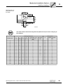
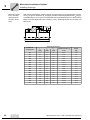
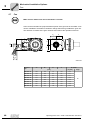
4.6
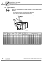
Flange mounting
During gear unit mounting on the torque arm and / or machine frame, note the
following:
•
Only use class 8.8 screws in accordance with the table below.
•
Tighten the screws with the specified tightening torque.
•
In addition, apply Loctite 640 to the screw contact surface [1].
05824AXX
Gear unit
type P
Screws
Thread
Number
Strength
classes
DIN
34
Tightening
torque
Dimensions in [mm]
[Nm] ± 20 %
∅S
H
L
L1
∅A
∅B
∅C
P..001MC..
912/931
M20
20
8.8
310
22
36
70
34
410
370
330 f8
P..011.MC..
912/931
M20
20
8.8
310
22
38
70
32
450
410
370 f8
P..021MC..
912/931
M20
24
8.8
310
22
44
80
36
500
460
410 f8
P..031MC..
912/931
M24
20
8.8
540
26
46
80
34
560
510
460 f8
P..041MC..
912/931
M30
20
8.8
1100
33
60
110
50
620
560
480 f8
P..051MC..
912/931
M30
24
8.8
1100
33
60
110
50
650
590
530 f8
P..061MC..
912/931
M36
24
8.8
1830
39
70
130
60
760
690
610 f8
P..071MC..
912/931
M36
24
8.8
1830
39
80
140
60
840
770
690 f8
P..081MC..
912/931
M42
24
8.8
3200
45
80
150
70
920
840
750 f8
Operating Instructions – P.MC.. Industrial Gear Unit Series
Installation / Assembly
Mounting torque arms for hollow shaft gear units
4.7
4
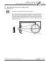
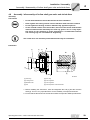
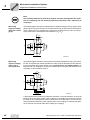
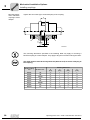
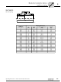
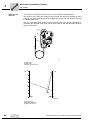
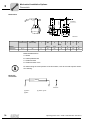
Mounting torque arms for hollow shaft gear units
Single-sided torque arm
Do not place torque arms under strain during installation.
The reactive force due to the gear unit torque is absorbed via the torque arm with lever
arm A. The illustration shows an example for absorption in a welded construction with
design dimensions. Two supporting plates are welded with the suggested dimensions
on the machine design. Once the gear unit has been mounted, a connecting cover plate
is welded onto the two supporting plates. The force of the gear unit torque acts on the
support, divided by the length of the lever arm A. The reaction force also acts on the gear
unit and machine shafts.
T
A
X
D5
S
B
D1
D2
O
C
51056AXX
Operating Instructions – P.MC.. Industrial Gear Unit Series
35
Installation / Assembly
Mounting torque arms for hollow shaft gear units
4
Dimensions
Gear unit
type
Dimensions in [mm]
A
B
C
D1
D2
D5
Number
O
S
T
Weight
X
[Kg]
P001
650
60
50
335
370
410
25
22
880
16
31
P011
700
70
60
375
410
450
30
22
955
20
36
P021
750
90
70
415
460
500
35
22
1035
24
58
P031
800
110
90
465
510
560
35
26
1125
20
70
P041
900
150
120
485
560
620
40
33
1270
20
117
P051
1000
160
130
535
590
650
40
33
1390
24
147
P061
1200
180
150
615
690
760
50
39
1655
24
183
P071
1500
230
200
695
770
840
60
39
2020
24
315
P081
1600
230
200
755
840
920
70
45
2160
24
360
Tightening torques
•
Only use class 8.8 screws in accordance with the table below.
•
Tighten the screws with the specified tightening torque.
Gear unit
type
Screws
Thread
Number
Strength classes
[Nm] ± 20 %
DIN
36
Tightening torque
P001
912/931
M20
20
8.8
310
P011
912/931
M20
20
8.8
310
P021
912/931
M20
24
8.8
310
P031
912/931
M24
20
8.8
540
P041
912/931
M30
20
8.8
1100
P051
912/931
M30
24
8.8
1100
P061
912/931
M36
24
8.8
1830
P071
912/931
M36
24
8.8
1830
P081
912/931
M42
24
8.8
3200
Operating Instructions – P.MC.. Industrial Gear Unit Series
Installation / Assembly
Mounting torque arms for hollow shaft gear units
4
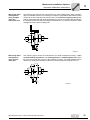
Double-sided torque arms
Do not place torque arms under strain during installation.
The reaction torque from the gear unit output torque is absorbed via the lever arms A.
The resulting reactive force is absorbed in the foundation. No reaction forces act on the
gear unit and machine bearings. The torque arm must be screwed onto a structure or
foundation provided by the customer using the foot screws.
L
O
D5
A
D3
L
X
S
D2
D1
J
D4
H
K
M
N
ØD6
S
F
E
E
T
C
C
B
V
60384AXX
Operating Instructions – P.MC.. Industrial Gear Unit Series
37
Installation / Assembly
Mounting torque arms for hollow shaft gear units
4
Dimensions
Dimensions in [mm]
Gear unit
type
A
B
C
D1
D2
D3
D4
D5
D6
E
F
H
P061
500
500
190
610
690
770
90
810
200
370
110
640
P071
600
500
190
690
770
850
90
890
200
470
110
640
P081
700
520
200
750
840
930
100
970
220
555
120
710
Gear unit
type
J
K
L
M
N
O
S
T
V
P061
1045
460
595
240
70
60
39
1140
560
24
780
P071
1085
460
695
240
70
60
39
1340
560
24
895
P081
1195
520
810
260
80
70
45
1560
600
24
1292
Dimensions in [mm]
Number
Weight
X
[Kg]
Tightening torques
Only use class 8.8 screws in accordance with the table below.
•
Tighten the screws with the specified tightening torque.
Thread
Number
Strength class
Tightening torque [Nm] ± 20 %
P061
912/931
M36
8
8.8
1830
P071
912/931
M36
8
8.8
1800
P081
912/931
M42
8
8.8
3200
Gear unit type
38
•
DIN screws
Operating Instructions – P.MC.. Industrial Gear Unit Series
Installation / Assembly
Assembly / disassembly of hollow shaft gear units and shrink discs
4.8
4
Assembly / disassembly of hollow shaft gear units and shrink discs
Assembly
instructions
•
Do not disassemble the shrink disc before the first installation.
•
Never tighten the locking screws until the machine shaft has been installed.
•
Do not tighten the locking screws in diametrically opposite sequence.
•
On the outside surface of the shrink disc, the bore of the hollow shaft and the
machine shaft must be absolutely free from any grease. This is a very important factor for the reliability of torque transmission. Contaminated solvents
and cleaning rags are not suitable for degreasing.
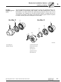
The shrink discs are delivered preassembled and ready for installation.
Installation
A
[7]
[2]
[1]
A
[6]
[3]
[4]
[5]
]8[
58199AXX
[1] Outer ring
[5] Inner ring
[2] Locking screw
[6] Free of grease
[3] Machine shaft
[7] Free of grease
[4] Hub
[8] Correct position of the shrink disc
1. Before installing the shrink disc, clean and degrease the hub [4] and the machine
shaft [3]. This is a very important factor for the reliability of torque transmission.
2. Ensure that the dimensions of the machine shafts correspond to SEW specifications.
Operating Instructions – P.MC.. Industrial Gear Unit Series
39
Installation / Assembly
Assembly / disassembly of hollow shaft gear units and shrink discs
4
3. Slide the loose shrink disc onto the hub [4].
4. Check the correct position of the shrink disc [8]. The shrink disc is positioned correctly when it is in contact with the shaft shoulder.
– Never tighten the locking screws [2] until the machine shaft [3] has been installed.
5. Install the machine shaft [3] or slide the hub [4] to a stop on the machine shaft [3].
Perform the mounting sequence slowly to allow the compressed air to escape around
the outside of the shaft.
6. Tighten the locking screws [2] manually first. Tighten all locking screws by working
round equally (not in diametrically opposite sequence) in 1/4 turn increments.
7. Observe the tightening torque → see the table below. Tighten the locking screws
[2] by continuing to work round in 1/4 turns until you reach the tightening torque. Additionally, you can visually check to see that the front lateral surfaces are aligned to
the outer [1] and inner rings [5].
Verify the type details on your shrink disc and choose the tightening torque.
Shrink disc type
Gear unit type
Screws
Rated torque [Nm]
Tightening torque [Nm] ± 20 %
3191
P001
M16
41000
250
3181
3171
40
P011
M16
75500
290
P021
M16
95500
290
P031
M20
134000
570
P041
M20
194000
570
P051
M20
255000
570
P061
M24
405000
980
P071
M24
525000
980
P081
M24
720000
980
P011
M16
61400
250
P021
M16
77500
250
P031
M20
109000
490
P041
M20
159000
490
P051
M20
207000
490
P061
M24
331000
840
P071
M24
427000
840
P081
M24
584000
840
Operating Instructions – P.MC.. Industrial Gear Unit Series
Installation / Assembly
Assembly / disassembly of hollow shaft gear units and shrink discs
4
Disassembly
Danger of injury if disassembly is not performed correctly.
1. Loosen the locking screws [2], working around in 1/4 turns for each screws.
If the rings [1] [5] do not loosen from each other, unscrew as many screws as there
are forcing threads and screw these equally into the forcing threads until the tapered
bushing is pushed out of the tapered ring.
Under no circumstances should more locking screws be unscrewed than there are
forcing threads present, else there is a potential risk of injury.
2. Remove the machine shaft [3] or pull the hub [4] off the customer shaft (first, remove
any corrosion, which may have formed between the hub and the shaft end).
3. Remove the shrink disc from the hub [4].
Cleaning and
lubrication
Do not disassemble and regrease the removed shrink disc before installing it again. Only
clean the shrink disc if it is contaminated.
Next, regrease only the inner sliding surfaces of the shrink disc.
Use a solid lubricant with a friction factor of µ = 0.04.
Lubricant
Sold as
Molykote 321 R (lube coat)
Spray
Molykote spray (powder spray)
Spray
Molykote G Rapid
Spray or paste
Aemasol MO 19R
Spray or paste
Molykombin UMFT 1
Spray
Unimoly P5
Powder
Operating Instructions – P.MC.. Industrial Gear Unit Series
41
Installation / Assembly
Mounting a motor with motor adapter
4
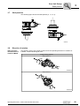
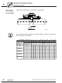
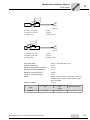
4.9
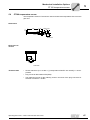
Mounting a motor with motor adapter
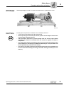
Motor adapters [1] are available for mounting IEC / NEMA motors to P.MC series industrial gear units.
For mounting the coupling [2], refer to the notes in Sec. "Mounting couplings".
The figures below show the basic structure of the motor adapter.
[1]
[2]
58054AXX
[1] Motor adapter
[2] Coupling
[1]
[2]
58055AXX
[1] Motor adapter
[2] Coupling
42
Operating Instructions – P.MC.. Industrial Gear Unit Series
Installation / Assembly
Mounting a motor with motor adapter
4
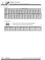
When selecting a motor, take into account the permitted motor weight, the gear unit
mounting position and the type of gear unit mounting according to the following
tables.
The following applies to all tables:
GM = Motor weight
GG = Gear unit weight
Industrial Gear Unit Series
Type of Mounting
MC.PL..
MC.RL..
Foot mounting
GM ≤ GG
GM ≤ GG
Shaft mounted
design
GM ≤ 0.5GG
GM ≤ GG
Flange mounting
GM ≤ 0.5GG
GM ≤ GG
Industrial Gear Unit Series
Type of Mounting
MC.RV..
MC.PV..
Foot mounting
GM ≤ 1.5GG
GM ≤ GG
Shaft mounted
design
GM ≤ GG
GM ≤ GG
Flange mounting
GM ≤ GG
GM ≤ 0.75GG
Industrial Gear Unit Series
Type of Mounting
MC.PE..
MC.RE..
Foot mounting
GM ≤ GG
GM ≤ 1.5GG
Shaft mounted
design
GM ≤ GG
GM ≤ GG
Flange mounting
GM ≤ GG
GM ≤ GG
These tables are for stationary operation only. Contact SEW-EURODRIVE if the
gear unit moves while in operation (e.g. travel drive).
Operating Instructions – P.MC.. Industrial Gear Unit Series
43
4
Installation / Assembly
Mounting a motor with motor adapter
Permitted motors
that can be
mounted
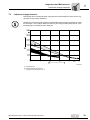
When mounting motors, observe the center of gravity of the motor and the weight of the
motor.
[1]
X
Fq
58517AXX
[1] Center of gravity of the motor
These tables only apply to the following correlation of motor size / weight Fq and
dimension "x".
IEC motor size
NEMA motor size
Fq max [N]
X [mm]
132S
213/215
579
189
132M
213/215
677
208
160M
254/286
1059
235
160L
254/286
1275
281
180M
254/286
1619
305
180L
254/286
1766
305
200L
324
2354
333
225S
365
2943
348
225M
365
3237
348
250M
405
4267
395
280S
444
5984
433
280M
445
6475
433
315S
505
8142
485
315M
505
315L
8927
485
11772
555
The maximum approved weight of the attached motor Fq has to be reduced in a linear
manner if the center of gravity distance x is increased. Fq max cannot be increased if the
center of gravity distance is reduced.
Please contact SEW-EURODRIVE in the following cases:
44
•
If a motor adapter is removed, re-alignment is necessary.
•
When retrofitting motor adapters with a cooling air fan (not for motors of sizes 132S
and 132M).
Operating Instructions – P.MC.. Industrial Gear Unit Series
Mechanical Installation Options
Important installation instructions
5
Mechanical Installation Options
5.1
Important installation instructions
5
•
Strictly observe the safety notes in the individual sections.
•
Disconnect the motor from the power supply before starting work on couplings and secure it against unintentional restart.
•
Work on the gear unit only when the machine is not in use.
•
Never drive couplings, pinions, etc. onto the shaft end by hitting them with a
hammer (damage to bearings, housing and the shaft!).
•
In the case of belt pulleys, make sure the belt is tensioned correctly in accordance with the manufacturer’s instructions.
•
Input and output elements such as couplings must be equipped with a touch
guard!
•
Power transmission elements should be balanced after installation and must
not give rise to excessive radial or axial forces.
•
Only use a mounting device for installing input and output elements. Use the
center bore and the thread on the shaft end for positioning.
Assembly is easier if you first apply lubricant to the output element or heat it up briefly
(to 80 ... -100 °C).
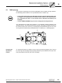
Installation note
for couplings
Adjust the following misalignments when mounting couplings:
a) Axial misalignment (maximum and minimum clearance)
b) Axle misalignment (concentric running fault)
c) Angular misalignment
a)
b)
c)
03356AXX
Operating Instructions – P.MC.. Industrial Gear Unit Series
45
5
Mechanical Installation Options
Important installation instructions
Note:
The following methods for measuring angular and axial misalignment are important for complying with the mounting tolerances specified in Sec. "Mounting of
couplings"!
Measuring
angular misalignment with a feeler
gauge
The following figure shows the measurement for angular misalignment (α) using a feeler
gauge. When using this method, an accurate result is only achieved when the deviation
of the coupling faces is eliminated by turning both coupling halves by 180° and the average value is then calculated from the difference (a1– a2).
a1
a
D
α
a2
52063AXX
Measuring
angular misalignment using a
micrometer dial
The following figure shows the measurement for angular misalignment using a micrometer dial. This measuring method provides the same result as described under "Measuring angular offset with a feeler gauge" if the coupling halves are rotated together, for
instance with one coupling pin, so that the needle of the micrometer dial does not move
noticeably on the measuring surface.
a1
a
D
α
f2
f1
a2
52064AXX
A prerequisite for this measuring method is that there is no axial clearance in the shaft
bearings when the shafts rotate. If this condition is not fulfilled, the axial play between
the faces of the coupling halves must be eliminated. As an alternative, you can use two
micrometer dials positioned on the opposite sides of the coupling (to calculate the difference of the two micrometer dials when rotating the coupling).
46
Operating Instructions – P.MC.. Industrial Gear Unit Series
Mechanical Installation Options
Important installation instructions
Measuring offset
misalignment
using straightedge and
micrometer dial
5
The following figure shows the measurement for offset misalignment using a straightedge. Permissible values for eccentricity are usually so small that the best measurement
results can be achieved with a micrometer dial. If you rotate one coupling half together
with the micrometer dial and divide the deviation by two, the micrometer dial will indicate
the deviation and as a result the misalignment (dimension "b"), which includes the offset
misalignment of the other coupling half.
b
f2
f1
52065AXX
Measuring offset
misalignment
using a micrometer dial
The following figure shows the measurement for offset misalignment using a more
accurate measuring method. The coupling halves are rotated together without the
tip of the micrometer dial moving on the measuring surface. The offset misalignment is
obtained by dividing the deviation indicated on the micrometer dial (dimension "b").
b
f2
f1
52066AXX
Operating Instructions – P.MC.. Industrial Gear Unit Series
47
Mechanical Installation Options
Installing couplings
5
5.2
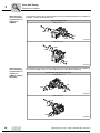
Installing couplings
ROTEX coupling
[1]
[2]
[1]
51663AXX
[1] Coupling hub
[2] Ring gear
The low-maintenance, elastic ROTEX coupling is capable of compensating radial and
angular misalignment. Careful and exact alignment of the shaft ensures long service life
of the coupling.
48
Operating Instructions – P.MC.. Industrial Gear Unit Series
Mechanical Installation Options
Installing couplings
Mounting the coupling halves onto
the shaft
5
L1
ØdH
ØdW
G
s
s
E
51689AXX
The shaft distance must be strictly observed (dimension E) to ensure axial play of
the coupling.
Mounting dimensions
dW
[mm]
L1 (aluminum / cast
iron / ductile iron)
[mm]
Locking screw
Coupling size
E
[mm]
s
[mm]
dH
[mm]
L1 (steel)
[mm]
G
Tightening torque
[Nm]
14
13
1.5
10
7
-
-
M4
2.4
19
16
2
18
12
26
-
M5
4.8
24
18
2
27
20
30
-
M5
4.8
28
20
2.5
30
22
34
-
M6
8.3
38
24
3
38
28
40
60
M8
20
42
26
3
46
36
46
70
M8
20
48
28
3.5
51
40
50
76
M8
20
55
30
4
60
48
56
86
M10
40
65
35
4.5
68
55
63
91
M10
40
75
40
5
80
65
72
104
M10
40
90
45
5.5
100
80
83
121
M12
69
100
50
6
113
95
92
-
M12
69
110
55
6.5
127
100
103
-
M16
195
125
60
7
147
120
116
-
M16
195
140
65
7.5
165
135
127
-
M20
201
160
75
9
190
160
145
-
M20
201
180
85
10.5
220
185
163
-
M20
201
Operating Instructions – P.MC.. Industrial Gear Unit Series
49
Mechanical Installation Options
Installing couplings
5
Mounting dimensions of ROTEX
coupling in motor
adapter
Tighten the set screws (A) to avoid axial play of the coupling.
E
A
A
L1
L2
L3
51696AXX
The mounting dimensions specified in the following table only apply to mounting a
ROTEX coupling in a motor adapter. They apply to all gear unit versions and gear ratios.
The shaft distance must be strictly observed (dimension E) to ensure axial play of
the coupling.
ROTEX coupling
size
E
[mm]
L1
[mm]
L2
[mm]
L3
[mm]
132
20
0
–17
3
R38/45
160
24
1
0
25
R42/55
180/200
26
–1
0
25
R48/60
225
28
0
–3
25
R55/70
225
30
0
–5
25
R65/75
250/280
35
0
–10
25
R75/90
315
40
0
–15
25
R90/100
315
45
–20
0
25
R28/38
50
Mounting dimensions
IEC motor size
Operating Instructions – P.MC.. Industrial Gear Unit Series
Mechanical Installation Options
Installing couplings
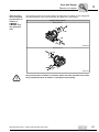
Nor-Mex
coupling, types G
and E
5
The low-maintenance Nor-Mex couplings types G and E are torsionally flexible couplings capable of compensating axial, angular, and radial misalignments. Torque is
transmitted via an elastic element with high damping properties, which is also oil and
heat resistant. The couplings can be used for either direction of rotation and can be
mounted in any position. The design of the Nor-Mex coupling type G allows to replace
the elastic element [5] without misalignment of the shafts.
Nor-Mex E
Nor-Mex G
[1]
[2]
[6]
[1]
[5]
[4]
[3]
[1]
[2]
51667AXX
[1] Coupling hub
[1] Socket head screw
[2] Elastic element
[2] Tooth lock washer
[3] Claw ring
[4] Flange hub
[5] Elastic element
[6] Coupling hub
Operating Instructions – P.MC.. Industrial Gear Unit Series
51
5
Mechanical Installation Options
Installing couplings
Mounting instructions, mounting
dimensions for
Nor-Mex G coupling
After having mounted the coupling halves, ensure that the recommended play (dimension S2 for type G, dimension S1 for type E) and the overall length (dimension LG for type
G and dimension LE for type E) corresponds with the dimensions given in the following
tables. Accurate alignment of the coupling (→ Sec. 'Mounting tolerances') ensures long
service life.
IE
IG
S2
LG
51674AXX
Nor-Mex G
Coupling size
52
Mounting dimensions
lE
[mm]
lG
[mm]
LG
[mm]
Permitted deviation S2
[mm]
Weight
[kg]
82
40
40
92
12±1
1.85
97
50
49
113
14±1
3.8
112
60
58
133
15±1
5
128
70
68
154
16±1
7.9
148
80
78
176
18±1
12.3
168
90
87
198
21±1.5
18.3
194
100
97
221
24±1.5
26.7
214
110
107
243
26±2
35.5
240
120
117
267
30±2
45.6
265
140
137
310
33±2.5
65.7
295
150
147
334
37±2.5
83.9
330
160
156
356
40±2.5
125.5
370
180
176
399
43±2.5
177.2
415
200
196
441
45±2.5
249.2
480
220
220
485
45±2.5
352.9
575
240
240
525
45±2.5
517.2
Operating Instructions – P.MC.. Industrial Gear Unit Series
Mechanical Installation Options
Installing couplings
5
Mounting dimensions of the NorMex E coupling
IE
IE
S1
LE
51674AXX
Nor-Mex E
Coupling size
Mounting dimensions
lE
[mm]
LE
[mm]
Permitted deviation S1
[mm]
Weight
[kg]
67
30
62.5
2.5± 0.5
0.93
82
40
83
3± 1
1.76
97
50
103
3± 1
3.46
112
60
123.5
3.5± 1
5
128
70
143.5
3.5± 1
7.9
148
80
163.5
3.5± 1.5
12.3
168
90
183.5
3.5± 1.5
18.4
194
100
203.5
3.5± 1.5
26.3
214
110
224
4± 2
35.7
240
120
244
4± 2
46.7
265
140
285.5
5.5± 2.5
66.3
295
150
308
8± 2.5
84.8
330
160
328
8± 2.5
121.3
370
180
368
8± 2.5
169.5
415
200
408
8± 2.5
237
480
220
448
8± 2.5
320
575
240
488
8± 2.5
457
Operating Instructions – P.MC.. Industrial Gear Unit Series
53
5
Mechanical Installation Options
Installing couplings
Mounting dimensions of the NorMex G coupling in
the motor adapter
Tighten the set screws (A) to avoid axial play of the coupling.
S2
A
A
L2
L1
L3
51672AXX
The mounting dimensions specified in the following table only apply to mounting a NorMex coupling in a motor adapter.
NOR-MEX G.. Coupling size
IEC motor size
Gear unit size
Gear ratio i
97
112
128
148
168
194
214
160
160/180
200
225
250/280
280/315
315
Mounting
dimensions
[mm]
All
All
S2
14
14
15
16
18
21
24
26
L3
3
25
25
25
25
25
25
25
MC3R02
i = 14 ... 63
L2
-
5
5
5
10
2
1
0
L1
-
6
5
4
–3
2
0
–1
MC3R05
i = 14 ... 63
MC3R08
i = 14 ... 63
Other P.MC..
i = 7.1 ... 112
54
97
132
L2
-
5
5
5
4
2
5
0
L1
-
6
5
4
3
2
–4
–1
L2
-
5
5
5
4
2
1
5
L1
-
6
5
4
3
2
1
–6
L2
–5
5
5
5
4
2
1
0
L1
–6
6
5
4
3
2
0
–1
Operating Instructions – P.MC.. Industrial Gear Unit Series
Mechanical Installation Options
FXM backstop
5.3
5
FXM backstop
The purpose of a backstop is to prevent undesirable reverse rotation. During operation,
the backstop permits rotation in one specified direction of rotation only.
•
Do not start up the motor in the blocking direction. Be sure that the motor power supply is correctly attached so that the motor rotates in the required direction. Operating the motor in the direction that is blocked could destroy the
backstop.
•
Consult SEW-EURODRIVE if you want to change the blocking direction.
The maintenance-free FXM type backstop is a centrifugally operated backstop with
sprags that lift off. Once the lift-off speed is reached, the sprags completely lift off from
the contact surface of the outer ring. The backstop is lubricated with gear oil. An arrow
on the gearcase indicates the permitted direction of rotation [1] (→ following figure).
[1]
[1]
58057AXX
Changing the
direction of
rotation
To change the direction of rotation, turn the inner ring with the sprags by 180°. Pull out
the inner ring with the sprags using a pulling-off device (not included in the scope of delivery) and replace turned by 180° (see next page).
Operating Instructions – P.MC.. Industrial Gear Unit Series
55
Mechanical Installation Options
FXM backstop
5
... with backstop
mounted outside
the gear unit
[7]
[1]
[4]
[2]
[3]
51640AXX
[1] Outer ring
[2] Retaining screws
[3] Circlip
[4] Inner ring with cage and sprags
1. Drain the gear oil (→ Sec."Inspection and Maintenance").
2. Loosen the retaining screws [2] of the backstop.
3. Remove the outer ring [1]. To facilitate dismounting, slightly turn the outer ring [1] in
freewheeling direction.
4. Remove circlip [3], and inner ring with cage and sprags [4].
5. Turn the inner ring [4] with the sprags by 180° and replace the parts in reverse order.
When mounting the backstop, do not apply pressure to the cage with the sprags but
to the inner ring [4] only. Use the threaded holes on the inner ring [4] for mounting.
6. Fix the inner ring [4] with the circlip [3] in axial direction. Mount the outer ring [1] using
the retaining screws [2]. Observe the tightening torques specified in the following table:
Screw size
Tightening torque [Nm]
M5
6
M6
10
M8
25
M10
48
M12
84
M16
206
M20
402
M24
696
M30
1420
7. Alter the direction arrow on the gearcase.
8. Refill the gear oil (→ Sec. 9). Check the oil level.
9. After mounting, check that the backstop runs smoothly.
56
Operating Instructions – P.MC.. Industrial Gear Unit Series
Mechanical Installation Options
FXM backstop
... with backstop
mounted inside the
gear unit
[9]
[4]
[1]
5
[2]
[7] [6]
[5]
[3]
[8]
51645AXX
[1] Outer ring
[5] Sleeve
[2] Circlip
[6] Bearing cover
[3] Inner ring with cage and sprags
[7] Shims
[4] Supporting ring
[8] Pulling device
1. Drain the gear oil (→ Sec."Inspection and Maintenance").
2. Remove bearing cover [6], shims [7] and sleeve [5]. It is important that shims [7] and
sleeve [5] between bearing cover [6] and outer ring [1] are not mixed up because they
must be assembled in the correct order.
3. Remove the circlip [2] from the input shaft.
4. Remove the inner ring with the cage and wedge elements [3] using a suitable pulling
device [8]. Use the threaded holes on the inner ring [3] for mounting.
5. Turn the inner ring [3] with the sprags by 180° and replace the parts in reverse order.
When mounting the backstop, do not apply pressure to the cage with the sprags but
to the inner ring [3] only.
6. When mounting the backstop, turn it in freewheeling direction so that the sprags
move into the outer ring.
7. Fix the inner ring [3] with the circlip [2] in axial direction.
8. Mount the sleeve [5], shims [7] and bearing cover [6] in reverse order.
9. Alter the direction arrow on the gearcase.
10.Refill the gear oil (→ Sec. 9). Check the oil level.
11.After mounting, check that the backstop runs smoothly.
Operating Instructions – P.MC.. Industrial Gear Unit Series
57
Mechanical Installation Options
SHP shaft end pump
5
5.4
SHP shaft end pump
Usage
The maintenance-free shaft end pump SHP.. can be used to lubricate gear unit parts of
gear unit sizes MC04 to MC09 that are not submerged in the oil bath. The shaft end
pump can be operated in both directions of rotation.
A minimum input speed is necessary for correct working of the shaft end pump.
Therefore, always consult SEW-EURODRIVE in the event of variable input speeds
(e.g. with inverter controlled drives) or when changing the input speed range of
an already delivered gear unit with shaft end pump.
Pump position
The pump is mounted externally to the gear unit and is directly driven by the input shaft
or intermediate shaft of the gear unit. A high reliability of the pump function is ensured
in this way. The pump position depends on the following factors:
•
Number of gear unit stages
•
Gear unit type (helical or bevel-helical)
•
Shaft position of the gear unit
•
Output shaft type
Check for interference of the shaft end pump with other surrounding structures.
58
Operating Instructions – P.MC.. Industrial Gear Unit Series
Mechanical Installation Options
SHP shaft end pump
5
Shaft positions
23
131)
241)
14
031)
041)
MC2PS
• Solid shaft
MC3PS
• Solid shaft
1) The maximum permitted external loads on the output shaft are lower.
Shaft positions
03
04
MC2R
• Solid shaft
MC3RS
• Solid shaft
1) The maximum permitted external loads on the output shaft are lower.
Operating Instructions – P.MC.. Industrial Gear Unit Series
59
Mechanical Installation Options
SHP shaft end pump
5
Pump suction
•
It is essential that the gear unit is sufficiently lubricated from the very beginning!
•
Do not change the diameter of the tube / pipe connection!
•
Do not open the pressure line [PRE]!
•
If the shaft end pump does not build up pressure within 10 seconds after the
gear unit has been started, please contact SEW-EURODRIVE.
Shaft end pump
mounted on top
of the P.MC.V..
gear unit
Danger of dry-start with shaft end pump mounted on top of gear unit.
[1]
[1]
[2]
58058AXX
[1[ Separate oil filling plug on the intake pipe
[2] Oil flow monitor or optical oil flow indicator (not visible in the figure)
It is essential that the oil pump begins to pump oil as soon as the main motor begins to
rotate. If the pump does not begin to pump oil immediately, open the separate oil filling
plug [1] and pour in oil (1-4 liters). Once the oil begins to circulate (check with flow switch
or visual flow indicator [2]), close the separate oil filling plug.
This procedure is particularly important if the gear unit has been standing for a long period of time and there is air in the suction pipe and oil pump.
60
Operating Instructions – P.MC.. Industrial Gear Unit Series
Mechanical Installation Options
Oil heater
5.5
5
Oil heater
Oil heating is required to ensure lubrication at startup when the ambient temperature is
low (e.g. cold start of the gear unit).
Purpose and
basic design
The oil heater consists of three basic parts:
1. Resistor element in the oil bath ("Oil heater") with terminal box
2. Temperature sensor
3. Thermostat
[3]
[2]
[1]
58062AXX
[1] Oil heater
[2] Temperature sensor
[3] Thermostat
[3]
[3]
[2]
[1]
[1]
58059AXX
[1] Oil heater
[2] Temperature sensor
[3] Thermostat
Operating Instructions – P.MC.. Industrial Gear Unit Series
61
Mechanical Installation Options
Oil heater
5
[3]
[3]
[1]
[2]
[1]
58060AXX
[1] Oil heater
Activation / deactivation behavior
•
[2] Temperature sensor
[3] Thermostat
The oil heater is activated when the factory set temperature is reached. This temperature setpoint depends on the following factors:
– Forth splash / bath lubrication: on the pourpoint of the used oil
– For pressure lubricated units: on the temperature at which the oil viscosity
reaches a maximum of 2000 cSt
Switching point for splash / bath lubrication [°C]
ISO VG
680
460
320
220
150
100
Mineral oil
–7
–10
–15
–20
–25
–28
–30
–35
–40
–40
–45
Synthetic oil
Switching point for pressure lubrication [°C]
ISO VG
680
460
320
220
150
Mineral oil
+25
+20
+15
+10
+5
+15
+10
+5
0
Synthetic oil
•
100
–5
The oil heater is deactivated when the set temperature is exceeded by 8 to 10°C.
Thermostat and oil heater are usually installed on the gear unit and are ready for operation but without electrical connections. Therefore, do the following before startup:
1. Connect the resistor element ("Oil heater") to the power supply
2. Connect the thermostat to the power supply
Technical data
Gear unit size
Current consumption oil heater
Voltage supply
[W]
[VAC]
04 - 06
600
07 - 09
1200
See separate data sheet1)
1) Only use voltage specified in separate data sheet.
62
Operating Instructions – P.MC.. Industrial Gear Unit Series
Mechanical Installation Options
Oil heater
Electrical connection resistor
element
5
Wiring examples with 230 / 400 V supply voltage
N
N
L1
L1
57610AXX
1-phase
Voltage
230 V
Phase voltage
230 V
Mains voltage
400 V
Resistor element voltage
230 V
N
L1
L1
N
L2
L3
L3
L2
57611AXX
3-phase / star connection
Voltage
230/400 V
Phase voltage
230 V
Mains voltage
400 V
Resistor element voltage
230 V
L1
L3
L1
L2
L3
L2
57612AXX
3-phase / delta connection
Voltage
400 V
Mains voltage
400 V
Resistor element voltage
400 V
Operating Instructions – P.MC.. Industrial Gear Unit Series
63
5
Mechanical Installation Options
Oil heater
Basic structure of
thermostat
[1]
[2]
[7]
[3]
[4]
[6]
[5]
53993AXX
[1] Setting knob
[2] Degree of protection IP66 (IP54 in units with external reset)
[3] 2 x PG 13.5 for cable diameter 6 mm → 14 mm
[4] SPDT contact system, exchangeable
64
[5] Capillary tube length up to 10 m
[6] Stainless steel corrugated tube
[7] Polyamide housing
Operating Instructions – P.MC.. Industrial Gear Unit Series
Mechanical Installation Options
Oil heater
5
Basic structure of
thermostat
Thermostat RT
Ambient temperature
– 50 °C to +70°C
[2]
4
[1]
1
Connection diagram
2
[1] Cable
[2] SPDT
Alternating current:
AC-1: 10 A, 400 V
AC-3: 4 A, 400 V
AC-15: 3 A, 400 V
Connection data
A
0.48
0.5
0.4
Direct current:
DC-13: 12 W, 230 V
0.3
0.2
Contact material:
AgCdO
0.055
12 W
0.1
20
40
60
80 100 120 140 160 180 200
230
V
25
Cable entry
2 PG 13.5 for cable diameter of 6 -14 mm
Degree of protection
IP66 acc. to IEC 529 and EN 60529, IP54 for units with external reset. The thermostat housing is
made of bakelite according to DIN 53470, the cover is made of polyamid.
A contactor must be used in the following cases:
•
3-phase voltage supply
•
2 heating rods
•
Current ratings exceed nominal values of thermostat
Operating Instructions – P.MC.. Industrial Gear Unit Series
65
Mechanical Installation Options
Oil heater
5
Adjusting the
setpoint
The setpoint is usually set at the factory. Proceed as follows for adjustment:
The range is set by using the setting knob [1] while at the same time reading the main
scale [2]. Use a tool if the thermostat is equipped with a cap. The differential is set using
the differential disc [3].
The size of the differential obtained for the relevant thermostat can be established by
comparing the set main scale value and the scale value on the differential disc with the
help of a nomogram.
[1]
[2]
2
1
4
[3]
53994AXX
[1] Setting knob
[2] Main scale
[3] Differential setting disc
1
30
2
°C
2
°C
3
4
3
25
5
20
7
6
7
8
10
9
5
10
8
[C]
0
-5
5
6
15
4
[A]
9
[B]
10
53992AXX
[A] Setting range
[B] Obtained differential
[C] Differential setting
66
Operating Instructions – P.MC.. Industrial Gear Unit Series
Mechanical Installation Options
PT100 temperature sensor
5.6
5
PT100 temperature sensor
The temperature sensor PT100 can be used to measure the temperature of the oil in the
gear unit.
Dimensions
R1/2
PG9, PG11
35
34
24
Ø8
150
50533AXX
Electrical connection
3
2
1
50534AXX
Technical data
•
Sensor tolerance ±(0.3 + 0.005 × t), (corresponds to DIN IEC 751 class B), t = oil temperature
•
Plug connector DIN 43650 PG9 (IP65)
•
The tightening torque for the retaining screw in the back of the plug connector for
electrical connection = 25 Nm
Operating Instructions – P.MC.. Industrial Gear Unit Series
67
Mechanical Installation Options
Fan
5
5.7
Fan
Make sure air intake vents are not blocked or covered!
A fan can be mounted if the projected thermal power of the gear unit is exceeded. A fan
can be retrofitted if the ambient conditions change after having installed the gear unit.
The direction of rotation of the gear unit does not influence the operation of the fan.
B1
A1
Ød3
A1
B1
30°
Y4
Y1
58061AXX
68
Gear unit
type
A1
B1
Y4
Y1
PMC3RL..02
158
PMC3RL..03
PMC3RL..04
Air intake
160
70
100
178
165
82
112
131
198
185
90
120
131
PMC3RL..05
213
195
95
125
156
PMC3RL..06
232
220
100
130
156
PMC3RL..07
262
230
105
135
156
PMC3RL..08
297
255
105
135
198
PMC3RL..09
332
265
110
140
226
∅ d3 [mm]
[mm]
Angle
109
30°
Operating Instructions – P.MC.. Industrial Gear Unit Series
Mechanical Installation Options
Flow switch
5.8
5
Flow switch
Usage
The flow switch is an electrical switch used for controlling the correct functioning of a
pressure lubrication system (→ shaft end pump; → motor pump) by checking the oil
flow.
In deliveries since March 1, 2005, the flow switch is a standard feature for all gear units
supplied with
•
Motor pump
•
A shaft end pump with an oil flow rate of 8.5 l/min or higher.
Shaft end pumps with a flow rate below 8.5 l/min are equipped only with a visual flow
indicator (→ Visual flow indicator) as standard (as of 2006).
If the flow rate exceeds 8.5 l/min, the gear unit is delivered with a visual flow indicator
and flow switch (as of 2006).
Selection
SEW-EURODRIVE selects the flow switch. As standard, a flow switch of the type DWR-20 is used. All the following technical data refer to this type.
Function
The oil flow pushes against a circular plate attached to a pendulum. The pendulum,
which is regulated by a spring, moves on its pivot. A magnet attached to the end of the
pendulum operates a movable reed contact. The switch unit itself is separated from the
oil.
The flow switch has two switching points:
1. Switching point HIGH (lower limit of flow rate) → contact closed - ON
2. Switching point LOW (upper limit of flow rate) → contact closed - OFF
Operating Instructions – P.MC.. Industrial Gear Unit Series
69
Mechanical Installation Options
Flow switch
5
Dimensions
d
SW
60.0 ±1
M-SW 32
I
I
50.0
55964AXX
d
(inner thread)
NW
(rated width)
I
SW
Z
Z
A+B+C
A+B
30
50
L
H
Z
C
D
D
D
50
19
109
66
[mm]
Material
Dimension
R¾"
20
11
Material abbreviations:
A = Brass
B = Nickel-plated brass
C = Stainless steel
D = Stainless steel / PVC
For determining the exact position of the flow switch, refer to the order-specific dimension drawing.
Electrical
connection
[1]
[2]
[3]
56027AXX
[1] Brown
[3] Yellow / green
[2] Blue
70
Operating Instructions – P.MC.. Industrial Gear Unit Series
Mechanical Installation Options
Flow switch
5
[1]
[2]
[3]
[4]
[5]
[6]
56028AXX
[1] Switching point HIGH
[4] Blue
[2] Switching point LOW
[5] Brown
[3] Setting range
[6] Yellow / green
[1]
[2]
[3]
[4]
[5]
[6]
56029AXX
[1] Switching point HIGH
[4] Blue
[2] Switching point LOW
[5] Brown
[3] Setting range
[6] Yellow / green
Connection data:
230 V; 1,5 A; 80 W, 90 VA max
Degree of protection:
IP 65
Maximum temperature of medium:
110 ° C
Maximum ambient temperature:
70 ° C
Maximum working pressure:
25 bar
Length of connecting cable:
1.5 m
Switch:
Switch can be used as normally closed or
normally open contact; SPDT switch available on request
Switch hysteresis:
ca. 5 %
Type
Switching point range
ON
Switching point range
OFF
Maximum flow rate
[l/min]
DW-R-20
8.5 - 12.0
Operating Instructions – P.MC.. Industrial Gear Unit Series
6.6 - 11.0
80
71
Mechanical Installation Options
Visual flow indicator
5
5.9
Visual flow indicator
[2]
[3]
[2]
[1]
[2]
57682AXX
[1] Oil flow direction
[2] Glass
[3] Oil distributor block
Usage
The visual flow indicator is a simple method of checking the functioning of a pressure
lubrication system by visually checking the oil flow. The visual flow indicator is a standard feature in all gear units with oil pump (as of 2006).
Gear units with oil pump and a flow rate above 8.5 l/min are equipped with an electrical
flow switch and visual flow indicator (as of 2006).
Function
The oil flow can be seen behind the glass [2]. If no oil flows and / or if there are air bubbles in the oil, check the function of the pump and suction pipes with connections.
It is easier to see the oil flow when the glasses [2] are clean and bright light is used on
the other side of the oil distribution block.
72
Operating Instructions – P.MC.. Industrial Gear Unit Series
Mechanical Installation Options
Oil expansion tank and oil riser pipe
5.10
5
Oil expansion tank and oil riser pipe
An oil expansion tank or an oil riser pipe may be necessary for vertical output shaft positions. Please refer to the order documents for information.
5.11
Connecting the oil / water cooling system
Follow the instructions in the separate manufacturer’s documentation when connecting
the oil / water cooling system.
5.12
Connecting the oil / air cooling system
Follow the instructions in the separate manufacturer’s documentation when connecting
the oil / air cooling system.
5.13
Connecting the motor pump
Follow the instructions in the separate manufacturer’s documentation when connecting
the motor pump.
Operating Instructions – P.MC.. Industrial Gear Unit Series
73
I
6
Startup
Gear unit startup
0
6
Startup
6.1
Gear unit startup
Before startup
MAX
74
•
It is essential to adhere to the safety notes in Sec. "Safety Notes."
•
It is essential that there is no open fire or risk of sparks when working on the
gear unit.
•
Take preventive measures to protect people from the solvent vapors generated by the vapor phase inhibitor!
•
Before startup, check that the oil level is correct. For lubricant fill quantities,
refer to Sec. "Lubricants."
•
For gear units with long-term protection: Replace the screw plug on the location indicated by the breather plug (Position → Sec. "Mounting Positions").
•
Check the surface temperature before you perform maintenance on the gear
unit or refill the gear unit oil. Risk of burns (hot oil in the gear unit).
•
Remove dust and dirt from the gear unit surface.
•
For gear units with long-term protection: Remove the gear unit from the sea-worthy protection box.
•
Remove the corrosion protection agent from the gear unit parts. Make sure gaskets,
sealing surfaces and sealing lips are not damaged by mechanical abrasion, etc.
•
Before filling the gear unit with the correct oil grade and volume, drain the remaining
amount of protection oil. To do so, unscrew the oil drain plug and drain the remaining
protection oil. Thread the oil drain plug back in place.
•
Remove the oil filling plug (Position → Sec. "Mounting Positions"). Use a funnel to fill
the oil (filter mesh max. 25 μm). Fill the gear unit with the correct oil grade and volume
(→ Sec. "Nameplate"). The oil volume specified on the nameplate of the gear unit is
an approximate value. The mark on the dipstick is the decisive indicator of the
correct oil level. Check for correct oil level (= below the "max" mark on the dipstick)
using the oil dipstick. After having filled the oil, replace the oil filling plug.
•
For industrial gear units with steel oil expansion tanks (→ section 6.3 'Startup of MC
industrial gear units with steel oil expansion tanks')
•
For gear units with oil sight glass (sec. 7.3): Control whether the oil level is correct with a visual inspection (= oil can be seen through oil sight glass).
•
Ensure that rotating shafts as well as couplings are equipped with suitable protective
covers.
•
If the gear unit has a motor pump, check for proper functioning of the pressure lubricating system. Make sure that monitoring devices are connected properly.
•
After an extended period of storage (max. two years), have the gear unit operate
without load with the correct oil fill (→ Sec. "Nameplate"). This way, the correct functioning of the lubricating system and particularly the oil pump is ensured.
•
If the gear unit is equipped with a fan on the input shaft, check for free air intake within
the specified angle (→ Sec. "Fan").
MIN
Operating Instructions – P.MC.. Industrial Gear Unit Series
Startup
Startup of gear units with long-term protection
I
6
0
Running-in
period
SEW-EURODRIVE recommends running-in the gear unit as the first phase of startup.
Increase the load and speed of revolutions in two to three steps up to maximum level.
The running-in phase takes approx. 10 hours.
Check the following points during the run-in phase:
•
Verify the power values specified on the nameplate because their frequency may be
a decisive factor for the service life of the gear unit.
•
Does the gear unit run smoothly?
•
Are there vibrations or unusual running noises?
•
Are there signs of leakage (lubricants) on the gear unit?
For further information and troubleshooting, refer to the "Malfunctions" section.
6.2
Startup of gear units with long-term protection
Adhere to the following points for gear units with long-term protection:
Anti-corrosion
agent:
Ensure sufficient ventilation when using solvents. There is a risk of explosion. No
open flames.
Risk of material damage.
Do not let the solvent come into contact with the sealing lips of the oil seals.
Remove the corrosion protection agent from the gear unit parts. Make sure gaskets,
sealing surfaces and sealing lips are not damaged by mechanical abrasion, etc.
Oil level
Since the gear units under "long-term protection" are delivered complete with oil, the
correct oil volume and oil level should be checked before startup.
→ Correct the oil level to the appropriate fill level.
Breather plug:
Replace the corresponding screw plug by the enclosed breather plug.
Operating Instructions – P.MC.. Industrial Gear Unit Series
75
I
6
Startup
Startup of gear units with backstop
0
6.3
Startup of gear units with backstop
Ensure that the direction of rotation of the motor is correct for gear units with
backstop.
6.4
Shutting down the gear unit
Turn off the drive unit. Prevent the drive unit from unintentionally starting up.
Put an information sign near the ON switch.
If the gear unit will not be operated for an extended period of time, you must activate it
regularly at intervals of approx. 2-3 weeks.
If the gear unit will not be operated for a period longer than nine months, additional
corrosion protection is required:
•
Corrosion protection for the interior of gear units with splash or oil bath
lubrication:
•
•
•
Fill the gear unit up to the breather plug with the oil grade specified on the nameplate.
Set the planetary gear unit in no-load running operation for a short period of time.
Exterior corrosion protection:
•
•
•
Clean the surfaces.
Grease the shaft around the sealing lip to separate the sealing lip of the oil seal
and the corrosion protection.
Apply a wax-based protective coating to shaft ends and unpainted surfaces as
corrosion protection.
Refer to the "Startup" section before restarting the gear unit.
76
Operating Instructions – P.MC.. Industrial Gear Unit Series
Inspection and Maintenance
Shutting down the gear unit
7
7
Inspection and Maintenance
•
Strictly observe the safety notes in the individual sections.
•
All maintenance work must be carried out carefully by qualified personnel.
•
All maintenance work on the gear unit and additional equipment must only be
carried out when the machine is not in use. Prevent the drive unit from starting
up unintentionally (for example, by locking the keyswitch or removing the fuses from the power supply). Attach an information sign near the ON switch to
warn that the gear unit is being worked on.
•
Use only OEM spare parts according to the delivered spare parts lists.
•
If you remove the gearcase cover, you must apply new sealing compound to
the sealing surface. Else the sealing properties of the gear unit might be impaired. It is essential to contact SEW-EURODRIVE in this case.
•
Prevent foreign objects from entering into the gear unit during the following
work.
Danger of burns
Touching the gear unit when it has not been cooled will result in burns.
Never touch the gear unit during operation or in the cool down phase once the unit has
been switched off.
Operating Instructions – P.MC.. Industrial Gear Unit Series
77
Inspection and Maintenance
Inspection and maintenance intervals
7
7.1
Inspection and maintenance intervals
Maintenance interval
•
•
What to do?
•
Check the housing temperature:
– with mineral oil: max 90 °C
– with synthetic oil: max. 110 °C
•
•
Check gear unit noise
Check gear unit for signs of leakage
•
•
Checking the oil level
Check the oil: If the gear unit is operated outdoors or in
humid conditions, check the water content of the oil. The
water content must not exceed 0.05 % (500 ppm).
Fill labyrinth seals with grease. Use about 30 g grease per
grease nipple.
Clean breather plug
Daily
Every 3000 hours of operation, at
least every 6 months:
•
•
•
•
Depending on the operating conditions, at the latest every 12
months
•
•
•
•
•
Depending on the operating con- •
ditions, at the latest every 3 years
•
•
•
•
78
Varying (depending on external
factors)
Change the mineral oil (→ Sec. "Inspection and Maintenance")
Check whether retaining screws are tightly secured
Check contamination and condition of the oil / air cooling
system
Check the condition of the oil / water cooling system
Clean oil filter, replace filter element if necessary
Change the synthetic oil (see Sec. "Inspection and Maintenance")
Touch up or renew the surface / anticorrosion coating
Clean the gearcase surface and fan
Check the oil heater:
• Are all connection cables and terminals tightened
securely and free from corrosion?
• Clean incrusted elements (e.g. heating element) and
replace, if required (→ Sec. "Inspection and Maintenance").
Operating Instructions – P.MC.. Industrial Gear Unit Series
Inspection and Maintenance
Lubricant change intervals
7.2
7
Lubricant change intervals
Change the oil more frequently when using special versions subject to more severe / aggressive environmental conditions!
Mineral CLP lubricants and synthetic polyalphaolefin-based (PAO) lubricants are used
for lubrication. The synthetic lubricant CLP HC (according to DIN 51502) shown in the
following figure corresponds to the PAO oils.
62087AXX
(1) Operating hours
(2) Sustained oil bath temperature
• Average value per oil type at 70 °C
Operating Instructions – P.MC.. Industrial Gear Unit Series
79
Inspection and Maintenance
Checking the oil level
7
7.3
Checking the oil level
•
Do not mix different synthetic lubricants and do not mix synthetic with mineral
lubricants.
•
The positions of the oil level plug, drain plug, and breather valve depends on
the mounting position. Refer to the diagrams of the mounting positions.
•
Mineral oil is used as standard lubricant.
1. Work on the gear unit only when the machine is not in use.
2. Secure the drive unit against unintentional power-up.
Wait until the gear unit has cooled off - Danger of burns!
3. For gear units with oil dipstick:
•
•
•
Unscrew the oil dipstick and remove it.
Clean the oil dipstick and re-insert it into the gear unit (do not screw in tightly).
Remove dipstick again and check oil level. Correct, if necessary. The oil level is
correct when it is between the oil level mark (= maximum oil level) and the end of
the dipstick (= minimum oil level).
4. For gear units with oil sight glass (option):
•
7.4
Visually check for correct oil level (= middle of oil sight glass).
Checking the oil consistency
1. Work on the gear unit only when the machine is not in use.
2. Secure the drive unit against unintentional power-up.
Wait until the gear unit has cooled off - Danger of burns!
3. Remove a little oil from the oil drain plug.
4. Check the oil consistency:
•
•
80
For more detailed information on checking the oil for water content and viscosity,
contact your lubricant manufacturer.
Contact SEW-EURODRIVE if the oil is heavily contaminated.
Operating Instructions – P.MC.. Industrial Gear Unit Series
Inspection and Maintenance
Changing the oil
7.5
7
Changing the oil
Procedure
•
When changing the oil, always refill the gear unit with the grade of oil that was
used before. Mixing oil of different grade is not permitted. Especially synthetic
oils may not be mixed with mineral oils or other synthetic oils. If you switch
from mineral oil to synthetic oil, or from synthetic oil on a certain basis to synthetic oil with a different basis, you will have to flush the gear unit thoroughly
with the new oil.
•
Refer to the lubrication table in section 9 to determine which oils from the various lubricant manufacturers can be used.
•
Information such as the oil grade, oil viscosity and required oil quantity is listed on the nameplate of the gear unit.
•
The oil volume specified on the nameplate is an approximate quantity. The
markings on the oil sight glass or dipstick are the decisive indicators for the
quantity of oil used to fill the unit.
•
Only change the oil when the gear unit is at operating temperature.
•
When changing the oil, flush the housing thoroughly with oil to remove oil
sludge, oil residue, and abrasion. Use the same grade of oil that is used to operate the gear unit. Viscous oil must first be heated up. Fill with fresh oil only
after all residues have been removed.
•
The position of the oil level plug, oil drain plug and the breather valve depends
on the mounting position. Refer to the diagrams of the mounting positions.
1. Work on the gear unit only when the machine is not in use.
2. Secure the drive unit against unintentional power-up.
Wait until the gear unit has cooled off - Danger of burns!
The gear unit must still be warm, otherwise the high viscosity of excessively cold oil will
make it more difficult to drain the oil correctly.
When changing the oil, clean the gearcase thoroughly to remove oil residues and abrasion. Use the same oil grade as for the operation of the gear unit.
If your gear unit is equipped with an oil expansion tank, let the gear unit cool off until it
reaches ambient temperature. The reason is that there might still be oil in the oil expansion tank which might leak through the oil filling hole!
Any dripping oil must be removed immediately with an oil binding agent.
3. Place a container underneath the oil drain plug.
Operating Instructions – P.MC.. Industrial Gear Unit Series
81
Inspection and Maintenance
Checking and cleaning the breather plug
7
4. Remove the oil filling plug, breather plug and oil drain plugs. When using a steel oil
expansion tank, also remove the air outlet screw on the air expansion tank. To drain
all the oil, blow air through the breather into the oil expansion tank. As a result, the
rubber membrane lowers and forces the remaining oil out. The lowering membrane
compensates the pressure, which facilitates filling the new oil.
5. Drain all the oil.
6. Screw in the oil drain plug.
7. Use a funnel to fill the oil (filter mesh max. 25 mm). Fill new oil of the same type as
the old oil via the oil filling plug (if you want to change the oil type, contact our customer service first).
– Fill the oil according to the volume specified on the nameplate (→ Sec. "Nameplate"). The oil volume specified on the nameplate is an approximate value. The
marks on the oil dipstick indicate the correct oil level.
– Check whether the oil level is correct using the oil dipstick.
8. Screw the oil level plug back in If your gear unit is equipped with a steel oil expansion
tank, also screw in the air outlet screw.
9. Screw in the breather plug.
10.Clean the oil filter, replace the filter element if necessary (when using an external oil
/ air or oil / water cooling system).
7.6
Checking and cleaning the breather plug
The breather plug must be cleaned if there is a layer of dust and also before the expiration of a minimum period of three months.
To do so, remove the breather plug, clean it with benzine or a similar cleaning agent,
and dry or blow the breather plug with compressed air. Prevent foreign objects from entering into the gear unit.
82
Operating Instructions – P.MC.. Industrial Gear Unit Series
Malfunctions
Customer service
8
8
Malfunctions
•
Strictly observe the safety notes in the individual sections.
•
For eliminating malfunctions, the gear unit and additional equipment must be
deactivated. Prevent the drive unit from starting up unintentionally (for
example, by locking the keyswitch or removing the fuses from the power
supply). Attach an information sign near the ON switch to warn that the gear
unit is being worked on.
Danger of burns
Touching the gear unit when it has not been cooled will result in burns.
Never touch the gear unit during operation or in the cool down phase once the unit has
been switched off.
Malfunctions that occur during the warranty period that require repair to the gear unit
may only be resolved by SEW-EURODRIVE.
After the warranty period has elapsed, we recommend that our customers contact our
customer service when malfunctions occur and the cause is not clear.
8.1
Customer service
Please have the following information to hand if you require the assistance of our
customer service:
•
Complete nameplate data
•
Type and extent of the problem
•
Time the problem occurred and any accompanying circumstances
•
Assumed cause
Operating Instructions – P.MC.. Industrial Gear Unit Series
83
Malfunctions
Gear unit malfunctions
8
8.2
Gear unit malfunctions
Malfunction
Possible cause
Remedy
Unusual, regular running
noise
A
B
A
Unusual, irregular running noise
Foreign bodies in the oil
•
Unusual noise in the area
of the gear unit mounting
Gear unit mounting has loosened
•
Meshing/grinding noise: Bearing damage
Knocking noise: Irregularity in the gearing
B
•
•
Operating temperature
too high
A
B
C
D
E
F
Too much oil
Oil too old
The oil is heavily contaminated
Gear units with fan: air intake opening /
gearcase contaminated
Shaft end pump defective
Malfunctions of oil / air or oil / water cooling system
A
B
C
D
E
F
Bearing point temperatures too high
A
B
C
D
A
Oil not enough
Oil too old
Shaft end pump defective
Bearing damaged
B
C
D
Oil leaking1)
• from cover plate
• from the gear cover
plate
• from bearing cover
• from mounting flange
• from output / input
end oil seal
A
Oil leaking
• oil drain plug
• breather plug
A
B
B
C
Gasket on cover plate / gear unit cover /
bearing cover / mounting flange leaks
Sealing lip of the oil seal turned up
Oil seal damaged / worn
B
C
C
Too much oil
Drive operated in incorrect mounting position
Frequent cold starts (oil foams) and / or
high oil level
Malfunctions of oil / air or
oil / water cooling system
Operating temperature at
backstop too high
A
A
B
Check the oil (→ Sec. "Inspection and Maintenance), replace bearings
Contact customer service
Check the oil (→ Sec. "Inspection and Maintenance")
Stop the drive, contact customer service
Tighten retaining screws and nuts to the specified
torque
Replace the damaged / defective retaining screws
or nuts
Check the oil level, correct if necessary (→ Sec.
"Inspection and Maintenance")
Check when the oil was changed last time; change
oil if necessary (→ Sec. "Inspection and Maintenance")
Change the oil (→ Sec. "Inspection and Maintenance")
Check the air intake opening and clean if necessary, clean gearcase
Check shaft end pump; replace if necessary
Observe the separate operating instructions for the
oil / water and oil / air cooling system.
Check the oil level, correct if necessary (→ Sec.
"Inspection and Maintenance")
Check when the oil was changed last time; change
oil if necessary (→ Sec. "Inspection and Maintenance")
Check shaft end pump; replace if necessary
Check bearing and replace if necessary, contact
customer service
Tighten the bolts on the respective cover plate and
observe the gear unit. If oil still leaks: Contact customer service
Vent the gear unit (→ Sec. "Mounting Positions")
Observe the gear unit. If oil still leaks: Contact customer service
Contact customer service
Correct the oil volume (→ Sec. "Inspection and
Maintenance)
Mount the breather plug correctly (→ order documents) and correct the oil level (→ nameplate)
Observe the separate operating instructions for the oil /
water and oil / air cooling system.
Damaged / defective backstop
•
•
Check backstop; replace if necessary
Contact customer service
1) During the run-in phase (24-hour run time), it is normal for small amounts of oil / grease to leak from the oil seal (see also DIN 3761).
84
Operating Instructions – P.MC.. Industrial Gear Unit Series
Lubricants
Guidelines for lubricant selection
9
Lubricants
9.1
Guidelines for lubricant selection
General
information
9
Unless a special arrangement is made, SEW-EURODRIVE delivers the P.MC.. gear
units without an oil fill.
•
Before startup, ensure that the gear unit is filled with the correct oil grade and
volume. You find the corresponding information on the gear unit nameplate
and the lubricant table in the following section.
•
The most important factors for selecting the lubricant are the oil grade and viscosity specified on the nameplate. The specified viscosity / oil grade are chosen for the operating conditions agreed upon in the contract. Any deviation
from these conditions requires consultation with SEW-EURODRIVE.
•
This lubricant recommendation in no way represents a guarantee as to the
quality of the lubricant delivered by each respective supplier. The lubricant
manufacturers are responsible for the quality of their products.
•
Do not mix different synthetic lubricants and do not mix synthetic with mineral
lubricants.
If you have selected synthetic oil because of the operating temperature or oil change intervals, SEW-EURODRIVE recommends polyalphaolefin-based oil (PAO).
Operating Instructions – P.MC.. Industrial Gear Unit Series
85
Lubricants
Lubricant table
9
9.2
Lubricant table
General
information
The lubricant table on the following page shows the permitted lubricants for SEWEURODRIVE gear units. Please refer to the following legend for the lubricant table.
Legend to the lubricant table
Abbreviations used, meaning of shading, and notes:
CLP
= Mineral oil
CLP PAO
= Synthetic polyalphaolefin
= Synthetic lubricant (= synthetic-based anti-friction bearing grease)
= Mineral lubricant (= mineral-based anti-friction bearing grease)
= Contact SEW-EURODRIVE
Ambient temperature
°C -40
0
+50
Notes on the lubricant table
86
•
The temperature ranges should be considered as guide values. The decisive
factor is the viscosity information on the nameplate.
•
Contact SEW-EURODRIVE if you operate the unit under extreme conditions,
such as cold, heat, or there have been changes to the operating conditions
since project planning.
Operating Instructions – P.MC.. Industrial Gear Unit Series
Operating Instructions – P.MC.. Industrial Gear Unit Series
P.MC..R..
P.MC..P..
0
-5
-20
-30
-35
-10
°C -40
0
+50
+40
+40
+40
+30
+25
+50
VG 220
CLP
VG 460
VG 680
CLP
VG 460
Mobilgear
XMP680
Mobil
SHC 634
Mobilgear
SHC XMP460
Mobilgear
XMP460
Omala
Oil HD 460
Omala
Oil F460
KLÜBER
GEM 1-680N
Klübersynth
GEM4-460N
KLÜBER
GEM 1-460N
Degol BG
Plus 680
Degol
PAS 460
Degol BG
Plus 460
Degol
PAS 320
Degol BG
Plus 320
KLÜBER
GEM 1-320N
Omala
Oil F320
Mobilgear
XMP320
Pinnacle
EP 460
Meropa 460
Pinnacle
EP 320
Meropa 320
Pinnacle
EP 220
Meropa 220
BP Energol Meropa 680
GX-XF 680
Enersyn
EP -XF 460
BP Energol
GX-XF 460
Enersyn
EP-XF 320
BP Energol
GX-XF 320
Enersyn
EP -XF 220
BP Energol
GX-XF 220
Degol BG
Plus 220
KLÜBER
GEM 1-220N
Enersyn
EP-XF 150
Enersyn
SG-XP 150
Degol
PAS 150
Degol
GS 150
Klübersynth
GEM4-150N
Degol
PAS 220
Omala
Oil F220
BP Energol
GX-XF 150
Degol BG
Plus 150
KLÜBER
GEM 1-150N
Klübersynth
Omala
Mobilgear
SHC XMP220 Oil HD 220 GEM4-220N
Mobilgear
XMP220
Mobil®
Mobilgear
Omala
Klübersynth
VG 320 SHC XMP320
Oil HD 320 GEM4-320N
Mobil
SHC 632
VG 320
CLP PAO
CLP
CLP PAO
CLP
VG 220
VG 150
CLP PAO
CLP PAO
VG 150
ISO VG
class
CLP
DIN (ISO)
Oil
Q8 Goya
NT 150
Q8 Goya
NT 220
Q8 Goya
NT 320
Q8 Goya
NT 460
Q8 Goya
NT 680
Renolin
Q8 ELGRECO
Unisyn CLP 460
460
Renolin
CLP460Plus
Renolin
Q8 ELGRECO
Unisyn CLP 320
320
Renolin
CLP320Plus
Renolin
Q8 ELGRECO
Unisyn CLP 220
220
Renolin
CLP220Plus
Renolin
Q8 ELGRECO
Unisyn CLP 150
150
Renolin
CLP150Plus
Q8
Tribol Optigear
1100 / 680 BM 680
Optigear
Synthetic X 460
Optigear
Synthetic A460
Tribol
1510/ 460
Tribol
1710/ 460
Optigear
BM 460
Tribol
1100 / 460
Alphamax
460
Optigear
Synthetic X 320
Optigear
Synthetic A320
Tribol
1710/ 320
Tribol
1510/ 320
Tribol
Optigear
1100 / 320 BM 320
Alphamax
320
Optigear
Synthetic X 220
Optigear
BM 220
Tribol
1710/ 220
Alphamax
220
Renolin
CLP680
Carter
SH 460
Carter
SH 320
Carter
SH 220
Carter
SH 150
TO T A L
Lubricants
Lubricant table
9
Lubricant table
01763198_4
87
Lubricants
Lubricant fill quantity
9
9.3
Lubricant fill quantity
The lubricant fill quantity is specified in your order document or on the nameplate.
The two gear units have a common oil chamber.
In case of a pivoted mounting position, refer to the oil fill quantity specified on the
nameplate.
9.4
Sealing grease
The below mentioned grease types can be used as
•
Sealing grease
•
Bearing grease for the lower LSS bearings for gear units with Drywell sealing system
SEW-EURODRIVE recommends the grease types listed in table below for operating
temperatures from – 30 °C to +100 °C.
Lubricating grease properties:
88
•
Contains EP additives
•
Hardness class NLGI2
Supplier
Oil
Aral
Aralub HLP2
BP
Energrease LS-EPS
Castrol
Spheerol EPL2
Chevron
Dura-Lith EP2
Elf
Epexa EP2
Esso
Beacon EP2
Exxon
Beacon EP2
Gulf
Gulf crown Grease 2
Klüber
Centoplex EP2
Kuwait
Q8 Rembrandt EP2
Mobil
Mobilux EP2
Molub
Alloy BRB-572
Optimol
Olista Longtime 2
Shell
Alvania EP2
Texaco
Multifak EP2
Total
Multis EP2
Tribol
Tribol 3030-2
Operating Instructions – P.MC.. Industrial Gear Unit Series
Index
10
10
Index
A
Assembly ............................................................31
Assembly, prerequisites ......................................31
B
Backstop FXM .....................................................55
Changing the direction of rotation ................55
Bath lubrication ...................................................30
C
Changing the oil ..................................................81
Checking and cleaning the breather plug ...........82
Checking the oil consistency ...............................80
Checking the oil level ..........................................80
Corrosion protection ............................................13
Customer service ................................................83
D
Design of the gear unit ........................................17
Direction of rotation .............................................25
E
Explanation of symbols .........................................7
F
Fan ......................................................................68
Flange mounting .................................................34
Flow switch .........................................................69
G
Gear unit assembly .............................................33
Gear unit design ..................................................17
Gear unit design MC.R.. .....................................21
Guideline for oil selection ....................................85
I
Important notes .....................................................5
Inspection ...........................................................77
Inspection intervals .............................................78
Installation ...........................................................31
Installation options ..............................................45
Installation tolerances .........................................31
Installing couplings ..............................................48
ROTEX coupling ...........................................48
Installing the planetary gear unit .........................33
L
Lubricant change intervals ..................................79
Lubricant fill quantity ...........................................88
Lubricant table ....................................................87
Lubricants .................................................... 85, 86
Mechanical installation options .......................... 45
Motor adapter ..................................................... 42
Mounting a motor with motor adapter ................ 42
Mounting of couplings
Nor-Mex coupling (types G, E) .................... 51
Mounting positions ............................................. 24
N
Nameplate .......................................................... 22
O
Oil / air cooling system ....................................... 73
Oil / water cooling system .................................. 73
Oil expansion tank ............................................. 73
Oil heater ........................................................... 61
Oil riser pip ......................................................... 73
Oil selection ....................................................... 85
Operational environment ...................................... 9
P
Preliminary work ................................................ 32
Prerequisites ...................................................... 31
R
Rotex coupling ................................................... 48
S
Safety Notes ........................................................ 8
Sealing grease ................................................... 88
Shaft end pump SHP ......................................... 58
Shaft positions ................................................... 25
Shrink disc ......................................................... 39
Shutting down .................................................... 76
Splash lubrication ............................................... 30
Startup ............................................................... 74
Gear unit with backlash ............................... 76
Running-in period ........................................ 75
Startup, long-term protection ............................. 75
Surface protection .............................................. 13
Symbols ............................................................. 10
T
Temperature sensor PT100 ............................... 67
Torque arm for hollow shaft gear units ............... 35
Transport ............................................................ 11
U
Unit designation ................................................. 22
V
Visual flow indicator ........................................... 72
M
Maintenance .......................................................77
Maintenance intervals .........................................78
Malfunctions
Possible cause .............................................84
Remedy ........................................................84
Operating Instructions – P.MC.. Industrial Gear Unit Series
89
Address List
Address List
Germany
Headquarters
Production
Sales
Bruchsal
SEW-EURODRIVE GmbH & Co KG
Ernst-Blickle-Straße 42
D-76646 Bruchsal
P.O. Box
Postfach 3023 • D-76642 Bruchsal
Tel. +49 7251 75-0
Fax +49 7251 75-1970
http://www.sew-eurodrive.de
[email protected]
Service
Competence Center
Central
SEW-EURODRIVE GmbH & Co KG
Ernst-Blickle-Straße 1
D-76676 Graben-Neudorf
Tel. +49 7251 75-1710
Fax +49 7251 75-1711
[email protected]
North
SEW-EURODRIVE GmbH & Co KG
Alte Ricklinger Straße 40-42
D-30823 Garbsen (near Hannover)
Tel. +49 5137 8798-30
Fax +49 5137 8798-55
[email protected]
East
SEW-EURODRIVE GmbH & Co KG
Dänkritzer Weg 1
D-08393 Meerane (near Zwickau)
Tel. +49 3764 7606-0
Fax +49 3764 7606-30
[email protected]
South
SEW-EURODRIVE GmbH & Co KG
Domagkstraße 5
D-85551 Kirchheim (near München)
Tel. +49 89 909552-10
Fax +49 89 909552-50
[email protected]
West
SEW-EURODRIVE GmbH & Co KG
Siemensstraße 1
D-40764 Langenfeld (near Düsseldorf)
Tel. +49 2173 8507-30
Fax +49 2173 8507-55
[email protected]
Electronics
SEW-EURODRIVE GmbH & Co KG
Ernst-Blickle-Straße 42
D-76646 Bruchsal
Tel. +49 7251 75-1780
Fax +49 7251 75-1769
[email protected]
Drive Service Hotline / 24 Hour Service
+49 180 5 SEWHELP
+49 180 5 7394357
Additional addresses for service in Germany provided on request!
France
Production
Sales
Service
Haguenau
SEW-USOCOME
48-54, route de Soufflenheim
B. P. 20185
F-67506 Haguenau Cedex
Tel. +33 3 88 73 67 00
Fax +33 3 88 73 66 00
http://www.usocome.com
[email protected]
Production
Forbach
SEW-EUROCOME
Zone Industrielle
Technopôle Forbach Sud
B. P. 30269
F-57604 Forbach Cedex
Tel. +33 3 87 29 38 00
Assembly
Sales
Service
Bordeaux
SEW-USOCOME
Parc d'activités de Magellan
62, avenue de Magellan - B. P. 182
F-33607 Pessac Cedex
Tel. +33 5 57 26 39 00
Fax +33 5 57 26 39 09
Lyon
SEW-USOCOME
Parc d'Affaires Roosevelt
Rue Jacques Tati
F-69120 Vaulx en Velin
Tel. +33 4 72 15 37 00
Fax +33 4 72 15 37 15
Paris
SEW-USOCOME
Zone industrielle
2, rue Denis Papin
F-77390 Verneuil I'Etang
Tel. +33 1 64 42 40 80
Fax +33 1 64 42 40 88
Additional addresses for service in France provided on request!
90
09/2007
Address List
Algeria
Sales
Alger
Réducom
16, rue des Frères Zaghnoun
Bellevue El-Harrach
16200 Alger
Tel. +213 21 8222-84
Fax +213 21 8222-84
[email protected]
Buenos Aires
SEW EURODRIVE ARGENTINA S.A.
Centro Industrial Garin, Lote 35
Ruta Panamericana Km 37,5
1619 Garin
Tel. +54 3327 4572-84
Fax +54 3327 4572-21
[email protected]
Melbourne
SEW-EURODRIVE PTY. LTD.
27 Beverage Drive
Tullamarine, Victoria 3043
Tel. +61 3 9933-1000
Fax +61 3 9933-1003
http://www.sew-eurodrive.com.au
[email protected]
Sydney
SEW-EURODRIVE PTY. LTD.
9, Sleigh Place, Wetherill Park
New South Wales, 2164
Tel. +61 2 9725-9900
Fax +61 2 9725-9905
[email protected]
Townsville
SEW-EURODRIVE PTY. LTD.
12 Leyland Street
Garbutt, QLD 4814
Tel. +61 7 4779 4333
Fax +61 7 4779 5333
[email protected]
Wien
SEW-EURODRIVE Ges.m.b.H.
Richard-Strauss-Strasse 24
A-1230 Wien
Tel. +43 1 617 55 00-0
Fax +43 1 617 55 00-30
http://sew-eurodrive.at
[email protected]
Minsk
SEW-EURODRIVE BY
RybalkoStr. 26
BY-220033 Minsk
Tel.+375 (17) 298 38 50
Fax +375 (17) 29838 50
[email protected]
Brüssel
SEW Caron-Vector S.A.
Avenue Eiffel 5
B-1300 Wavre
Tel. +32 10 231-311
Fax +32 10 231-336
http://www.sew-eurodrive.be
[email protected]
Sao Paulo
SEW-EURODRIVE Brasil Ltda.
Avenida Amâncio Gaiolli, 50
Caixa Postal: 201-07111-970
Guarulhos/SP - Cep.: 07251-250
Tel. +55 11 6489-9133
Fax +55 11 6480-3328
http://www.sew.com.br
[email protected]
Argentina
Assembly
Sales
Service
Australia
Assembly
Sales
Service
Austria
Assembly
Sales
Service
Belarus
Sales
Belgium
Assembly
Sales
Service
Brazil
Production
Sales
Service
Additional addresses for service in Brazil provided on request!
Bulgaria
Sales
Sofia
BEVER-DRIVE GmbH
Bogdanovetz Str.1
BG-1606 Sofia
Tel. +359 2 9151160
Fax +359 2 9151166
[email protected]
Douala
Electro-Services
Rue Drouot Akwa
B.P. 2024
Douala
Tel. +237 33 431137
Fax +237 33 431137
Cameroon
Sales
09/2007
91
Address List
Canada
Assembly
Sales
Service
Toronto
SEW-EURODRIVE CO. OF CANADA LTD.
210 Walker Drive
Bramalea, Ontario L6T3W1
Tel. +1 905 791-1553
Fax +1 905 791-2999
http://www.sew-eurodrive.ca
[email protected]
Vancouver
SEW-EURODRIVE CO. OF CANADA LTD.
7188 Honeyman Street
Delta. B.C. V4G 1 E2
Tel. +1 604 946-5535
Fax +1 604 946-2513
[email protected]
Montreal
SEW-EURODRIVE CO. OF CANADA LTD.
2555 Rue Leger
LaSalle, Quebec H8N 2V9
Tel. +1 514 367-1124
Fax +1 514 367-3677
[email protected]
Additional addresses for service in Canada provided on request!
Chile
Santiago de
Chile
SEW-EURODRIVE CHILE LTDA.
Las Encinas 1295
Parque Industrial Valle Grande
LAMPA
RCH-Santiago de Chile
P.O. Box
Casilla 23 Correo Quilicura - Santiago - Chile
Tel. +56 2 75770-00
Fax +56 2 75770-01
http://www.sew-eurodrive.cl
[email protected]
Production
Assembly
Sales
Service
Tianjin
SEW-EURODRIVE (Tianjin) Co., Ltd.
No. 46, 7th Avenue, TEDA
Tianjin 300457
Tel. +86 22 25322612
Fax +86 22 25322611
[email protected]
http://www.sew-eurodrive.cn
Assembly
Sales
Service
Suzhou
SEW-EURODRIVE (Suzhou) Co., Ltd.
333, Suhong Middle Road
Suzhou Industrial Park
Jiangsu Province, 215021
P. R. China
Tel. +86 512 62581781
Fax +86 512 62581783
[email protected]
Guangzhou
SEW-EURODRIVE (Guangzhou) Co., Ltd.
No. 9, JunDa Road
East Section of GETDD
Guangzhou 510530
P. R. China
Tel. +86 20 82267890
Fax +86 20 82267891
[email protected]
Shenyang
SEW-EURODRIVE (Shenyang) Co., Ltd.
10A-2, 6th Road
Shenyang Economic Technological
Development Area
Shenyang, 110141
P. R. China
Tel. +86 24 25382538
Fax +86 24 25382580
[email protected]
Assembly
Sales
Service
China
Additional addresses for service in China provided on request!
Colombia
Assembly
Sales
Service
Bogotá
SEW-EURODRIVE COLOMBIA LTDA.
Calle 22 No. 132-60
Bodega 6, Manzana B
Santafé de Bogotá
Tel. +57 1 54750-50
Fax +57 1 54750-44
http://www.sew-eurodrive.com.co
[email protected]
Zagreb
KOMPEKS d. o. o.
PIT Erdödy 4 II
HR 10 000 Zagreb
Tel. +385 1 4613-158
Fax +385 1 4613-158
[email protected]
Croatia
Sales
Service
92
09/2007
Address List
Czech Republic
Sales
Praha
SEW-EURODRIVE CZ S.R.O.
Business Centrum Praha
Lužná 591
CZ-16000 Praha 6 - Vokovice
Tel. +420 220121234
Fax +420 220121237
http://www.sew-eurodrive.cz
[email protected]
Kopenhagen
SEW-EURODRIVEA/S
Geminivej 28-30
DK-2670 Greve
Tel. +45 43 9585-00
Fax +45 43 9585-09
http://www.sew-eurodrive.dk
[email protected]
Cairo
Copam Egypt
for Engineering & Agencies
33 EI Hegaz ST, Heliopolis, Cairo
Tel. +20 2 22566-299 + 1 23143088
Fax +20 2 22594-757
http://www.copam-egypt.com/
[email protected]
Tallin
ALAS-KUUL AS
Reti tee 4
EE-75301 Peetri küla, Rae vald, Harjumaa
Tel. +372 6593230
Fax +372 6593231
[email protected]
Lahti
SEW-EURODRIVE OY
Vesimäentie 4
FIN-15860 Hollola 2
Tel. +358 201 589-300
Fax +358 3 780-6211
[email protected]
http://www.sew-eurodrive.fi
Libreville
Electro-Services
B.P. 1889
Libreville
Tel. +241 7340-11
Fax +241 7340-12
Normanton
SEW-EURODRIVE Ltd.
Beckbridge Industrial Estate
P.O. Box No.1
GB-Normanton, West- Yorkshire WF6 1QR
Tel. +44 1924 893-855
Fax +44 1924 893-702
http://www.sew-eurodrive.co.uk
[email protected]
Athen
Christ. Boznos & Son S.A.
12, Mavromichali Street
P.O. Box 80136, GR-18545 Piraeus
Tel. +30 2 1042 251-34
Fax +30 2 1042 251-59
http://www.boznos.gr
[email protected]
Hong Kong
SEW-EURODRIVE LTD.
Unit No. 801-806, 8th Floor
Hong Leong Industrial Complex
No. 4, Wang Kwong Road
Kowloon, Hong Kong
Tel. +852 2 7960477 + 79604654
Fax +852 2 7959129
[email protected]
Budapest
SEW-EURODRIVE Kft.
H-1037 Budapest
Kunigunda u. 18
Tel. +36 1 437 06-58
Fax +36 1 437 06-50
[email protected]
Denmark
Assembly
Sales
Service
Egypt
Sales
Service
Estonia
Sales
Finland
Assembly
Sales
Service
Gabon
Sales
Great Britain
Assembly
Sales
Service
Greece
Sales
Service
Hong Kong
Assembly
Sales
Service
Hungary
Sales
Service
09/2007
93
Address List
India
Assembly
Sales
Service
Baroda
SEW-EURODRIVE India Pvt. Ltd.
Plot No. 4, Gidc
Por Ramangamdi • Baroda - 391 243
Gujarat
Tel. +91 265 2831086
Fax +91 265 2831087
http://www.seweurodriveindia.com
[email protected]
Dublin
Alperton Engineering Ltd.
48 Moyle Road
Dublin Industrial Estate
Glasnevin, Dublin 11
Tel. +353 1 830-6277
Fax +353 1 830-6458
[email protected]
Tel-Aviv
Liraz Handasa Ltd.
Ahofer Str 34B / 228
58858 Holon
Tel. +972 3 5599511
Fax +972 3 5599512
[email protected]
Milano
SEW-EURODRIVE di R. Blickle & Co.s.a.s.
Via Bernini,14
I-20020 Solaro (Milano)
Tel. +39 02 96 9801
Fax +39 02 96 799781
http://www.sew-eurodrive.it
[email protected]
Abidjan
SICA
Ste industrielle et commerciale pour l'Afrique
165, Bld de Marseille
B.P. 2323, Abidjan 08
Tel. +225 2579-44
Fax +225 2584-36
Iwata
SEW-EURODRIVE JAPAN CO., LTD
250-1, Shimoman-no,
Iwata
Shizuoka 438-0818
Tel. +81 538 373811
Fax +81 538 373814
http://www.sew-eurodrive.co.jp
[email protected]
Ansan-City
SEW-EURODRIVE KOREA CO., LTD.
B 601-4, Banweol Industrial Estate
1048-4, Shingil-Dong
Ansan 425-120
Tel. +82 31 492-8051
Fax +82 31 492-8056
http://www.sew-korea.co.kr
[email protected]
Busan
SEW-EURODRIVE KOREA Co., Ltd.
No. 1720 - 11, Songjeong - dong
Gangseo-ku
Busan 618-270
Tel. +82 51 832-0204
Fax +82 51 832-0230
[email protected]
Riga
SIA Alas-Kuul
Katlakalna 11C
LV-1073 Riga
Tel. +371 7139253
Fax +371 7139386
http://www.alas-kuul.com
[email protected]
Beirut
Gabriel Acar & Fils sarl
B. P. 80484
Bourj Hammoud, Beirut
Tel. +961 1 4947-86
+961 1 4982-72
+961 3 2745-39
Fax +961 1 4949-71
[email protected]
Ireland
Sales
Service
Israel
Sales
Italy
Assembly
Sales
Service
Ivory Coast
Sales
Japan
Assembly
Sales
Service
Korea
Assembly
Sales
Service
Latvia
Sales
Lebanon
Sales
94
09/2007
Address List
Lithuania
Sales
Alytus
UAB Irseva
Naujoji 19
LT-62175 Alytus
Tel. +370 315 79204
Fax +370 315 56175
[email protected]
http://www.sew-eurodrive.lt
Brüssel
CARON-VECTOR S.A.
Avenue Eiffel 5
B-1300 Wavre
Tel. +32 10 231-311
Fax +32 10 231-336
http://www.sew-eurodrive.lu
[email protected]
Johore
SEW-EURODRIVE SDN BHD
No. 95, Jalan Seroja 39, Taman Johor Jaya
81000 Johor Bahru, Johor
West Malaysia
Tel. +60 7 3549409
Fax +60 7 3541404
[email protected]
Queretaro
SEW-EURODRIVE MEXIKO SA DE CV
SEM-981118-M93
Tequisquiapan No. 102
Parque Industrial Queretaro
C.P. 76220
Queretaro, Mexico
Tel. +52 442 1030-300
Fax +52 442 1030-301
http://www.sew-eurodrive.com.mx
[email protected]
Casablanca
Afit
5, rue Emir Abdelkader
MA 20300 Casablanca
Tel. +212 22618372
Fax +212 22618351
[email protected]
Rotterdam
VECTOR Aandrijftechniek B.V.
Industrieweg 175
NL-3044 AS Rotterdam
Postbus 10085
NL-3004 AB Rotterdam
Tel. +31 10 4463-700
Fax +31 10 4155-552
http://www.vector.nu
[email protected]
Auckland
SEW-EURODRIVE NEW ZEALAND LTD.
P.O. Box 58-428
82 Greenmount drive
East Tamaki Auckland
Tel. +64 9 2745627
Fax +64 9 2740165
http://www.sew-eurodrive.co.nz
[email protected]
Christchurch
SEW-EURODRIVE NEW ZEALAND LTD.
10 Settlers Crescent, Ferrymead
Christchurch
Tel. +64 3 384-6251
Fax +64 3 384-6455
[email protected]
Moss
SEW-EURODRIVE A/S
Solgaard skog 71
N-1599 Moss
Tel. +47 69 241-020
Fax +47 69 241-040
http://www.sew-eurodrive.no
[email protected]
Lima
SEW DEL PERU MOTORES REDUCTORES
S.A.C.
Los Calderos, 120-124
Urbanizacion Industrial Vulcano, ATE, Lima
Tel. +51 1 3495280
Fax +51 1 3493002
http://www.sew-eurodrive.com.pe
[email protected]
Luxembourg
Assembly
Sales
Service
Malaysia
Assembly
Sales
Service
Mexico
Assembly
Sales
Service
Morocco
Sales
Netherlands
Assembly
Sales
Service
New Zealand
Assembly
Sales
Service
Norway
Assembly
Sales
Service
Peru
Assembly
Sales
Service
09/2007
95
Address List
Poland
Assembly
Sales
Service
Lodz
SEW-EURODRIVE Polska Sp.z.o.o.
ul. Techniczna 5
PL-92-518 Łódź
Tel. +48 42 67710-90
Fax +48 42 67710-99
http://www.sew-eurodrive.pl
[email protected]
Coimbra
SEW-EURODRIVE, LDA.
Apartado 15
P-3050-901 Mealhada
Tel. +351 231 20 9670
Fax +351 231 20 3685
http://www.sew-eurodrive.pt
[email protected]
Bucureşti
Sialco Trading SRL
str. Madrid nr.4
011785 Bucuresti
Tel. +40 21 230-1328
Fax +40 21 230-7170
[email protected]
St. Petersburg
ZAO SEW-EURODRIVE
P.O. Box 36
195220 St. Petersburg Russia
Tel. +7 812 3332522 +7 812 5357142
Fax +7 812 3332523
http://www.sew-eurodrive.ru
[email protected]
Dakar
SENEMECA
Mécanique Générale
Km 8, Route de Rufisque
B.P. 3251, Dakar
Tel. +221 849 47-70
Fax +221 849 47-71
[email protected]
Beograd
DIPAR d.o.o.
Ustanicka 128a
PC Košum, IV floor
SCG-11000 Beograd
Tel. +381 11 347 3244 / +381 11 288
0393
Fax +381 11 347 1337
[email protected]
Singapore
SEW-EURODRIVE PTE. LTD.
No 9, Tuas Drive 2
Jurong Industrial Estate
Singapore 638644
Tel. +65 68621701
Fax +65 68612827
http://www.sew-eurodrive.com.sg
[email protected]
Bratislava
SEW-Eurodrive SK s.r.o.
Rybničná 40
SK-83554 Bratislava
Tel. +421 2 49595201
Fax +421 2 49595200
[email protected]
http://sk.sew-eurodrive.com
Žilina
SEW-Eurodrive SK s.r.o.
ul. Vojtecha Spanyola 33
SK-010 01 Žilina
Tel. +421 41 700 2513
Fax +421 41 700 2514
[email protected]
Banská Bystrica
SEW-Eurodrive SK s.r.o.
Rudlovská cesta 85
SK-97411 Banská Bystrica
Tel. +421 48 414 6564
Fax +421 48 414 6566
[email protected]
Celje
Pakman - Pogonska Tehnika d.o.o.
UI. XIV. divizije 14
SLO - 3000 Celje
Tel. +386 3 490 83-20
Fax +386 3 490 83-21
[email protected]
Portugal
Assembly
Sales
Service
Romania
Sales
Service
Russia
Assembly
Sales
Service
Senegal
Sales
Serbia
Sales
Singapore
Assembly
Sales
Service
Slovakia
Sales
Slovenia
Sales
Service
96
09/2007
Address List
South Africa
Assembly
Sales
Service
Johannesburg
SEW-EURODRIVE (PROPRIETARY) LIMITED
Eurodrive House
Cnr. Adcock Ingram and Aerodrome Roads
Aeroton Ext. 2
Johannesburg 2013
P.O.Box 90004
Bertsham 2013
Tel. +27 11 248-7000
Fax +27 11 494-3104
http://www.sew.co.za
[email protected]
Capetown
SEW-EURODRIVE (PROPRIETARY) LIMITED
Rainbow Park
Cnr. Racecourse & Omuramba Road
Montague Gardens
Cape Town
P.O.Box 36556
Chempet 7442
Cape Town
Tel. +27 21 552-9820
Fax +27 21 552-9830
Telex 576 062
[email protected]
Durban
SEW-EURODRIVE (PROPRIETARY) LIMITED
2 Monaceo Place
Pinetown
Durban
P.O. Box 10433, Ashwood 3605
Tel. +27 31 700-3451
Fax +27 31 700-3847
[email protected]
Bilbao
SEW-EURODRIVE ESPAÑA, S.L.
Parque Tecnológico, Edificio, 302
E-48170 Zamudio (Vizcaya)
Tel. +34 94 43184-70
Fax +34 94 43184-71
http://www.sew-eurodrive.es
[email protected]
Jönköping
SEW-EURODRIVE AB
Gnejsvägen 6-8
S-55303 Jönköping
Box 3100 S-55003 Jönköping
Tel. +46 36 3442-00
Fax +46 36 3442-80
http://www.sew-eurodrive.se
[email protected]
Basel
Alfred lmhof A.G.
Jurastrasse 10
CH-4142 Münchenstein bei Basel
Tel. +41 61 417 1717
Fax +41 61 417 1700
http://www.imhof-sew.ch
[email protected]
Chonburi
SEW-EURODRIVE (Thailand) Ltd.
700/456, Moo.7, Donhuaroh
Muang
Chonburi 20000
Tel. +66 38 454281
Fax +66 38 454288
[email protected]
Tunis
T. M.S. Technic Marketing Service
5, Rue El Houdaibiah
1000 Tunis
Tel. +216 71 4340-64 + 71 4320-29
Fax +216 71 4329-76
[email protected]
Istanbul
SEW-EURODRIVE
Hareket Sistemleri San. ve Tic. Ltd. Sti.
Bagdat Cad. Koruma Cikmazi No. 3
TR-34846 Maltepe ISTANBUL
Tel. +90 216 4419163 / 164 3838014/15
Fax +90 216 3055867
http://www.sew-eurodrive.com.tr
[email protected]
Spain
Assembly
Sales
Service
Sweden
Assembly
Sales
Service
Switzerland
Assembly
Sales
Service
Thailand
Assembly
Sales
Service
Tunisia
Sales
Turkey
Assembly
Sales
Service
09/2007
97
Address List
Ukraine
Sales
Service
Dnepropetrovsk
SEW-EURODRIVE
Str. Rabochaja 23-B, Office 409
49008 Dnepropetrovsk
Tel. +380 56 370 3211
Fax +380 56 372 2078
http://www.sew-eurodrive.ua
[email protected]
Production
Assembly
Sales
Service
Greenville
SEW-EURODRIVE INC.
1295 Old Spartanburg Highway
P.O. Box 518
Lyman, S.C. 29365
Tel. +1 864 439-7537
Fax Sales +1 864 439-7830
Fax Manuf. +1 864 439-9948
Fax Ass. +1 864 439-0566
Telex 805 550
http://www.seweurodrive.com
[email protected]
Assembly
Sales
Service
San Francisco
SEW-EURODRIVE INC.
30599 San Antonio St.
Hayward, California 94544-7101
Tel. +1 510 487-3560
Fax +1 510 487-6381
[email protected]
Philadelphia/PA
SEW-EURODRIVE INC.
Pureland Ind. Complex
2107 High Hill Road, P.O. Box 481
Bridgeport, New Jersey 08014
Tel. +1 856 467-2277
Fax +1 856 845-3179
[email protected]
Dayton
SEW-EURODRIVE INC.
2001 West Main Street
Troy, Ohio 45373
Tel. +1 937 335-0036
Fax +1 937 440-3799
[email protected]
Dallas
SEW-EURODRIVE INC.
3950 Platinum Way
Dallas, Texas 75237
Tel. +1 214 330-4824
Fax +1 214 330-4724
[email protected]
USA
Additional addresses for service in the USA provided on request!
Venezuela
Assembly
Sales
Service
98
Valencia
SEW-EURODRIVE Venezuela S.A.
Av. Norte Sur No. 3, Galpon 84-319
Zona Industrial Municipal Norte
Valencia, Estado Carabobo
Tel. +58 241 832-9804
Fax +58 241 838-6275
http://www.sew-eurodrive.com.ve
[email protected]
[email protected]
09/2007
SEW-EURODRIVE – Driving the world
Gearmotors \ Industrial Gear Units \ Drive Electronics \ Drive Automation \ Services
How we’re driving the world
With people who
think fast and
develop the
future with you.
With a worldwide
service network that is
always close at hand.
With drives and controls
that automatically
improve your productivity.
With comprehensive
knowledge in virtually
every branch of
industry today.
With uncompromising
quality that reduces the
cost and complexity of
daily operations.
SEW-EURODRIVE
Driving the world
With a global presence
that offers responsive
and reliable solutions.
Anywhere.
With innovative
technology that solves
tomorrow’s problems
today.
With online information
and software updates,
via the Internet, available
around the clock.
SEW-EURODRIVE GmbH & Co KG
P.O. Box 3023 · D-76642 Bruchsal / Germany
Phone +49 7251 75-0 · Fax +49 7251 75-1970
[email protected]
www.sew-eurodrive.com