1
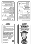
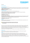
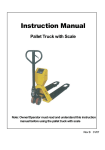
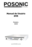
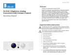
PS-6609 Outdoor Triple Technology Microwave/PIR Motion Detector
Installation Manual
INTRODUCTION
Fig-1 Exploded
View
The 6609 (MW/PIR) is state-of-the-art, microcomputer
controlled triplex technology outdoor intrusion detectors, for
industrial, commercial and residential security. It uses double
PIR and MW technologies, when combined in a single
detector, complement each other to assure the most reliable
detection and immunity to false alarms. The superiority of the
6609 series over other triplex detectors has been achieved by
the advent of the True Motion Detection Technology
algorithm. This advanced motion analysis method provides
the 6609 with the ability to distinguish between the true
motion of a human body and any other disturbances which
invariably cause false alarms.
FEATURES
•
(9) DIP Switch
4-dimensional, all-in-one motion detector.
(10) MW Sensitivity
Adjustment
Two PIR sensors with opposite direction. 40 kg Pet
Immunity
(4)Red LED
•
Auto Background analyse
•
Selectable PIR detection sensitivity. Selectable Microwave
detection sensitivity.
•
Selectable detection technology combination.
•
•
Memory latched input.
Auto temperature compensation.
False alarm prevention of wind immunity and waving
leafs immunity
Multi-directional mounting bracket PS-BK5
•
(3) PCB Module Screw
(11)
Filters
d
(12)Yellow LED
(5) Anti-Tamper
Switch
6)Termi
nal
Block
(7) Back
Fig-2 Back
(8) Screw for
Back
INSTALLATION
1. Location
Installation locations should be carefully selected to avoid proximity to any of the following:
Sun shone directly, rain dipped, reflective surfaces, sources of steam/oil vapor, objects causing temperature
changes such as heaters, and ovens, and infrared light sources.
Large reflecting objects (especially metals) within the coverage area can distort the microwave detector's coverage
pattern. Always mount the unit on a firm and stable surface at a height that renders optimum coverage of the
protected area.
2. Mounting
Select the detector installation site, based on the required coverage and recommended height of 1.8m to 2.4m. The
detector comes equipped with the Posonic "no dead zone" pet immunity lens.
The unit can be installed directly on the wall using the mounting knockouts. Optional swivel brackets permit greater
flexibility when adjusting the coverage area.
After selecting the detector's location, drill holes for the screws as per figure 2. Holes А, В, C and D are to be used
for corner mounts. For a corner mount, the PCB can be carefully removed by loosening the PCB screw. In the case
of flat surface installation, utilize holes M and N. Run the wires through entry holes L and connect them according to
the marking on the PCB or FTG-3.
1
For swivel bracket mounting, utilizes hole E, F, G, H, J and K to fix to the bracket. The angle of bracket can be adjusted down
0-30º and left/right 0-90º in order to get a good coverage area.
3. Wiring
N.O. and C
EOL
MEM
TAMP
Fig-3
Terrminal Block Wiring
12 345 67
Ø Ø
+ -
12V DC
Ø Ø Ø
С N.C NO.
Ø Ø
EOL
N.C. and C
Connect to a power source within the range of
9 to 16 VDC. Take care not to reverse the
polarity.
Normal Closed Alarm Output, Connect to
normally closed burglar protection zones of the
control panel.
Normal Opened Alarm Output, Connect to
normally opened burglar protection zones of
the control panel.
Terminal for connection of a EOL resistor.
Alarm Memory Control, this point receives
signal from the panel. If 0V is received, the
detector will understand that the system is
armed. If 12V or no voltage is received, the
detector will understand that the system is
disarmed.
Tamper Switch output, Connect to a normally
closed 24-hour tamper zone of the control
panel.
MEM
12 V(+) and(-)
89
Ø Ø
TAMP
4. Alarm Memory
Using the programmable output of the control panel to generate ( -12V) to the terminal "MEM" of 6609 upon arming will trigger
the alarm memory function of 6609. If the detector is alarmed during armed period, the alarm signal will be memorized and the
LED will lights for 30 minutes when the panel is disarmed ( delete -12V).
5. Coverage and Adjustment
At the recommended installation height of 1.8m (5.8 ft) to 2.4m ( 7.8 ft), from
1.2m (4 ft) to 12m (39 ft), without any dead zones.
the PS-6609 will provide full coverage
Your unit is equipped with "automatic temperature compensation", which adjusts amplifier gain to maintain coverage levels
across a wide range of temperatures.
Any mounting height should be followed by a walk-test of tne~ protected area. Walk-testing verifies that the required coverage
is in place. With the Posonic standard lens, there should be no dead zones in tne protected area. When walk-testing, always
move across the path of detection, not toward the detector.
6. Power on
After connecting the power source, the 6609 starts a 90-seconds warm-up period, indicated by alternate flashing of both red
and green LEDs. If the alternate flashing of the LEDs do not stop within 90 seconds, a failure has been detected by the selftest circuit. Then the Green LEDs blink rapidly indicating that the detector is starting the background analysis. Once the
analysis completed, the Green LbDs blink again for 5 seconds. The detector is ready to work now.
INDICATION AND SETTING
1. LED Indications
The three LEDs (Fig. 1) are used to signal various alarm and trouble messages as shown in Table 1 below:
Table 1. LED Indications
Status of LEDs
YELLOW RED
Off
Off
On
Off
Off
On
Flashes
Flashes
Meaning
No detection
MW is triggered
PIR is triggered
Alarmed
Notes: 1. During walk testing, normally the first LED to illuminate is the yellow one (MW detection), depending on which one of
the two kinds of sensors (MW and PIR) discovered the motion first. Upon subsequent discovery of the motion by the
PIR sensor, the yellow and red LED will flash (alarm).
2. If the yellow or red LEDs do not illuminate during walk test, a malfunction has been diagnosed. Replace the unit
without delay.
2. Mode Setting
The mode setting DIP Switch is mounted on the detector's PCB board (see Fig. 1). It controls four functions as demonstrated
in Fig. 6 and as detailed in Table 2.
Table 2. Mode Setting DIP Switch
Switch Setting Function
SW-1
ON
All LEDs are enable
OFF
All LEDs are disable
SW-2
ON
PIR sensitivity is high
OFF
PIR sensitivity is low
SW-3
Spare
SW-4
ON
Only Microwave
OFF
Microwave and PIR
Fig-4
DIP Switch Mode Selector
Default Setting
ON
ON
OFF
OFF
LED On/off
PIR Sensitivity
Spare
ADJUSTMENT AND TEST
1. Setting the PIR Pulse Count
If you wish to set the PIR detector for maximum false alarm immunity, shift DIP switch 2 (SW-2) to OFF. In this position,
two consecutive motion pulses are required to trigger the PIR detection. For faster catch performance, shift SW-2 to ON.
In this position, only one motion pulse is required to trigger the PIR detection.
2. PIR Walk Test
A. Rotate the MW sensitivity adjust all the way towards minimum (turn the
adjust anti-clockwise).
B. Verify that DIP switch SW-1 is set to ON (the red walk-test LED is
enabled).
C. Mount the front cover in place.
D. Walk into the detector's field of view at the expected far edge of the coverage area. The red LED should
illuminate for up to 3 seconds each time your motion is
detected.
3. MW Walk Test
A. Remove the front cover.
B. Verify that the MW sensitivity adjust is set to minimum (turn the adjust antiFig-5
clockwise) and DIP switch SW-1 is set to ON (the walk-test LED is
Microwave Sensitiv
enabled).
C. Start by moving into the coverage area at the far edge. The
LED should light steadily for up to 3 seconds each time
your motion is detected.
D. IT your motion was not detected at the far edge of the coverage
area, advance the MW adjust slightly toward
maximum(clockwise) and try again until your motion is
detected reliably at the far edge. The sensitivity can be
adjusted between 25% to 100% (6-24m)
Caution! The MW detection range must not exceed the far
edge of the desired coverage area, otherwise it will detect
movement from outside the walls of the protected area and
causes false alarm.
E. Walk across the coverage area at various ranges and verify
that your motion is consistently detected.
Note: If PIR trips interfere with your test, disable the PIR by inserting a small
piece of cardboard in front of the sensor.
ity
yellow
4 Alarm Walk Test
A. Set DIP switches SW-1 to ON (all LEDs are enabled).
B. Install the front cover in place.
C. Walk across the detector's field of view in different directions, at various distances from the detector, and
verify proper detection throughout the detector's coverage area (the yellow and red LED will flash for 3
seconds).
D. When done, remove the cover and set DIP switch SW-1 OFF to prevent unauthorized people from tracing
the coverage pattern.
E. Remount the cover and fasten it to the base using a screw at the bottom.
3
PET IMMUNITY
The 6609 has two dual opposite element sensors for of 3-D space detection. In addition it combines with the proprietary Petfriendly lens greatly decrease false alarms created by pets. In order to generate an alarm, an object must cross the beams
created by both the lower and upper sensor.
Due to the small height and volume of a pet, they will not generate the required signal value normally recognized as an alarm
situation. Any PCB adjustments should be followed by a walk-test of the protected area. Walk-testing verifies that the required
coverage is in place.
WARRANTY
The Seller warrants its products to be free from defects in materials and workmanship under normal use for a period of one
year. Except as specifically stated herein, all express or implied warranties whatsoever, statutory or otherwise, including
without limitation, any implied warranty of merchantability and fitness for a particular purpose, are expressly excluded. Since
the Seller does not install or connect the products and because the products may be used in conjunction with products not
manufactured by Seller. Seller cannot guarantee the performance of the security system. Seller obligation and liability under
this warranty is expressly limited to repairing or replacing, at Seller's option, any product not meeting the specifications. In no
event shall the Seller be liable to the buyer or any other person for any loss or damages whether direct or indirect or
consequential or incidental, including without limitation, any damages for lost profits stolen goods, or claims by any other
party, caused by defective goods or otherwise arising from the improper, incorrect or otherwise faulty installation or use of the
merchandise sold.
Infrared and Microwave Detection
Top View
Microwave
Detection Area
12m
SPECIFICATIONS
PIR Sensors
PIR Trigger Indication
Pulse Count
Lens
Coverage
Microwave Oscillator
Microwave Frequency
Microwave Range
ivivv i rigger indication Alarm
Indication
Alarm Output
Alarm Duration
Tamper Switch
RFI Protection
White Light Protection
Pet Immunity
Power Source
Operating Current
Mounting
Waterproof Rating
Operating Temperature
Dimensions (H x W x D)
Net Weight
Two Low noise dual-element pyroelectric sensor
Red LED illuminates for up to 3 seconds
Selectable, 1 or 2 pulse count
34 beams, 110° field of view
12m x 110°
DRO-stabilized type
10.525 GHz
Adjustable from 25% to 100% (6 m to 24 m)
YG low LED illuminates for up to 3 seconds
Red and Yellow LEDs flashes for 2-3 seconds
Normally closed and normal opened, 0.1 A
resistive / 30 VDC; 30ohms resistor in series with
contacts
3 seconds (red and yellow LED flash and output
relay contacts trigger)
N.C, 50 mA resistive /30 VDC
>30 V/m (20 MHz to 1000 MHz)
50,000 lux
40 kg
9 to 16 VDC
About 40 m A @ 12 VDC
Surface or corner (without brackets), from 1.8 m
to 2.4m high
IP65
-10°C to 50°C
168 x 9 5 x 6 5 mm
203g
Microwave
Detection
Area
1.5m
1.2m 4m
7m
Area