1
EM DGES—Digital Monitoring
System
Read carefully before using
Manual
http://www.dragon-guard.com
1
Instruction of DGES Digital Monitoring
System
A. Using and principle of DGES system
This anti-thief system is composed mainly by detecting doors and monitor host
and EM deactivator/reactivator and EM strip check equipment and degaussing board
and tags and detachers and EM strips and so on.
1. Detecting doors: 2 or 3 or more detecting doors compose the single channel or
multiple channels at the gate with transmitting and receiving coils inside the doors.
2. Monitor host: connected with detecting doors by special leads. When the
commodities with EM strips inside go into the channel, the normal electromagnetic
shape will change, when the host finds that, the system will alarm immediately.
3. EM deactivator/reactivator: cashiers should degauss the commodities by EM
deactivator/reactivator or degaussing board after the payment. It is usually put beside
the cashier counters for convenient use.
4. EM strips: there are two kinds of EM strips: permanent strips and composite
strips. You could choose one type according to your requirements. Permanent strips
could be magnetized or degaussed by EM deactivator/reactivator. Permanent strips do
not have this function.
5. EM strip check equipment: it is used to checking if there is an EM strip inside
the book.
B. Graphic appearance
http://www.dragon-guard.com
2
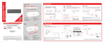
1. Host back panel picture and function introduction .
1). 220V AC outlet with spare fuses inside.
2). Power switch. Make it be ON, host works; make it be OFF, host stops working.
3).4).5). Online interfaces.
6). Input interface of transmitting antenna. Three-chip air plug or five-chip air plug.
7). Input interface 1 of receiving antenna. Four-chip air plug.
8). Input interface 2 of receiving antenna. Four-chip air plug.
2. Host front panel picture and function introduction
1). This is the LBD indicator to receive signals in channel Ⅰ. When it’s bright, the digital displaying
http://www.dragon-guard.com
3
value is the value of receiving signal in channel Ⅰ.
2). This is the LBD indicator to receive alarm reference value in channel Ⅰ. When it’s bright, the
digital displaying value is the receiving alarm reference value in channel Ⅰ.
3). This is the location LBD indicator in channel Ⅰ. When it’s bright, the digital displaying value is the
location indicating value of channel Ⅰ. This value is the less the better.
4). Insignificance.
5). This is the LBD indicator to receive signals in channel Ⅱ. When it’s bright, the digital displaying
value is the value of receiving signal in channel Ⅱ.
6). This is the LBD indicator to receive alarm reference value in channel Ⅱ. When it’s bright, the
digital displaying value is the receiving alarm reference value in channel Ⅱ.
7). This is the location LBD indicator in channel Ⅱ. When it’s bright, the digital displaying value is the
location indicating value of channel Ⅱ. This value is the less the better.
8). Insignificance.
9). This is a four numeral display.
10). This is a displaying window.
11). This is the LBD indicator to receive alarm of channel Ⅰ. When it’s bright, channel Ⅰ receives
alarms.
12). This is the interference LBD indicator of channel Ⅰ. When it’s bright, the channel Ⅰ is closed off
and the alarms will be invalid.
13). This is the LBD indicator to receive alarm of channel Ⅱ. When it’s bright, channel Ⅱ receives
alarms.
14). This is the interference LBD indicator of channel Ⅱ. When it’s bright, the channel Ⅱ is closed off
and the alarms will be invalid.
15). Select button. Press select button, the red LBDs in the displaying window will be lighted one by
one and the digital display will show the corresponding values with those red LBDs one by one.
16). Increase button. Press select button to make the receiving alarm reference value LBD indicator be
lighted in the displaying window of channel Ⅰ and then press increase button, the displaying value in the
window will be increased and what is being increased is receiving alarm reference of channel Ⅰ. Press
select button to make the receiving alarm reference value LBD indicator be lighted in the displaying window
of channel Ⅱ and then press increase button, the displaying value in the window will be increased and what
http://www.dragon-guard.com
4
is being increased is receiving alarm reference of channel Ⅱ.
17). Reduce button. Press select button to make the receiving alarm reference value LBD indicator be
lighted in the displaying window of channel Ⅰ and then press reduce button, the displaying value in the
window will be reduced and what is being reduced is receiving alarm reference of channel Ⅰ. Press select
button to make the receiving alarm reference value LBD indicator be lighted in the displaying window of
channel Ⅱ and then press reduce button, the displaying value in the window will be reduced and what is
being reduced is receiving alarm reference of channel Ⅱ.
18). Store button. If the receiving alarm reference value has been regulated, press this button to store
present receiving alarm reference value of channel Ⅰ and no matter the system is ON or OFF that value
would be sustained as long as no contact on increase button or reduce button. The channel Ⅱ is in the
same way.
3. System connecting picture
(Picture 3)
http://www.dragon-guard.com
5
4. Regulating picture of detecting doors
(Picture 4)
5. Matching board of transmitting antenna
(Picture 5)
1. Transmitting ports:
http://www.dragon-guard.com
6
F+: transmitting coil “+”, F-: transmitting coil “-”, GND: receiving/transmitting yellow wire (blue wire), f+:
receiving/transmitting red wire (black wire); all those above have been connected very well when they were
in our factory so it’s not necessary for clients to connect them. X1: counter signal yellow wire; +5v: counter
power red wire; GND: counter earth wire; those have been connected very well when they were in our factory.
(Those are only used for the counting function.)
2. Port of light wire: has been connected very well when they were in our factory.
3.4. Connecting ports of light wires and receiving doors: connect any one of the two ports with the light
wire port of the receiving antenna matching board. Users should connect them correspondingly by
themselves.
5. Matching board of receiving antenna
(Picture 6)
1. Receiving ports:
J+: receiving coil “+”, blue wire; J-: receiving coil “-“, black wire; GND: yellow receiving wire; J+: red
receiving wire; 0v: blue light wire; +12v: red light wire; those have been connected very well when they were
http://www.dragon-guard.com
7
in our factory.
2. Receiving interface: the users should connect the interface between the receiving 1 and receiving 2.
(This is only used to double channels system.)
3. Buzzer interface: it has been connected very well when they were in our factory.
4. 5K potentiometer: the alarm sound will be louder if you regulate it clockwise and the alarm sound will
be lower if you regulate it counterclockwise.
5. Counter interface: it’s an interface between the transmitting door and the counter (it is only used for
counting function). The user should connect it very well.
6. The port of counting wires: +5v: red counting wire, X: yellow counting wire; GND: blue counting wire;
they are connected very well when they were in our factory.
C. Setting and regulation of system
1. Set the detecting doors in the same direction according to the serial number on
the motherboard.
2. Connect the leading wires at the bottom of the detecting doors in turns of the
way in picture 3.
3. The power of the host should be earthed very well and should be at least 2m
far away from the detecting doors.
4. There should not be large metal things around the detecting doors in the range
of 80cm.
5. Connect the host with the power and turn on the power (the power is at the
back panel of the mainframe case as in picture 1). Then the window will display red
numbers to show that the power is already on.
6. Left-right or forwards-backwards lightly move the two receiving doors
respectively according to the regulating way in picture 4 to let the two green lights
11.13. be extinguished respectively showed in picture 2. Press select button to let the
first red indicator be lightened at the left Ⅰ of the panel displaying window, then the
display in the panel is the signal value of receiving 1. When the EM strips are passing
the detecting channel 1, if the signal value changes that means the channel 1 works
http://www.dragon-guard.com
8
very well. Press select button then to let the second red indicator in the left of the
displaying window to be lightened, the displaying number in the panel is the reference
value that need setting and the value will be increased if you press the increase button
and the value will be reduced if you press the reduce button. Press the two buttons
continually to achieve the reference value the system needs (we advise you to set the
value 30 higher than the static value which showed when there is no EM strips or
other objects passing the detecting channels). Press store button to store the certain
reference value. (Attention: the users should press the store button after every
regulation or the system will memorize last value.) The data will no be lost if the
power is cut off. Press select button to let the first red indicator be lightened in the
right of panel display window, then the display number in the panel is the signal value
of receiving 2. When there are some strips passing the detecting channel 2, this signal
value will change that means channel 2 works very well. Press select button then to let
the second red indicator be lightened in the right of the display window, then the panel
will show the reference value of channel Ⅱ that need setting. The setting way is the
same with then channel Ⅰ.
7. Hole an EM strip. Let the strip be parallel with the ground and be vertical with
the passing direction. When the strip is passing the channel Ⅰ the alarm indicator on
the receiving 1 will give a light-sound alarm. At the same time, the 11 red light
(picture 2) on the right of the host panel will give a light-sound alarm, the signal value
then must be higher than the setting reference value. When the strip is passing the
channel 2 the alarm light on receiving 2 will give a light-sound alarm which is
different from the channel Ⅰ for easy distinguishing and at the same time, the red
light 13 (picture 3) on the right of the host panel will light.
8. Note the location of the detecting door by pencil and prepare for expansion
screws. Set the detecting doors on the screws. Do not fix the screws and redo the 6~7
steps. Tighten the screws after normal working. The system setting and regulation is
finished.
http://www.dragon-guard.com
9
D. Main technical parameters
Channel width: single channel 700mm~1000mm
double channel 1400mm~2000mm
Detecting height: 160 mm
Power: 220V ± 10%
50Hz
Output power: ≤ 13W
Working environment: -10℃~40℃
Continuous working hours: not less than 24 hours
E. Attention
1. There should not be large metal objects or metal guardrails that may damage
the magnetic field around the detecting doors in the range of 80cm and the books or
other commodities should no be put in the range of 80 cm around the detecting doors.
2. Host should be far away from the detecting doors at least 2m. Computers
should not be next to the detecting doors closely. They had better not be on the same
axis. The detecting doors should be far away from the computers at least 2m.
3. Catch hold of the air plugs instead of pulling the wires overexerted for fear
that the wires will be broken when removing or installing the wires.
4. Do not move the detecting doors with hands usually for fear that the setting
location will be influenced.
5. Do avoid trampling or heavy pressure on the wires directly for fear wires
broken or short circuits.
6. Do not turn on and turn off usually for fear host damage.
7. Do turn off the power when replace the fuse. You had better insert the host
plug into a dependent outlet and do not share the outlet with other equipments. This
outlet should be earthed very well.
8. Setting of detecting doors should avoid the large cement pillars and beams and
other wires.
http://www.dragon-guard.com
10
F. Elimination of faults and interference
Eliminate the faults according to the followed steps when the equipments cannot
work normally. If they still cannot work normally, please contact us.
Common Faults
Reasons and eliminations
Continuous
1. Are there some EM strips or books and other objects that have
misreporting
strips inside around the detecting doors?
2. There are large metals and umbrellas and metal cups and metal
bowls and other metal objects next to them closely.
3. The system signal value is a little higher. The normal value
should be less than 0020. Regulate detecting doors to let the signal
value go back to normal.
4. Setting reference is a little lower which should be 20~30 more
than signal value.
5. There are beams or wires beside the detecting doors or at the
bottom of them.
6. Detecting doors are next to the computer monitors closely.
Do not alarm
1. Setting reference value is too high.
2. Interference indicator was light and the signal value was
negative, regulate the detecting doors.
3. Connecting wires was broken, host signal value showed no
change.
4. EM strips was not magnetized enough or they were broken.
5. Detecting doors are next to the computer monitors closely.
Host does not
work
1. Power outlets contact badly.
2. The fuse is broken, change a new one.
G. Advices for administrators
1. Paste some notifications at the observable places. For example, paste some
http://www.dragon-guard.com
11
slogans at the entries such as “there are anti-thief systems in our shop, please
cooperate with them” and at the exits such as “please go to the counters for payment”.
2. How to avoid disputes when found some suspects? Many domestic and
foreign experiments have proved that anti-thief system could stop about 80%~90%
stealing, but workers and administrators should understand that the function of the
anti-thief system is to alarm thieves psychologically to make them give up stealing
rather than a special tool for catching thieves and at the same time the system could
improve the shopping atmosphere which is different from the old watching way to
offer the best respect to more cultured people, so we should have a faith on “we
would prefer to miss 10 thieves instead of catching a wrong person”. Under the
alarming situation, we should think it’s misreporting first, and let the customers
cooperate to walk back and forth again, if the system doesn’t alarm this time do
apologize to the customers, and if the system still alarms, we should say to the
customers like this: “sir/miss, have you forgotten some procedures? It’s ok, please do
it again”. If he/she has some commodities really without normal checking, deal with it
according to your tradition. Few large metal objects such as porcelain enamels and
umbrellas will cause misreporting if they are too close to the doors. Few cell phones
and cameras and VCD machines could also cause misreporting. So pay attention to
these situations when the system alarms. In rare cases, it’s hard to find some thieves
who can hide commodities so perfect that nobody can find that, we have to let them
go for fear catching wrong persons. In fact this loss can be equalized because we
always have a policy that: the thieves should pay 10 times the price for the
commodities they steal. We should believe that though we have some loss, thieves
obtained some “education” or “alarm” through this system and they may not make
such mistakes again easily, this is a good contribution for society.
3. Assign 1~2 administrators for anti-system specially. We will train them when
setting and regulating the system and they will be responsible for repair reporting with
us later.
http://www.dragon-guard.com
12
H. Using skills of anti-thief system
Many merchants have found and concluded a series of using experience and
skills for anti-system with the expansion of its use. There are some typical situations
for users.
1. To judge if there are some misreporting users could follow the next steps:
1). Your commodities are not degaussed enough.
2). There are some commodities that are in other shops are not degaussed
enough.
3). There are large porcelain cups or bowls.
4). There are iron long umbrellas.
5). There are large metal objects on the backpacks.
2. If the system alarms when some customers are passing the detecting channels
to get in, you could ask them to deposit their bags. If they don’t want to deposit the
bags, pay more attention to them, if everything is fine and the system alarms when
they go out, we could not deal with it.
3. If the system alarms when the customers are passing the channels, you could
let them pass again to make sure about the alarms and at the same time you could
explain that doing this is good for them with the posters in your market to let the
customers receipt this gladly.
4. There will always be some misreport and blind spots in the anti-systems no
matter how advanced they are. So we need a new concept to understand their function
correctly: what we want is a good environment and a minimum loss rate rather than
the number of thieves.
5. We could reduce the strip loss and improve the environment largely by
scientific management.
http://www.dragon-guard.com
13