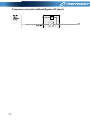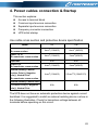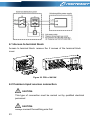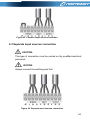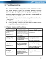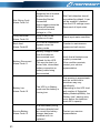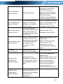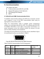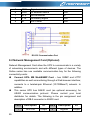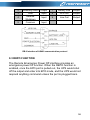
1
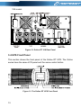
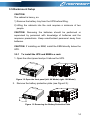
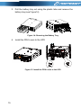
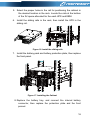
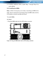
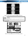
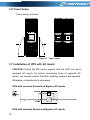
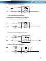
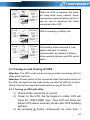
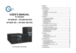
USER MANUAL
On-Line UPS
PowerWalker VFI 6000RT LCD
PowerWalker VFI 10000RT LCD
Uninterruptible Power Supply System
Contents
1. Introduction ............................................................................................. 1
2. Safety Warnings ...................................................................................... 4
2.1 Installation .......................................................................................... 4
2.2 Operation ............................................................................................ 5
2.3 Maintenance, servicing and faults ...................................................... 6
2.4 Transport ............................................................................................ 7
2.5 Storage ............................................................................................... 7
2.6 Standards ........................................................................................... 7
3. Installation ............................................................................................... 9
3.1 Inspecting the Equipment ................................................................... 9
3.2 Unpacking the Cabinet ....................................................................... 9
3.3 UPS Rear Panel ............................................................................... 12
3.4 UPS Front Panel............................................................................... 13
3.5 Rackmount Setup ............................................................................. 14
3.6 Tower Setup ...................................................................................... 19
3.7 Installation of UPS with AC inputs .................................................... 19
4. Power cables connection & Startup ................................................... 22
4.1 Access to terminal block ................................................................... 23
4.2 Common input sources connection .................................................. 23
4.3 Separate input sources connection .................................................. 24
4.4 Frequency converter connection ...................................................... 25
4.5 UPS Initial Startup ............................................................................ 25
4.6 Parallel operation ............................................................................. 26
5. Operation ............................................................................................... 29
5.1 Display Panel.................................................................................... 29
5.2 Operating mode ................................................................................ 31
5.3 Turning on and Turning off UPS ....................................................... 34
5.4 LCD operation .................................................................................. 36
6. UPS Maintenance .................................................................................. 45
6.1 UPS and Battery Care ...................................................................... 45
6.2 Transporting the UPS ....................................................................... 45
6.3 Storing the UPS and Batteries.......................................................... 46
6.4 Testing Batteries ............................................................................... 46
6.5 Recycling the Used Battery or UPS ................................................. 47
7. Specifications........................................................................................ 48
8. Troubleshooting .................................................................................... 50
8.1 Typical Alarms and Conditions ......................................................... 50
9. Communication ..................................................................................... 54
9.1 RS-232 and USB Communication Ports .......................................... 54
9.2 Network Management Card (Optional) ............................................ 55
9.3 UPS Management Software ............................................................. 56
9.4 REPO FUNCTION ............................................................................ 56
1. Introduction
This Online RT (Rack/Tower) Series is an uninterruptible power
supply incorporating double-conversion technology. It provides
perfect protection
specifically for computer equipment,
communication systems to computerized instruments. It protects
your sensitive electronic equipment from basic power problems such
as power failures, power sags, power surges, brownout, and line
noise.
Power outages can occur when you least expect them and power
quality can be erratic. These power problems have the potential to
corrupt critical data, destroy unsaved work sessions, and damage
hardware - causing hours of lost productivity and expensive
repairs.
With the Online RT UPS, you can safely eliminate the effects of
power disturbances and guard the integrity of your equipment. The
UPS’s flexibility to handle an array of network devices makes it the
perfect choice to protect your LANs, servers, workstations, and other
electrical equipment.
Online RT UPS as Rack installation:
Figure1: Online RT 6K UPS
1
Figure2: Online RT 10K UPS
Online RT UPS as Tower installation.
Figure3: Online RT 6K UPS
Figure4: Online RT 10K UPS
2
Providing outstanding performance and reliability, the UPS’s unique
benefits include:
Online UPS design with pure sine wave output.
True online double-conversion technology with high power
density, utility frequency independence, and generator
compatibility.
Intelligent Battery Management technology that uses advanced
battery management to increase battery service life, optimize
recharge time.
Selectable High Efficiency mode of operation.
Start-on-battery capability for powering up the UPS even if
utility power is not available.
Standard communication options: one RS-232 communication
port, one USB communication port.
Optional connectivity cards with enhanced communication
capabilities.
Extended runtime with up to four Extended Battery Modules
(EBMs) per UPS.
Optional installation method - Rack & Tower.
Firmware is easily upgraded without a service call.
Remote shutdown control through the Remote Emergent
Power-off (REPO) port.
Maintenances are simplified by allowing the safe replacement
of batteries without powering down the UPS.
Parallel with another Online RT UPS, max amount is 2.
Optional Rack Slider.
PDU is standard configuration with maintenance bypass
switch.
3
2. Safety Warnings
CAUTION:
Before performing the procedures in this document, read and follow
the safety instructions and important regulatory information in your
Safety, Environmental, and Regulatory Information document.
IMPORTANT SAFETY INSTRUCTIONS FOR EACH STEP SAVE
THESE INSTRRUCTIONS.
2.1 Installation
★ Condensation may occur if the UPS is moved directly from a cold
to a warm environment. The UPS must be absolutely dry before
being installed. Please allow an acclimatization time of at least
two hours.
★ Do not install the UPS near water or in damp environment.
★ Do not install the UPS where it would be exposed to direct
sunlight or near heat.
★ Do not block ventilation openings in the UPS’s housing.
★ Place cables in such a way that no one can step on or trip over
them.
★ UPS has provided earthed terminal, in the final installed system
configuration, equipotent earth bonding to the external UPS
battery cabinets.
★ An integral single emergency switching device which prevents
further supply to the load by the UPS in any operation mode
should be provided in the building wiring installation.
★ An appropriate disconnect device as short-circuit backup
protection should be provided in the building wiring installation.
★ For three-phase equipment connection to an IT power system, a
four-pole device which disconnect all phase conductors and the
4
neutral conductor should be provided in the building wiring
installation.
★ This is permanently connected equipment , it must be installed
by qualified maintenance personnel.
★ For permanently connected equipment: make sure that a
readily accessible disconnect device is incorporated in the
building installation wiring.
To reduce the risk of fire, connect only to a circuit provided with
branch circuit overcurrent protection with an ampere rating in
accordance with the IEC/EN 60934 standard or your local
electrical code and have a contact air gap of at least 3 mm.
Uninterruptible power supply
output power
6K
10K
★
240V
40 amp
2-pole circuit breaker
63 amp
2-pole circuit breaker
You can connect four extended battery module to the
uninterruptible power supply.
★ Earth connection is essential before connecting to the building
wiring terminal.
2.2 Operation
★ Do not disconnect the earth conductor cable from the UPS or the
building wiring terminals in any time since this would cancel the
protective earthing of the UPS system and all connected loads.
★ The UPS output terminal block may be electrically active even if
the UPS system is not connected to the building wiring terminal.
★ In order to completely disconnect the UPS, firstly press the OFF
button, then disconnect the mains lead.
★ Ensure that no liquid or other foreign objects can enter the UPS.
5
★ The UPS can be operated by any individuals without previous
experience.
2.3 Maintenance, servicing and faults
The UPS operates with hazardous voltages. Maintenance
should be carried out only by qualified maintenance personnel.
Caution - risk of electric shock. Even after the unit is
disconnected from the mains power supply (building wiring
terminal), components inside the UPS are still connected to the
battery which are potentially dangerous.
Before carrying out any kind of service and/or maintenance,
please disconnect the batteries. Verify that no current is present
and no hazardous voltage exists in the capacitor or BUS
capacitor terminals.
Batteries must be replaced only by qualified personnel.
Caution - risk of electric shock. The battery circuit is not isolated
from the input voltage. Hazardous voltages may occur between
the battery terminals and the ground. Verify that no voltage is
present before servicing!
Batteries have a high short-circuit current and pose a risk of
shock. Take all precautionary measures specified below and any
other measures necessary when working with batteries:
- remove all jewellery, wristwatches, rings and other metal
objects
- use only tools with insulated grips and handles.
When changing batteries, replace with the same quantity and the
same type of batteries.
Do not attempt to dispose of batteries by burning them. It could
cause explosion.
Do not open or destroy batteries. Effluent electrolyte can cause
injury to the skin and eyes. It may be toxic.
6
Please replace the fuse only with the same type and of the same
amperage in order to avoid fire hazards.
Do not dismantle the UPS, except the qualified maintenance
personnel.
2.4 Transport
Please transport the UPS only in the original packaging (to
protect against shock and impact).
2.5 Storage
The UPS must be stockpiled in the room where is ventilated and
dry.
2.6 Standards
* Safety
IEC/EN 62040-1-1
* EMI
Conducted Emission.........................:IEC/EN 62040-2
Category C2
Radiated Emission............................:IEC/EN 62040-2
Category C2
*EMS
ESD................................................:IEC/EN 61000-4-2
Level 4
RS..................................................:IEC/EN 61000-4-3
Level 3
EFT................................................ :IEC/EN 61000-4-4
Level 4
SURGE......................................... :IEC/EN 61000-4-5
Level 4
CS................................................. :IEC/EN 61000-4-6
Level 3
Power-frequency Magnetic field.... :IEC/EN 61000-4-8
Level 3
7
Low Frequency Signals..................:IEC/EN 61000-2-2
Warning: This is a product for commercial and industrial application
in the second environment-installation restrictions or additional
measures may be needed to prevent disturbances.
8
3. Installation
This chapter explains:
Equipment inspection
Unpacking the cabinet
Checking the Accessory
UPS setup and installation
Connecting the internal battery
Connecting the EBM(s)
Installation requirements
3.1 Inspecting the Equipment
If any equipment has been damaged during shipment, keep the
shipping cartons and packing materials for the carrier or place of
purchase and file a claim for shipping damage. If you discover
damage after acceptance, file a claim for concealed damage.
Note: Check the battery recharge date on the shipping carton label.
If the date has passed and the batteries were never recharged, do
not use the UPS. Contact your service representative.
3.2 Unpacking the Cabinet
CAUTION: Unpacking the cabinet in a low-temperature environment
may cause condensation to occur in and on the cabinet. Do not
install the cabinet until the inside and outside of the cabinet are
absolutely dry (hazard of electric shock).
CAUTION: The cabinet is heavy. Use caution to unpack and move
the cabinet.
Be careful when moving and opening the carton. Leave the
components packaged until ready to install. To unpack the system:
9
Step 1:
Open the outer carton and remove the accessories packaged with
the cabinet (see Figure 5&6).
Online RT 6KUPS:
Figure5: Unpacking the Cabinet of 6K UPS
Online RT 10K UPS
Figure6: Unpacking the Cabinet of 10K UPS
10
CAUTION:
The cabinet is heavy. Lifting the cabinets into the rack requires a
minimum of two people.
Step 2:
With one person on each side, carefully lift the cabinet out of the
outer carton using the handles on the cardboard and set it on a flat,
stable surface (see Figure 7&8).
Place the cabinet in a protected area that has adequate airflow and
is free of humidity, flammable gas, and corrosion.
Lifting the Cabinet:
Figure7: Lifting the Cabinet of 6K UPS
11
Figure8: Lifting the Cabinet of 10K UPS
Step 3:
Discard or recycle the packaging in a responsible manner, or store
it for future use.
3.3 UPS Rear Panel
This section shows the rear panel of the Online RT models.
6K model:
Figure 9: Online RT 6K Rear Panel
12
10K model:
Figure 10: Online RT 10K Rear Panel
3.4 UPS Front Panel
This section shows the front panel of the Online RT UPS. The Online
series have the same LCD panel and the same control button.
Figure 11: The Online RT UPS Front Panel
13
3.5 Rackmount Setup
CAUTION:
The cabinet is heavy, so:
1) Remove the battery tray from the UPS before lifting.
2) Lifting the cabinets into the rack requires a minimum of two
people.
CAUTION: Removing the batteries should be performed or
supervised by personnel with knowledge of batteries and the
requieres precautions. Keep unauthorized personnel away from
batteries.
CAUTION: If installing an EBM, install the EBM directly below the
UPS.
3.5.1 To install the UPS and EBM in a rack:
1. Open the sfront panel and put it above the UPS.
Figure 12. Open the front panel (left: 6K Model, right: 10K Model)
2. Remove the battery protection plate (see Figure13):
Figure 13. Removing the Battery Protection Plate
14
3. Pull the battery tray out using the plastic tabs and remove the
battery tray.(see Figure14)
Figure 14: Removing the Battery Tray
4. Install the PDU’s ears to the UPS
Figure 15. Install the PDU’s ears to the UPS
15
5. Select the proper holes in the rail for positioning the cabinet in
the desired location in the rack. Locate the rails at the bottom
of the 3U space allocated for the each UPS and EBM.
6. Install the sliding rails in the rack, then install the UPS in the
sliding rail.
Figure 16. Install the sliding rails
7. Install the battery pack and battery protection plate, then replace
the front panel.
Figure 17. Installing the Cabinet
8. Replace the battery tray, and connect the internal battery
connector, then replace the protection plate and the front
pannel.
16
9. If installing additional UPSs, repeat Step 1 through Step 8 for
each cabinet.
3.5.2 Installing the EBMs
Note: A little of arcing may occur when connecting an EBM to the
UPS. This is normal and not harmed. Plug the EBM cable into the
UPS battery connector quickliy and firmly.
To install EBMs:
6K Model:
1. Plug the EBM cable into the UPS battery connctor
Figure 18. Plug the EBM cable into the UPS battery connctor
17
2. Replace UPS’s front pannel and EBM’s front pannel.
Figure 19. Replace UPS’s front pannel and EBM’s front pannel.
CAUTION:
Please connect the EBM to protective ground with 8 AWG wire for
EBM model firstly.
10K Model:
Figure 20. Plug the EBM cable into the UPS battery conector
18
3.6 Tower Setup
Tower setup as below:
Figure 21. Tower setup
3.7 Installation of UPS with AC inputs
CAUTION: Online 6K/10K series support that the UPS can have
separate AC inputs. So before connecting wires of seperate AC
inputs, you should confirm that their earthing systems are identical.
Otherwise, a transformer is necessary.
UPS with common Normal and Bypass AC inputs
UPS with separate Normal and Bypass AC inputs
19
Earthing systems are identical:
Earthing systems are separate:
Three different installations can be choosen:
1) Transformer in the Normal AC input.
2) Transformer in the Bypass AC input.
3) Both of them have transformer
20
Frequency converter (without Bypass AC input)
21
4. Power cables connection & Startup
This section explains:
Access to terminal block
Common input sources connection
Separate input sources connection
Frequency converter connection
UPS initial startup
Use cable cross section and protective device specification
Model
6K
10K
Protective earthing conductor
Min cross section
4mm (10AWG)
2
6mm (8AWG)
Input L, N, G
Min conductor cross section
4mm (10AWG)
2
6mm (8AWG)
60A
80A
Input fuse
Output L,N,
Min conductor cross section
4mm (10AWG)
External Battery Cabinet
Positive Pole(+), Negative
pole(-), Neutral Pole
Min conductor cross section
2
2
2
6mm (8AWG)
2
4mm (10AWG)
2
2.5mm *2 (12AWG*2)
60A
80A
2
External Battery Cabinet Fuse
in Positive Pole(+), Negative
pole(-), Neutral Pole
The UPS does not have an automatic protection device against current
backfeed. It is suggested to install an external isolating device a show in
the following illustration. Check for hazardous voltage between all
terminals before operating on this circuit.
22
4.1 Access to terminal block
Access to terminal block: remove the 2 screws of the terminal block
cover
Figure 22. PDU of 6K/10K
4.2 Common input sources connection
CAUTION:
This type of connection must be carried out by qualified electrical
personnel
CAUTION:
Always connect the earthing wire first
23
Figure 23. Common input sources conection
4.3 Separate input sources connection
CAUTION:
This type of connection must be carried out by qualified electrical
personnel.
CAUTION:
Always connect the earthing wire first.
Figure 24. Separate input sources connection
24
4.4 Frequency converter connection
Figure 25. Frequency converter connection
4.5 UPS Initial Startup
To start up the UPS:
Verify that the total equipment ratings do not exceed the UPS
capacity to prevent an overload alarm.
1. Verify that the internal batterties are connected.
2. If optional EBMs are installed, verify that the EBMs are
connected to the UPS.
3. Set the upstream circuit breaker (not included) to the “I” position
(ON).
The UPS display panel illuminates and shows a status of
“Welcome”
4. Verify that the UPS transfers to Bypass mode.
5. Press the
seconds.
button on the UPS front panel for at least three
The UPS display “
” with flashing.
6. Check the UPS display for active alarms or notices. Resolve any
active alarms before continuing. See “Troubleshooting”
25
7. Verify that the UPS is operating normally and any loads are
powered.
8. If optional EBMs are installed, see “Configuring the UPS for
EBMs” to set the number of installed EBMs.
9. To change any other factory-set defaults, see “Operation”
Online series recommends setting the date and time.
At initial startup, the UPS sets system frequency according to
input line frequency (input frequency auto-sensing is enabled by
default). After initial startup, auto-sensing is disabled until
manually re-enabled by output frequency setting.
At initial startup, inut voltage auto-sensing is disbaled by default.
When manually enabled by output voltage setting, at the next AC
startup the UPS sets output voltage according to input line
voltage. After the subsequent startup, auto-sensing is disabled
until manually re-enabled by output voltage setting.
10. If you installed an optional REPO, test the REPO function:
Activate the external REPO switch. Verify the status change on
the UPS display.
Deactivate the external REPO switch and restart the UPS.
4.6 Parallel operation
4.6.1 Brief introduction of the redundancy
The parallel structure is 1+1.As long as the UPS is equipped with
parallel cables, up to 2 UPSs can be connected in parallel to
configure a sharing and redundant output power.
4.6.2 Parallel installation
1)
Users need to use a specialty 15-pin communication cable for
this series, which should have 15 cores, corresponding stitches
and shield, as the UPS parallel cable. The length of the parallel
cable is appropriate to be less than 3 m.
2)
Strictly follow the stand-alone wiring requirement to perform the
input wiring of each UPS.
26
3)
Connect the output wires of each UPS to an output breaker
panel.
4)
Connect each output breaker to a main output breaker and
then to the loads.
5)
Each UPS need an independent battery bank.
6)
Please refer to the wiring diagram in the next page, and select
suitable breaker.
■ The output wiring requirement is as follows:
●
When the distance among the UPSs in parallel and the breaker
panel is less than 10 meters, the length difference between
input and output cable of the UPSs is required to be less than
20%.
●
When the distance among the UPSs in parallel and the breaker
panel is farther than 20 meters, the length difference between
input and output cable of the UPSs is required to be less than
5%.
4.6.3 Operation and maintenance
1)
For normal operating, follow the single operating requirement.
2) Startup: The units transfer to INV mode simultaneously as they
start up sequentially in Line mode.
3) Shutdown: the units are shut down on INV mode in a sequent
way. When the last one completes the shutdown action, each
unit will turn off the inverter simultaneously and transfer to
Bypass mode.
27
Figure 26. Parallel systerm wiring diagram of 6K/10K
28
5. Operation
5.1 Display Panel
The UPS has a four-button graphical LCD with dual color backlight.
Standard back-light is used to light up the display with white text and
a blue background. When the UPS has a critical alarm, the backlight
changes the text to dark amber and the background to red. See
Figure below
Figure5-1. Innova 6-10K Rack On-line UPS Control Panel
Table 5-1 Control Button Functions
The Button
29
Funtion
Illustration
Power on
When the unit is no power and has
connected with battery, press this button
for >100ms&<1s to power on
Turn on
When the unit is powered on and in
Bypass mode, press this button for >1s
to turn on
Turn off
When the unit has been turned on,
press this button for >3s to turn off
Enter main
menu
Exit main
menu
Scroll up
Scroll down
Enter next
menu tree
Select one
menu
option
Confirm the
present
setting
When displaying default UPS status
summary screen, press this button
for >1s to enter the main menu tree
Press this button for >1s to exit the
present menu to default system status
display menu without executing a
command or changing a setting
Press this button for >100ms&<1s to
scroll up the menu option
Press this button for >100ms&<1s to
scroll down the menu option
Press this button for >100ms&<1s to
select the present menu option, or enter
next menu, but do not change any
setting
Press this button for >100ms&<1s to
select the present menu option, or enter
next menu, but do not change any
setting
Press this button for >1s to confirm the
edited options and change the setting
Table 5-2 Buzzer definition
UPS condition
Fault active
Warning active
Battery output
Bypass output
Buzzer status
Continuous
Beep every second
Beep every 4 seconds, if battery low, buzzer Beep
every second
Beep every 2 minutes
The UPS provides useful information about UPS itself, load status,
events, measurements, identification, and settings through the front
panel display.
30
After powering on, the LCD will display Welcome logo for several
seconds and then enter to the default page which shows the UPS status
summary. The display automatically returns to the default UPS status
summary screen when no button has been pressed within 15 minutes.
On the UPS status summary screen it provides the following information:
Status summary, including mode and load
Alarm status, if any are present
Notes: alarm including fault and warning information
Battery and charger status, including battery voltage, charge level
and charger status
Running information and running time
Fig. 5-2 The default LCD display
The more detailed operation of LCD is illustrated in the chapter of 5.4
5.2 Operating mode
The different graphic symbol could be displayed corresponding to
current operating mode or status.
31
Table 5-3 Status Summary Screens
Status Summary Screen
Description
Normal mode:
The UPS is operating in Normal mode
from utility power.
Fig 5-3
Battery mode:
When the UPS is running in battery
mode, the buzzer beeps once every 4
seconds.
Fig 5-4
Bypass with output:
Fig 5-5
The UPS does not have the backup
function when it is in bypass mode.
The power used by the load is supplied
from the utility power via internal filter.
The UPS will beep once every 2
minutes in bypass mode.
Bypass without output:
The UPS in bypass mode without
output
Fig 5-6
Fig 5-7
High Efficiency Mode:
After the UPS is turned on, the power
used by the load is supplied from the
utility power via internal filter while the
utility power is in normal range, so the
high efficiency could be gained in the
HE mode. Once the mains is loss or
abnormal, the UPS would transfer to
Line mode or Battery mode and the
load is supplied continuously.
1) The function could be enabled
32
Fig 5-8
through the LCD setting or the
software (Winpower, etc.).
2) It is attention that the transfer time
of UPS output from HE mode to
battery mode is about 10ms. But it
is still too long for some sensitive
load.
Converter mode
In converter mode, the UPS would free
run with fixed output frequency (50Hz
or 60Hz). Once the mains is loss or
abnormal, the UPS would transfer to
battery mode and the load is supplied
continuously.
1) The function could be enabled
through the LCD setting or the
software (Winpower, etc.).
2) The load should be derating to
70% in converter mode.
Warning:
Fig 5-9
When the warning occurs, it illustrates
that there are some abnormal
problems during the operation of UPS.
Normally the problems are not fatal
and the UPS continues working, but
they should be paid attention to, or the
UPS may fail.
Fault:
Fig 5-10
33
When the fault occurs, it illustrates that
some fatal problems happened, the
UPS would directly cut off the output or
transfer to bypass, and keep alarming.
The backlight of LCD would also turn
to red.
Overload:
Fig 5-11
When the UPS is overload, the alarm
will beep twice every second. Some
unnecessary loads should be get rid of
one by one to decrease the loads
connected to the UPS.
Battery Test
UPS is executing a battery test
Fig 5-12
Battery fail:
Fig 5-13
if the battery status detected is “bad
battery detected” or “battery
disconnected”, the symbol of battery
failure would be shown and UPS would
alarm.
5.3 Turning on and Turning off UPS
Attention: The UPS could only be turning on while connecting with the
utility at the first time.
Attention: Please switch off the connected loads first before turning on
the UPS, and switch on the loads one by one after the UPS is turned on.
Switch off all of the connected loads before turning off the UPS.
5.3.1 Turning on UPS with utility
1) Check all the connection is correct.
2) Power on the UPS, the fan begins to rotate, LCD will
show the “WELCOME” logo. Then LCD will show the
default UPS status summary screen after UPS finishing
self-test.
3) By pressing
button continuously for more than 1
34
second, the buzzer will beep 1s, UPS starts to turn on.
4) A few seconds later, the UPS turns into Line mode. If
the utility power is abnormal, the UPS will transfer to
Battery mode without output interruption of the UPS.
5.3.2 Turning on UPS without utility
1) Check all the connection is correct.
2) By pressing
button continuously for more than
100ms, the UPS would be powered on. At this time the
fan begins to rotate, LCD will show the “WELCOME”
logo. Then LCD will show the default UPS status
summary screen after UPS finishing self-test.
3) By pressing
button continuously for more than 1
second, the buzzer will beep 1s, UPS starts to turn on.
4) A few seconds later, the UPS turns into Battery mode. If
the utility power comes back, the UPS will transfer to
Line mode without output interruption of the UPS.
5.3.3 Turning off UPS with utility
1) To turn off the inverter of UPS by pressing
button
continuously for more than 3 seconds and the buzzer
will beep 3s. The UPS will turn into Bypass mode at
once.
2) When completing the above action, UPS output voltage
is still present. In order to cut off the UPS output, simply
cut off the utility power supply. A few seconds later, LCD
display shuts down and no output voltage is available
from the UPS output terminal.
5.3.4 Turning off UPS without utility
1) To power off the UPS by pressing
button
continuously for more than 3 second, and the buzzer
will beep 3s. The UPS will cut off the output at once.
35
2) A few seconds later, LCD shuts down and no voltage is
available from the UPS output.
5.4 LCD operation
Except the default UPS status summary screen, the user
could get more useful information about UPS current
status, detailed various measurements, old events which
ever occurred, UPS own identification, and could change
the settings to fit the user own requirements, optimize the
function of UPS.
5.4.1 The main menu
In the default UPS status summary screen, when pressing
or
<1s, the detailed information about alarm, the
system status, battery would be shown.
In the default UPS status summary screen, when pressing
>1s, the display would enter main menu tree.
The main menu tree includes six branches: UPS status
menu, event log menu, measurement menu, control menu,
identification menu, setting menu.
36
Fig. 5-14 Main menu tree
37
5.4.2 The UPS status menu
By pressing
on the menu of “UPS status”, the display
would enter the next UPS status menu tree.
The content of UPS status menu tree is same as the
default UPS status summary menu.
By pressing
>1s, the display would return the last main
menu tree.
The detail information about “UPS status”, please see
Fig5-14
5.4.3 The event log menu
By pressing
on the menu of “Event log”, the display
would enter the next event menu tree.
All the old event, alarm and fault have been recorded here.
The information includes the illustration, the event code,
and the operating time of UPS when the event happened.
By press
or
<1s, all the event could be displayed
one by one.
The max number of record is 50, when the number is
larger than 50, the oldest one would be changed to the
newest information.
>1s, the display would return the last main
By pressing
menu tree.
38
Fig. 5-15 Event menu tree
5.4.4 The measurement menu
By pressing
on the menu of “Measurement”, the
display would enter the next measurement menu tree.
A lot of detailed useful information could be checked here,
Ex. the output voltage and frequency, the output current,
the load capacity, the input voltage and frequency, etc.
By pressing
>1s, the display would return the last main
menu tree.
39
Fig. 5-16 Measurement menu tree
5.4.5 The control menu
By pressing
on the menu of “Control”, the display
would enter the next control menu tree.
1) Start Battery Test: is one command to control the UPS
to do the battery test.
2) Clear EPO status: once EPO status is enabled, the
UPS output would be cut off. To recover to normal
status, first EPO connector should be closed, and enter
this menu to clear EPO status, then UPS would stop
alarm and recover to Bypass model. And UPS needs
be turned on by manual operation.
3) Reset Fault status: when fault occurs, UPS would keep
in Fault mode and alarm. To recover to normal status,
40
enter this menu to reset error status, then UPS would
stop alarm and recover to Bypass mode. And the
reason of fault should be checked and deleted before
UPS is turned on again by manual operation.
4) Restore factory settings: all the settings would be
recover to default factory settings. It could only be done
in Bypass mode.
Fig. 5-17 Control menu tree
41
5.4.6 The identification menu
By press
on the menu of “Identification”, the display
would enter the next identification menu tree.
The identification information includes UPS serial number,
firmware serial number, model type, would be shown here.
By press
>1s, the display would return the last main
menu tree.
Fig. 5-18 Identification menu tree
5.4.7 The setting menu
Please contact your local distributor for further information
before using the settings. Some settings would change the
specification, and some settings would enable or disable
some functions. The unsuitable option set by user may
42
result in potential failures or protecting function loss, even
directly damage the load, battery or UPS.
The most of settings could only be done while UPS is in
Bypass mode.
Fig. 5-19 Setting menu tree
43
Example: set rated output voltage value
Fig. 5-22 Set rated output voltage value
44
6. UPS Maintenance
This chapter explains how to:
Care for the UPS and batteries
Transport the UPS
Store the UPS and batteries
Test the batteries
Recycle the used Battery or UPS
6.1 UPS and Battery Care
For the best preventive maintenance, keep the area around the UPS
clean and dust-free. If the atmosphere is very dusty, clean the outside of
the system with a vacuum cleaner. For full battery life, keep the UPS at
an ambient temperature of 25°C (77°F)
Note: The batteries in the UPS are rated for a 3-5 year service life. The
length of service life varies, depending on the frequency of usage and
ambient temperature. Batteries used beyond expected service life will
often have severely reduced runtimes. Replace batteries at least every 5
years to keep units running at peak efficiency.
6.2 Transporting the UPS
NOTE: The internal UPS batteries MUST be disconnected before
transport.
CAUTION: The following procedure should be performed or supervised
by personnel knowledgeable about batteries and the required prec
aution. Keep unauthorized personnel away from batteries.
If the UPS requires any type of transportation, the batteries must be
disconnected (but not removed) before the unit is transported:
1. Verify that the UPS is off and disconnected from utility power.
2. Place the UPS on a flat, stable surface with the front of the cabinet
facing you.
3. Remove the UPS front cover
45
4. Disconnect the internal battery connectors
5. Replace the UPS front cover
6.3 Storing the UPS and Batteries
If you store the UPS for a long period, recharge the battery every 6
months by connecting the UPS to utility power. The batteries charge to
90% capacity in approximately 4 hours. However, it is recommended
that the batteries charge for 48 hours after long-term storage.
Check the battery recharge date on the shipping carton label. If the date
has passed and the batteries were never recharged, do not use the UPS.
Contact your service representative.
When to Replace Batteries
When the status summary screen displays the UPS fault icon with the
“Service Battery” alarm and the audible alarm sounds continuously, the
batteries may need replacing. Contact your service representative to
order new batteries.
6.4 Testing Batteries
For a battery test, please check:
The batteries must be fully charged.
The UPS must be in Normal mode with no active alarms.
The load must be higher than 10%.
To test batteries:
1
Connect the UPS to utility power for at least 48 hours to charge
the batteries.
2
Press the
button for one second to go to the main menu
selection and scroll down to the Control menu using the
button.
3
Press the
4
Use the
5
Press the
button to enter the Control menu.
button to scroll to the Battery Test option.
button to start the battery test.
46
During the battery test, the UPS transfers to Battery mode and
discharges the batteries for 25% of the original expected runtime.
The status screen displays “Battery test running” and the percentage
of the test completed. The results display on the UPS status screen
as completing.
6.5 Recycling the Used Battery or UPS
Contact your local recycling or hazardous waste center for information
on proper disposal of the used battery or UPS.
47
7. Specifications
This chapter provides the following specifications:
Model list
General Specification
Electrical Performance
Environmental and Safety
Table4. Model list
UPS Model
EBM Model
6K model
180V EBM
10K model
240V EBM
Table5. General specification
Model
Power Rating
Frequency (Hz)
Voltage
Input
Current
Voltage
Battery
Current
Voltage
Current
Dimension
(WxDxH) mm
Weight (kg)
6K
6KVA/5.4KW
50/60
(120-276)VAC
32A max.
180VDC
38A max
208VAC/220VAC/
230VAC/ 240VAC
28A
10K
10KVA/9KW
50/60
(120-276)VAC
55A max.
240VDC
52A max
208VAC/220VAC/
230VAC/ 240VAC
46A
438 x 698 x 129
438 x 704 x 215.5
46 kg
82.5Kg
Table6. Electrical performance
Input
Model
Voltage
Frequency
Power Factor
6K/10K
Single-phase
50/60 Hz±10%
>0.99(@Full load)
48
Output
Voltage
Power
Regulation Factor
±1%
0.9 lag
Frequency
tolerance
Synchronized
50/60Hz±10%
in Line mode
(AC mode)
±0.1% of
normal
frequency in
Battery mode
THD<2%
Full load
(Linear
Load)/
<5% for
reference
non-linear
load
Current
crest ratio
Overload capacity
Distortion
102%-130% load
transfers to Bypass
mode after 2 minutes
>130% load transfers
to Bypass mode after
30 second and
shutdown the output
after 1 minute
3:1
maximum
Table7. Environment and safety
Temperature
Humidity
Altitude
Storage temperature
0°C-40°C
<95%
<1000m
0°C-40°C
Note: if the UPS is installed or used in a place where the altitude is
above than 1000m, the output power must be derated in use, please
refer to the following:
Altitude (M)
Derating
Power
1000
1500
2000
2500
3000
3500
4000
4500
5000
100%
95%
91%
86%
82%
78%
74%
70%
67%
Safety
EMI
EMS
Conducted Emission
IEC/EN 62040-2
Radiated Emission
IEC/EN 62040-2
ESD
IEC/EN 61000-4-2
Level 4
RS
IEC/EN 61000-4-3
Level 3
EFT
IEC/EN 61000-4-4
Level 4
SURGE
IEC/EN 61000-4-5
Level 4
CS
IEC/EN 61000-4-6
Level 3
IEC/EN 61000-4-8
Level 3
Power-frequency Magnetic field
Low Frequency Signals
49
IEC/EN 62040-1-1
IEC/EN 61000-2-2
8. Troubleshooting
The online series UPS is designed for durable, automatic operation
and issues alarms to alert you whenever potential operating
problems occur. Usually the alarms shown by the control panel do
not mean that the output power is affected. Instead, they are
preventive alarms intended to alert the user. Active alarms are
accompanied by an audible buzzer.
The control panel provides troubleshooting information from two
main menus:
UPS status menu: Access to all active alarms
Event Log menu: Access to the most recent 50 events, which
may include active and closed alarms
8.1 Typical Alarms and Conditions
Alarm or Condition
Possible cause
ON Maintenance
Bypass
Alarm Code: 72
UPS was manually
commanded to switch to
bypass and will remain in
bypass until commanded
out of bypass
In Battery Mode
Alarm Code: 62
A utility failure has
occurred and the UPS is
in Battery mode.
In Eco Mode
Alarm Code: 63
The UPS is on bypass
while operating on the
High Efficiency setting.
Epo Active
Alarm Code: 71
The external contacts in
the rear of the UPS are
configured for REPO
operation and they have
been activated.
Action
Check the maintain bypass
switch status
The UPS is powering the
equipment with battery
power. Prepare your
equipment for shutdown.
The equipment transferred to
bypass utility power as a
normal function of High
Efficiency operation. Battery
mode is available and your
equipment is protected.
Check the EPO connector
status
50
51
Site Wiring Fault
Alarm Code: 04
Site Fault detection is
supported on all models
anytime there is a
Grounding Neutral
connection.
Alarm triggers when the
difference between
ground and neutral
voltage is > 15v.
Site Fault detection should
be enabled by default. It can
still be enabled / disabled
from the LCD settings menu.
Reconnect all input wires
Utility Abnormal
Alarm Code: 02
Utility is out of the
tolerance of input
Check input mains condition
Back feed
Alarm Code:93
UPS has a unexpected
bypass current on
battery mode
Transfer to maintenance
bypass and call service.
Battery Disconnect
Alarm Code:11
Battery voltage is lower
than the batteries
disconnected level
defined for this UPS.
This may be due to a
blown fuse, intermittent
battery connection or
battery cable being
disconnected.
Verify that all batteries are
properly connected.
If the condition persists,
contact your service
representative.
Battery low
Alarm Code:12
The UPS is in Battery
mode and the battery is
running low
This warning is approximate,
and the actual time to
shutdown may vary
significantly.
Depending on the UPS load
and number of Extended
Battery Modules(EBMs), the
“Battery Low” warning may
occur before the batteries
reach 25% capacity
Service Battery
Alarm Code:13
A faulted battery string
has been detected and
as a result the battery
charger has been
disabled until it is
replaced
Contact your service
representative
Output Overload
Alarm Code:41
Output is overload.
Remove some of the
equipment from the UPS.
The UPS continues to
operate, but may switch to
Bypass mode or shutdown if
the load increases.
The alarm resets when the
condition becomes inactive.
Inv Overload Fault
Alarm Code:42
UPS has transferred to
bypass or fault mode
because of overload in
inverter mode
The UPS transfers to Battery
mode if supporting the load.
Remove some of the
equipment from the UPS
Byp Overload Fault
Alarm Code:43
UPS has cut off the
output and transferred to
fault mode because of
overload in bypass mode
or HE mode.
Remove some of the
equipment from the UPS
Output Short Circuit
Alarm Code:31
Indicates that the UPS
has detected abnormally
low impedance placed
on its output and
considers it a short
circuit
Remove all the loads. Turn
off the UPS.
Check if UPS output and
loads is short circuit.
Ensure short circuit is
removed before turning on
again.
Fan Lock
Alarm Code:85
Indicates that the fan
could not work normally.
Check fans of UPS
Heatsink Over
Temperature
Alarm Code:86
Indicates that the
temperature of heatsink
is too high, UPS will get
over temperature fault
soon.
If the UPS transferred to
Bypass mode,
If the condition persists, shut
down the UPS. Clear vents
and remove any heat
sources. Allow the UPS to
cool. Ensure the airflow
around the UPS is not
restricted. Restart the UPS.
Ambient Over
Temperature
Alarm Code:82
Indicates that the
ambient temperature is
higher than the operation
temperature on
specification
52
BUS Over Voltage
Alarm Code:21
BUS Under Voltage
Alarm Code:22
BUS Voltage
Unbalance
Alarm Code:23
Indicates that the UPS
get BUS under voltage
fault
Indicates that the
positive BUS voltage and
negative BUS voltage
are too lopsided to fault
The UPS transfers to Bypass
mode if supporting the load
The UPS transfers to Bypass
mode if supporting the load
The UPS transfers to Bypass
mode if supporting the load
BUS Short
Alarm Code:24
Indicates that the BUS
voltage decrease very
fast
Contact your service
representative
BUS Softstart Fail
Alarm Code:25
Indicates that the BUS
could not soft start
successfully
Contact your service
representative
Inv Over Voltage
Alarm Code:32
Inv Under Volatge
Alarm Code:33
Inv Softstart Fail
Alarm Code:34
53
Indicates that the UPS
get BUS over voltage
fault because of BUS.
Indicates that the UPS
get invert over voltage
fault
Indicates that the UPS
get inverter under
voltage fault
Indicates that the inverter
could not soft start
successfully
The UPS transfers to Bypass
mode if supporting the load
The UPS transfers to Bypass
mode if supporting the load
Contact your service
representative
Charger Fail
Alarm Code:15
Indicates that the UPS
has confirmed the
charger has failed
The UPS turns off the
charger until the next power
recycle. Contact your service
representative
Over Charge
Alarm Code:14
Indicates that the battery
voltage is too high
The UPS will turn off the
charger until the battery
voltage is normal
Fatal eeprom Fault
Alarm Code:A3
Indicates that the UPS
could not read eeprom
successfully
Contact your service
representative
9. Communication
This chapter describes:
Communication ports (RS-232 and USB)
Network Management Card (Optional)
UPS Management Software
REPO
9.1 RS-232 and USB Communication Ports
To establish communication between the UPS and a computer, connect
your computer to one of the UPS communication ports using an
appropriate communication cable.
When the communication cable is installed, power management
software can exchange data with the UPS. The software polls the UPS
for detailed information on the status of the power environment. If a
power emergency occurs, the software initiates the saving of all data
and an orderly shutdown of the equipment.
The cable pins for the RS-232 communication port are identified in figure
26, and the pin functions are described in Table 3.
Figure 28. RS-232 Communication Port (DB-9 Connector)
Table 3 RS-232 Communication Port Pin Assignment
Pin
Number
1
2
3
4
Signal
Name
DCD
RxD
TxD
DTR
Function
Battery Low signal
Transmit to external device
Receive from external device
PnP from external device
Direction from
the UPS
Out
Out
In
In
54
5
6
7
8
9
GND
DSR
RTS
CTS
RI
Signal common
To external device
No connection
On Battery signal
Vdc Power
-Out
In
Out
Out
RS-232 Communication Port
9.2 Network Management Card (Optional)
Network Management Card allow the UPS to communicate in a variety
of networking environments and with different types of devices. The
Online series has one available communication bay for the following
connectivity cards:
Connect UPS- MS Web/SNMP Card – has SNMP and HTTP
capabilities as well as monitoring through a Web browser interface;
connects to a twisted-pair Ethernet (10/100BaseT) network. In
addition.
This series UPS has AS400 card (an optional accessory) for
AS400 communication protocol. Please contact your local
distributor for details. The following is the pin assignment and
description of DB-9 connector in AS400 card.
55
Pin #
Description
I/O
Pin #
Description
I/O
1
UPS Fail
Output
6
Bypass
Output
2
3
4
5
Summary Alarm Output
GND
Remote
Shutdown
Common
7
Battery Low
Output
Input
8
UPS ON
Output
Input
9
Line Fail
Output
Input
DB-9 Interface of AS400 communication protocol
9.3 REPO FUNCTION
The Remote Emergence Power Off interface provides an
emergence power off function. When the REPO function is
enabled, once the EPO port is pulled out, the UPS would shut
off the output and enter into EPO mode, and the UPS would not
respond anything command unless the port is plugged back.
56
9.4 UPS Management Software
WinPower is UPS monitoring software, featuring user-friendly
interface to monitor and control your UPS. This unique software
provides complete power protection for computer system while
power failure. With the software users can monitor any UPS
status on the same LAN. Furthermore, a UPS can provide
security protection for more than one computer on the same
LAN at the same time, such as shutting down system in
security, saving application data and shutting down the UPS
when power fails.
57
Installation procedure:
Connected by USB to a PC or notebook, the Software enables
communication between the UPS and the computer. The UPS
software monitors the status of the UPS, shuts down the
system before the UPS is exhausted and can remotely observe
the UPS via the Network (enabling users to manage their
system more effectively). Upon AC failure or UPS battery low,
UPS takes all necessary actions without intervention from the
system administrator. In addition to automatic file saving and
system shut-down functions, it can also send warning
messages via pager, e-mail etc.
• Use the bundled CD and follow the on-screen instructions
to install the software WinPower.
• Enter the following serial No. to install software:
511C1-01220-0100-478DF2A
• After the software is successfully installed, the
communication with UPS has been established and an
green icon will appear in the system tray.
•
•
•
Double-click the icon to use the monitor software (as
above).
You can schedule UPS shutdown/start-up and monitor
UPS status through PC.
Detail instructions please refer to the e-manual in the
software.
Check www.powerwalker.com/winpower.html from time to
time to get the latest version of monitoring software.
614-03768-03
58