1
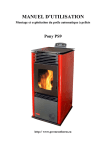
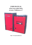
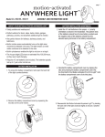
SHORT USER MANUAL for operation of automatic pellet burner of series „GP” http:// www.greenecotherm.eu Producer Address Phone Fax e-mail home page ZMM Haskovo Plc. Bulgaria, Haskovo 6300, “Saedinenie” 67 blvd. +359 800 15 145 +359 38 603070 [email protected] www.greenecotherm.eu Thank You for buying our product – automatic pellet burner of series „GP”. NOTE: in this manual is used the symbol “GP” for the entire range of pellet burner, which includes the models “GP25” and “GP32”. In the manual, however will be used a common symbol “GP”. This manual contains only basic information for the operation of the pellet burner. More detailed information for the installation and operation of the unit is given in its complete user manual, which could be found on the producer’s web site as well. SHORT USER MANUAL for operation of the automatic pellet burner of series „GP” (Edition : 10.05.2012 11:22) p. 2/11 1. Description of the automatic pellet burner “GP” is automatic pellet burner, which utilizes wood pellets. The burner is designed to be installed on already operating heating boilers or other equipment. The installed burner operates on wood pellets and other biomass fuel. The control potentiometer allows easy adjustment of the thermal capacity by the end user. The pellet burner of series “GP” could utilize the following fuels: Wood pellet with diameter 6 and 8, class ENplus-A1 according to standard ENplus, or category: A, AB, B according to methodology developed and applied by the unit-producer company; Pre-dried pits (from cherries for example); Fuel mixture – pellets and pits (for example mixture ratio could be 50% 50%); 2. Description of the burner Бункер с гориво Pellet hopper „BP” “BP” Figure 2.1. Correct position of the fuel transport auger – inclination of 45o; 45о Бункер с гориво Pellet hopper „BP” “BP” ≠45 Figure 2.2. Incorrect position of the fuel transport auger – the inclination angle is not 45o; The fuel hopper of the figures is used for illustrative purposes only, it’s not a module of the pellet burner’s kit. p. 3/11 Interface panel “Back fire” safety alarm thermo-probe Photosensor Combustion chamber Control board of the burner Flap and air supply fan Power supply cable Auger power supply plug Figure 2.3. Section view of the pellet burner’s main module components; ATTENTION: the flexible hose, which connects the transport auger and the main module, should be stretched in order to prevent any pellet particles blockage; Transparent window for operating mode monitoring Wood pellets delivery pipe (to the combustion chamber) and back fire temperature sensor Attachment flange of the burner’s main module Combustion chamber’s grate Photosensor Figure 2.4. Side view of the burner’s main module; p. 4/11 2.1. Interface panel of the automatic pellet burner of series “GP” “POWER” indicator lamp Thermal capacity control potentiometer “START” indicator lamp Figure 2.5. Interface panel with indicator lamps and control elements of the automatic pellet burner. Elements of the interface panel and their function: Indicator lamp “POWER” – indicates the presence of power supply in the burner’s main module; Indicator lamp “START” – indicates the presence of START (ON) signal of the pellet burner; Potentiometer– controls the thermal capacity of the pellet burner; 3. Pellet burner operation and maintenance In the following text are given only the basic requirements for reliable and efficient operation of the pellet burner. 3.1. 3.2. Basic requirements for operation of the automatic pellet burner At operation the pellet burner should be checked on regular basis by the end user or the system maintenance staff; It is not recommended to increase the thermal capacity of the burner above its nominal one; The combustion process ash residue should be collected in fireproof containers with lids and after cooling the mineral mass should be deposited at appropriate sites; Switching ON the burner The power supply of the burner is provided by the power supply module of the heat consumer appliance, having attached the burner. In case the burner has been in operating mode and the power supply has been interrupted, at power supply renewal, the burner start or continues its operation automatically. p. 5/11 Switching ON the control module, in most of the cases this is the hot water boiler’s operating thermostat. Figure 3.1. Switching ON the hot water boiler’s operating thermostat. The showed control elements are used for illustrative purposes only and do not belong to the pellet burner’s installation kit; The room thermostat should be switched ON as well, if such module is connected to the system, verify that the burner has the start signal. NOTE: At the initial start-up process of the pellet burner the fuel transport auger should be filled with pellets. This empty auger’s filling-up process has duration of approximately 15 – 20 minutes. In order to fill-up the auger one should plug the auger power supply into common power supplied electrical plug and wait until the pellets start to fall out of the exit pipe of the auger. After the auger has been filled-up, its power supply plug should be connected into the burner’s main module socket in order to be operated. Figure 3.2. Manual power supply of the auger to common power supply socket. ATTENTION: in case the transport auger power supply is not connected in the main module’s power socket, the burner’s control module goes into alarm mode (which is indicated with permanent lighting of the yellow and the green LEDs). After the auger’s power supply has been plugged into burner’s socket, the burner should be restarted. Figure 3.3. Manual plugging of the transport auger power supply into the burner’s socket. p. 6/11 ATTENTION: It is not recommended to position the thermal capacity potentiometer into the color scale red region – it is possible to operate the burner at thermal capacity exceeding the nominal one of the burner. The pellet burner operation in the thermal capacity potentiometer red region is allowed for short period of time, when the heat consumer requires increased thermal capacity or when the available fuel has calorific value less than the nominal fuel. Figure 3.4. Not recommended adjustment of the pellet burner thermal capacity. If the photosensor does not sense the presence of the combustion process, the ignition algorithm process is activated again. In case of ignition failure, the reasons could be: Absence of fuel in the transport auger; Presence of ash residue (also some slagging) on the burner’s grate; Dirty photosensor – clean the photosensor from the deposited tar and ash particles; When the burner operates and there is stable combustion, the red LED is light permanently, while the green and the yellow LEDs are blinking serially. Combustion process active indication (the red LED is lit up) Figure 3.5. Stable combustion process and its indication – the red light emitting diode (LED) is lighted. p. 7/11 3.3. Description of the LEDs, installed on the pellet burner control board The green and the yellow LEDs are blinking one after another and indicate certain operating modes and messages, which are used to estimate the pellet burner status. The number of the blinking of the green and the yellow LEDs indicate the adjustment of the burner. For mode information – refer to burner’s user manual. 3.4. Pellet burner thermal capacity adjustment The adjustment of the pellet burner thermal capacity is performed by the adjustment of the position of the thermal capacity control potentiometer (parameter P2 – see the burner’s manual). NOTE : In the color scale blue region the burner operates at minimal thermal capacity; In the color scale green and the yellow region the pellet burner operates in the region of nominal thermal capacity; In the color scale red region the pellet burner operates at maximal thermal capacity; A criteria for efficient operation of the pellet burner is the color of the flame – it should be straw-yellow and transparent to some extend. 3.5. Variation of the pellet burner thermal capacity Turning the potentiometer clockwise – increases the pellet burner thermal capacity Turning the potentiometer anti clockwise – decreases the pellet burner thermal capacity Figure 3.6. Changing the thermal capacity potentiometer position. 3.6. Stopping the pellet burner operation The stopping of the burner’s operation should be made by switching OFF the following: The operating thermostat of the heat consumer unit; The room thermostat (if attached to the system); Switch „START” of the heat consumer controlled module (not part of the burner’s installation kit); p. 8/11 Figure 3.7. Do NOT in any case switch off the burner by turning off its power supply. 3.7. Cleaning and maintaining the pellet burner At cleaning the pellet burner’s grate it is required to take put the grate from the main module’s combustion chamber, as it is shown on the following figure. Combustion chamber of the burner’s main module Inclined grate of the burner’s main module Burner’s grate Figure 3.8. Side view of the pellet burner’s main module and the grate is taken out of its combustion chamber; NOTE: the burner’s grate should be taken out only after it is cooled down to safe temperature levels. Use self protection and appropriate instruments (for example working gloves and pliers) in order to take out the grate. At cleaning the burner’s grate, pay attention on the total cleaning of the grates air distributing holes. The putting of the burner’s grate is performed in two steps, as shown on the following figure: p. 9/11 1. initial grate putting step 2. Sliding under the grate and its final positioning Specialized feets of the burner’s grate Figure 3.9. Cross section of the burner, showing the steps of positioning the burner’s grate; 3.8. Description of the attached liquid crystal thermosticker, indicating the requirement for ash cleaning the hot water boiler’s heat exchanger, also the burner itself, as well as the exhaust gases duct. Detailed information of the reversible thermosticker as well as the irreversible thermosticker is given in the full version of the pellet burner user manual; The liquid crystal thermosticker is utilized to measure the temperature of the burner in near vicinity of its application – in characteristic points. The thermosticker indication gives information for the requirement of cleaning the system elements. As the indicated temperature rises, the ash cleaning is recommended to be performed in the following way: Cleaning the ash residue off the burner’s grate; If the indicated temperature is still higher than nominal range, it is recommended to clean thoroughly the ash residue, accumulated on the heat exchanger of the consumer internal surfaces; If the indicated temperature is still higher than nominal operating range, it is recommended to clean the ash residue off the exhaust gases duct, as well as the chimney. The chimney’s draught should be checked as well; p. 10/11 Inreversible thermosticker Reversible liquid crystal thermosticker Figure 3.10. Side view of the liquid crystal thermostickers; Figure 3.11. The reversible thermosticker is used to indicate the operating temperature in a specific region of the pellet burner, in near vicinity if its application. The example figure shows operating condition of increased local temperature – in the range of 80 – 85oC. Figure 3.12. The irreversible thermosticker. The figure shows the thermosticker’s nominal condition, the local temperature has not been raised up above its activation temperature level of 104oC; The indication of the reversible thermostricker should be checked on regularly. The detachment or any damages of the thermostickers violates the pellet burner’s warranty conditions. 3.9. Restarting the pellet burner’s operation The pellet burner should be restarted, when it is in alarm model. The restarting is performed by sequential powering off and back powering on the automatic short circuit breaker of the heat consumer’s power supply module. It is recommended to clean the ash residue from the burner’s grate prior restarting its operation; p. 11/11