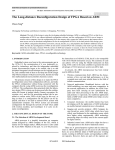
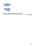
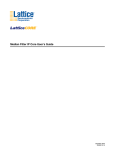
1
ispLever
CORE
TM
Parallel FIR Filter
User’s Guide
October 2005
ipug06_02.0
Lattice Semiconductor
Parallel FIR Filter User’s Guide
Introduction
This document serves as a guide containing technical information about the Lattice Parallel FIR Filter core.
Overview
The Parallel FIR Filter core is one of two FIR cores supported by Lattice. This core is designed to perform filtering
with zero latency and is well suited for real-time applications.
This Parallel FIR Filter core comes with the following documentation and files:
• Data sheet
• Protected netlist and database
• Protected RTL simulation models
• Source files for instantiating the core
Core Specification
Features
• Variable number of taps up to 64
• Data and coefficients up to 32 bits
• Output size consistent with data size
• Zero-latency operation
• Signed or unsigned data and coefficients
• Full arithmetic precision
• Fixed or loadable coefficients
• Decimation and interpolation
• Real or complex data
• Selectable rounding
• Scalable outputs
• Fully parallel implementation
• Multi-cycle modes for area/time tradeoffs
• Optimization based on symmetry of filter
General Description
Many digital systems use filters to remove noise, provide spectral shaping, or perform signal detection. Two types
of common filters that provide these functions are finite impulse response (FIR) and infinite impulse response (IIR)
filters. IIR filters are used in systems that can tolerate phase distortion. FIR filters are used in systems that require
linear phase and they have an inherently stable structure. For this reason, FIR filters are designed into a large number of systems.
The Parallel FIR Filter core can perform filtering with zero latency and is well suited for real-time applications. The
core supports two modes of computation/filtering: single-cycle mode and multi-cycle mode. In single-cycle, the filtering is done in one clock cycle and in multi-cycle, filtering is done in multiple clock cycles.
Figure 1 shows the block diagram of the Parallel FIR Filter core.
2
Lattice Semiconductor
Parallel FIR Filter User’s Guide
Figure 1. Parallel FIR Filter Core Functional Block Diagram
coeff
[0:w-1]
clk
Coefficient
Registers
Multiplier
Bank
loadc
din [0:w-1]
irdy
clk
(number of
mutipliers,
m = n/c)
Data
Scheduler
Muxed Coeff0
Tap 0
(shift reg)
Muxed Data0
Adder
Tree
Multiplier0
delayed
din 0
Tap
Array
(number of
taps = n)
Muxed Coeff1
Tap 1
(shift reg)
Muxed Data1
clk
Output
Control
Unit
dout
ordy
real_out
Multiplier1
delayed
din 1
Muxed Coeff m-1
Tap n-1
(shift reg)
Muxed Data m-1 Multiplier m-1
delayed
din n-1
Signal Descriptions
Table 1 shows the definitions of the I/O interface ports available in this core.
Table 1. Parallel FIR Filter Input and Output Signals
Port Name
Type
Active
State
Signal Description
Rising edge Clock. Master clock input to the Parallel FIR Filter core.
clk
Input
din[31..3:0]
Input
N/A
Data Input. Data to be processed. In the complex parallel I/O mode, the din bus
includes both the real and imaginary parts.
Output
N/A
Data Output. The data is the filter output. In the complex parallel I/O mode, the
dout bus includes both the real and imaginary parts.
reset_n
Input
Low
Reset. This signal resets all the delayed data signals to 0.
coeff[31..3:0]
Input
N/A
Coefficient. Coefficients for the filter are loaded sequentially while asserting the
loadc signal.
loadc
Input
High
Load Coefficient. This signal is asserted high to load the filter coefficients (data
on the coeff bus).
irdy
Input
High
Input Ready. irdy is asserted high to indicate the availability of a valid input
data in the complex-serial or multi-cycle modes.
ordy
Output
High
Output Ready. ordy is asserted high by the core to signify the availability of a
valid dout in multi-cycle or decimation modes.
real_out
Output
High
Real Part Output. real_out is asserted high to indicate that the real part of the
complex data is being output at dout. This signal is available only in complexserial mode.
dout[131..3:0]
Configuration Parameters Description
The user configuration parameters such as filter type, data width, number of taps and data types, which are configurable, are described in Table 2. These parameters are configured using IPexpress™, included with Lattice's
ispLEVER® design tools.
3
Lattice Semiconductor
Parallel FIR Filter User’s Guide
Table 2. Parallel FIR Filter Parameter Definitions
Name
Default Value
Value
Filter Type
Single-cycle
Single-cycle,
multi-cycle,
decimation or
interpolation
Data Width
8 bits
Description
Type of filter selected by the user. This determines the rest of the
parameter options.
Real: 4 to 32 bits Width of input data (W) in bits. The width of the coefficients is also
Complex: 4 to 16 equal to this parameter. For complex data types, the data width is
equal to the width of the real part and the range is from 4 to 16 bits.
bits
Number of taps (N) in the filter.
4 to 64
Number of Taps
16
Computational
Cycles
2
2 to 32
Number of cycles (C) for multi-cycle filters. Number of cycles to
perform the filtering process. The output is computed once in
cycles.
Decimation Ratio
2
2 to 32
For decimation filters. Decimation is downsampling of the bit
stream.
Interpolation Ratio
2
2 to 32
For interpolation filters. Interpolation is the reverse of decimation.
Rounding Method
Nearest
Truncation or
nearest
Arithmetic Type
Signed
Signed or
unsigned
Data Type
Real
Types of rounding available.
Specifies the type of arithmetic modules for the core. If the symmetricity of the core is even or odd, then the arithmetic type is
always signed.
Real or complex Specifies the data type of the inputs (din and coeff) and the output (dout) of the Parallel FIR core. When complex I/O mode is
selected, the arithmetic type is always signed.
Complex I/O Mode
Parallel
Parallel or serial In the parallel I/O mode, real and imaginary parts are applied on
the data bus in the same clock cycle. In the serial mode, real data
is applied in the first clock cycle, followed by the imaginary data in
the next cycle.
Output Width
Coeffs Loadable
Full precision
Fixed
4 to 97
Width of output data (W) in bits. If the width is less than the maximum output width determined by the core generator, the outputs
are scaled.
Fixed or run-time Determines if the coefficients are run-time loadable. If the coefficients are run-time loadable, the core has two additional input
loadable
ports, coeff and loadc, for loading purposes. If the coefficients
are fixed during core configuration, no additional input ports are
used.
Coefficients Format
Symmetricity
Hexadecimal
Even
Hexadecimal or The coefficient values are either in hexadecimal or decimal format.
decimal
None, even, or
odd
Specifies the impulse response of the filter. Even symmetricity
applies to symmetric impulse response, while Odd symmetricity
applies to anti-symmetric impulse response. Decimation and Interpolation filters do not have symmetricity (The value None should be
selected). If the symmetricity of the core is even or odd, then the
arithmetic type is always signed.
Functional Description
Tap Array
The Tap Array module essentially stores delayed versions or taps of input data. The number of taps of the FIR filter
and the data width are user parameters, and they are fixed at the time of core generation. The array consists of N
taps each of width W, which are organized as shift registers. All the data registers are reset when the reset_n
input is asserted. At every clock edge, the data values are shifted into the next sequential shift register inside the
Tap Array, with the first register getting the value from the input data port din.
4
Lattice Semiconductor
Parallel FIR Filter User’s Guide
Coefficient Registers
The Coefficient Registers module stores the FIR filter coefficients. The coefficients can either be loaded at run time
or can be fixed during core generation. If the user chooses to fix the coefficients, then the coeff bus and loadc
ports are not used in this module. For fixed coefficients, the values are hardcoded. If the coefficients are configured
to be loaded, they are loaded into the coeff registers sequentially at every clock edge. The coeff loading starts
at the first clock edge after loadc goes high and continues as long as loadc is active.
Data Scheduler
Data scheduling is necessary to schedule the tap and coefficient data to the multiplier bank for multi-cycle computations. This module has the necessary multiplexers to supply the tap and coefficient data to the multiplier bank in
batches. For a multi-cycle implementation with C cycles, the number of multipliers, M is equal to (N/C) rounded to
the next higher integer. For a fully parallel implementation (C = 1), the data scheduler reduces to a direct connection. The data scheduler is also used to multiplex data for optimizing decimation and interpolation filters.
Multiplier Bank
The Multiplier Bank has M number of W bit wide multipliers, where M is determined as the number of taps N
divided by the number of computational cycles C rounded to the next higher integer (M = ceil (N/C)). The number of
multipliers is equal to the number of taps for a fully parallel implementation. The input to the bank comes from the
data scheduler and the output goes to the adder tree. The maximum delay through the multiplier bank is equal to
the delay of a singe multiplier.
Adder Tree and Output Control Unit
The Adder Tree has parallel adders instantiated in a binary tree fashion. The Output Control Unit has the scaling
and rounding logic to achieve output scalability and selectable rounding. There are also data registers to provide
synchronous registered output from the filter core. For a multi-cycle or decimation filtering, an adder is present in
the block, which when combined with the output registers, makes an accumulator.
Core Operation
There are four distinct implementations of parallel FIR filter: single-cycle, multi-cycle, decimation and interpolation.
This section describes these implementation types in detail. A note on rounding and truncation is also given in this
section. Complex data type is supported in all the filter implementations. For a complex data type, the complex
input data can be either supplied all at once (complex-parallel) or in two stages, real data followed by imaginary
data (complex-serial). The following notations are used:
N
W
C
D
U
M
OW
OFW
Number of taps
Width of input data and coefficients
Number of cycles for a multi-cycle operation
Decimation ratio
Interpolation ratio
Number of multipliers, determined as M = Next higher integer to (N/C)
Output width
Output full width
Single Cycle
This is the simplest of all implementations, in that it assumes availability of sufficient resources for parallel implementation. For an N-tap filter, it uses N multipliers and N - 1 adders. The output is available on every cycle. The timing diagrams for the single-cycle implementations are given in Figures 2 and 3. As seen in the timing diagram, real
and imaginary parts of the input are supplied in successive clock cycles in complex serial mode. The data rate is
equal to half the clock rate. The input irdy should be asserted high to coincide with every valid real data at the
din port. Similarly, the core asserts the output real_out whenever the real part of the output data is placed on
the output bus.
5
Lattice Semiconductor
Parallel FIR Filter User’s Guide
Figure 2. Timing for Single-cycle, Real or Complex-parallel Mode
clk
din
2
1
internal data
processing
dout
x
x
3
6
5
4
8
7
1
2
3
4
5
6
7
8
x
1
2
3
4
5
6
7
Figure 3. Timing for Single-cycle, Complex-serial Mode
clk
din
1r
1i
2i
2r
3r
3i
4i
4r
irdy
internal data
processing
dout
x
x
1
x
x
2
x
1r
3
1i
2r
4
2i
3r
real_out
Multi-cycle
In a multi-cycle implementation, each output is computed over a period of C cycles. The implementation is similar
to the parallel implementation, except that fewer resources are used over multiple cycles. The number of multipliers
and adders used is not more than 1/Mth of those used in fully parallel implementation. There is an additional accumulator (an adder and a register combination) to accumulate the final sum through the C cycles. The timing diagrams for multi-cycle implementations are given in Figures 4 and 5.
Real and Complex-parallel Modes
The signal irdy is asserted during the first cycle of a multi-cycle operation, in the real and complex-parallel
modes. The data output of the core changes every C cycles and remains unchanged during the data cycle (each
data cycle is C clock cycles wide).The output ordy goes high during the first clock cycle of each data cycle. This
operation is shown in Figure 4.
6
Lattice Semiconductor
Parallel FIR Filter User’s Guide
Figure 4. Timing for Multi-cycle (3 Cycles), Real or Complex-parallel Mode
clk
din
1
2
irdy
internal data
processing
dout
x
1
2
x
1
3
2
ordy
Complex-serial Mode
The data and handshake signals for a typical complex-serial mode configuration (C = 3) are shown in Figure 5.
Every input data cycle has a real data cycle followed by an imaginary data cycle. Each of these real and imaginary
data cycles is C clock cycles wide. The irdy input signal must be asserted high during the first cycle of every input
data cycle.
The output data cycles also contain a real data cycle followed by an imaginary data cycle. The ordy output signal
goes high during the first clock cycle of every output real or imaginary data cycle. The real_out output signal
goes high during the first clock cycle of every output real data cycle.
Figure 5. Timing for Multi-cycle (3 Cycles), Complex-serial Mode
clk
din
1r
2r
1i
2i
3r
irdy
internal data
processing
dout
x
x
1
x
2
x
ordy
real_out
7
1r
1i
Lattice Semiconductor
Parallel FIR Filter User’s Guide
Decimation
Decimation is downsampling of the data stream. In a simple decimation filter with decimation ratio ‘D’, every Dth
sample of the input is sent to the output. The danger with downsampling is that aliasing can occur if the input signal
is not band-limited to 1/D of the original bandwidth. Therefore, to prevent aliasing, it is necessary to do a lowpass
filtering before downsampling. The decimation filter implementation is, therefore, a cascade of a lowpass filter and
a downsampler. The implementation of this is similar to a normal FIR, except that D - 1 samples are skipped at the
output, after every valid output. The output data rate is 1/Dth of the input rate. The arithmetic resources are reused
in this design, as it is not necessary to compute an output for every input sample.
The output signal, ordy, goes high during the first cycle of each data output. For, complex-serial mode, there is an
additional output, real_out, which goes high during the first cycle of every real part of the complex data.
The timing diagrams for two decimation filter implementations are shown in Figures 6 and 7.
Figure 6. Timing for Real or Complex-parallel, Decimation Mode (Ratio = 3)
clk
din
1
2
internal data
processing
dout
x
4
3
6
5
1
4
x
1
7
4
ordy
Figure 7. Timing for Complex-serial, Decimation Mode (Ratio = 3)
clk
din
1r
1i
2i
2r
3r
4r
3i
4i
5i
5r
6r
7r
6i
7i
irdy
internal data
processing
dout
x
x
1
x
4
x
1r
7
1i
4r
ordy
real_out
Interpolation
Interpolation is the reverse process of decimation. In this mode, the data is upsampled. For an interpolation ratio U,
U - 1 ‘zeros’ are introduced between any two consecutive samples and the resulting expanded stream is passed
through a lowpass filter. The operational environment of an interpolation filter is similar to a regular FIR filter, except
8
Lattice Semiconductor
Parallel FIR Filter User’s Guide
the input data rate is reduced by ‘U’ and 0’s are introduced in the taps. The timing diagrams for two Interpolation Filter implementations are shown in Figures 8 and 9.
Figure 8. Timing for Real or Complex-parallel, Interpolation Mode (Ratio = 3)
clk
din
1
internal data
processing
dout
x
2
3
x
1a
1b
1c
2a
2b
2c
x
x
1a
1b
1c
2a
2b
3a
2c
Figure 9. Timing for Complex-serial, Interpolation Mode (Ratio = 3)
clk
din
1r
2r
1i
2i
3r
irdy
internal data
dout
x
x
x
1b
1a
processing
x
x
x
1ar
2a
1c
1ai
1br
1bi
1cr
2b
1ci
2ar
2ai
real_out
Output Scaling and Rounding
When the user defined output width (OW) of the filter is less than the full output width of the filter (OFW), the outputs are scaled using a rounding scheme that is based on the parameter “rounding method”. If the rounding
method is defined as “truncation”, the least significant OFW-OW bits are simply discarded and the most significant
OW bits are retained in the output. If the rounding method is selected to be “nearest”, the most significant OW bits
are retained and they are rounded based on the value of the least significant bits that are discarded. Truncation
takes the value to the next step towards minus infinity and rounding nearest takes the value to the nearest step in
either direction.
Table 3 illustrates the output scaling and rounding for two numbers using integer, fixed point, signed and unsigned
representations. In the example, the full output width (OFW) is 8 and the desired output width (OW) is 6. Output
scaling in this case is equivalent to a division by 4.
9
Lattice Semiconductor
Parallel FIR Filter User’s Guide
Table 3. Example Description of Output Scaling and Rounding
Binary
1010 1001
1010 1011
Mode
Decimal
Full Precision
Divide by 4
Truncation
Nearest
Unsigned, integer
169
42.25
42
42
Signed, Integer
-87
-21.75
-22
-22
Unsigned, FP between bit 3 and bit 4
10.5625
2.640625
2.625
2.625
Signed, FP between bit 3 and bit 4
-5.4375
-1.359375
-1.375
-1.375
Unsigned, integer
171
42.75
42
43
Signed, Integer
-85
-21.25
-22
-21
Unsigned, FP between bit 3 and bit 4
10.6875
2.671875
2.625
2.6875
Signed, FP between bit 3 and bit 4
-5.3125
-1.328125
-1.375
-1.3125
IPexpress
The Lattice IP configuration tool, IPexpress, is incorporated in the ispLEVER software. IPexpress includes a GUI for
entering the required parameters to configure the core. For more information on using IPexpress and the
ispLEVER design software, refer to the software help and tutorials included with ispLEVER. For more information
on ispLEVER, see the Lattice web site at: www.latticesemi.com/software.
Available Configuration(s) for Evaluation
Table 4 lists the available configuration with the corresponding parameters. To obtain the evaluation version of this
core, visit the Lattice web site at www.latticesemi.com.
Table 4. Available Core Configuration
Input Data
Width
Parameter File Name
fir_para_xp_1_002.lpc
8 bits
No. of
Taps
FIR
Type
16
Single
cycle
Symmetry
Arithmetic
Type
Data
Type
Output Data
Width (Full data
width)
Symmetric
Signed
Real
Full (21)
10
Fixed
Coefficients
60, 44, D9, 37,
35, 16, F6, 39
(HEX)
Lattice Semiconductor
Parallel FIR Filter User’s Guide
Figure 10. Dialog Box for Configuring the Parallel FIR Filter Core
Figure 11. Dialog Box for Specifying the Coefficients
11
Lattice Semiconductor
Parallel FIR Filter User’s Guide
References and Related Information
The following document will provide further information on implementing this core:
• ispLEVER Software User Manual
In addition to this Parallel FIR Filter core, Lattice also offers the Serial FIR Filter for similar applications. For more
information, refer to the following document:
• Serial FIR Filter Core User’s Guide
Technical Support Assistance
Hotline: 1-800-LATTICE (North America)
+1-503-268-8001 (Outside North America)
e-mail: [email protected]
Internet: www.latticesemi.com
12
Lattice Semiconductor
Parallel FIR Filter User’s Guide
Appendix for ispXPGA® FPGAs
Table 5. Performance and Resource Utilization1
Parameter File
Parameters
LUT4s2
ispXPGA
PFUs3
Registers
External
Pins
System
EBRs
fMAX1
(MHz)
fir_para_xp_1_002.lpc
See Table 6
858
297
149
31
None
51
1. Performance and utilization characteristics are generated using LFX1200B-04FE680C in Lattice’s ispLEVER 3.x software. The evaluation
version of this IP core only works on this specific device density, package, and speed grade.
2. Look-Up Table (LUT) is the standard logic block of the ispXPGA. LUT4 is a 4-input LUT.
3. Programmable Function Unit (PFU) contains LUTs and other resources.
Supplied Netlist Configurations
The Ordering Part Number (OPN) is FIR-PARA-XP-N1. Table 6 lists the Lattice-specific netlist that are available in
the Evaluation Package, which can be downloaded from the Lattice web site at www.latticesemi.com.
Table 6. Description of Netlist Configuration
Input Data
Width
Parameter File Name
fir_para_xp_1_002.lpc
8 bits
No. of
Taps
FIR
Type
16
Single
cycle
Symmetry
Arithmetic
Type
Data
Type
Output Data
Width (Full data
width)
Symmetric
Signed
Real
Full (21)
13
Fixed
Coefficients
60, 44, D9, 37,
35, 16, F6, 39
(HEX)