1
System Console User Guide
101 Innovation Drive
San Jose, CA 95134
www.altera.com
Software Version:
Document Date:
9.1
November 2009
Copyright © 2009 Altera Corporation. All rights reserved. Altera, The Programmable Solutions Company, the stylized Altera logo, specific device designations, and all other
words and logos that are identified as trademarks and/or service marks are, unless noted otherwise, the trademarks and service marks of Altera Corporation in the U.S. and other
countries. All other product or service names are the property of their respective holders. Altera products are protected under numerous U.S. and foreign patents and pending applications, maskwork rights, and copyrights. Altera warrants performance of its semiconductor products to current specifications in accordance with Altera's standard warranty,
but reserves the right to make changes to any products and services at any time without notice. Altera assumes no responsibility or liability arising out of the application or use of
any information, product, or service described herein except as expressly agreed to in writing by Altera Corporation. Altera customers are advised to obtain the latest version of
device specifications before relying on any published information and before placing orders for products or services.
UG-01041-1.3
Contents
Chapter 1. System Console Commands
Introduction . . . . . . . . . . . . . . . . . . . . . . . . . . . . . . . . . . . . . . . . . . . . . . . . . . . . . . . . . . . . . . . . . . . . . . . . . . . . 1–1
Console Commands . . . . . . . . . . . . . . . . . . . . . . . . . . . . . . . . . . . . . . . . . . . . . . . . . . . . . . . . . . . . . . . . . . . . . 1–3
Programmable Logic Device (PLD) Commands . . . . . . . . . . . . . . . . . . . . . . . . . . . . . . . . . . . . . . . . . . . . . 1–4
Board Bring-Up Commands . . . . . . . . . . . . . . . . . . . . . . . . . . . . . . . . . . . . . . . . . . . . . . . . . . . . . . . . . . . . . . 1–4
JTAG Debug Command . . . . . . . . . . . . . . . . . . . . . . . . . . . . . . . . . . . . . . . . . . . . . . . . . . . . . . . . . . . . . . . . . . 1–4
Clock and Reset Signal Commands . . . . . . . . . . . . . . . . . . . . . . . . . . . . . . . . . . . . . . . . . . . . . . . . . . . . . . . . 1–5
Avalon-MM and Interface Commands . . . . . . . . . . . . . . . . . . . . . . . . . . . . . . . . . . . . . . . . . . . . . . . . . . . . . 1–5
Processor Commands . . . . . . . . . . . . . . . . . . . . . . . . . . . . . . . . . . . . . . . . . . . . . . . . . . . . . . . . . . . . . . . . . . . . 1–6
Bytestream Commands . . . . . . . . . . . . . . . . . . . . . . . . . . . . . . . . . . . . . . . . . . . . . . . . . . . . . . . . . . . . . . . . . . 1–7
Design Plugin Commands . . . . . . . . . . . . . . . . . . . . . . . . . . . . . . . . . . . . . . . . . . . . . . . . . . . . . . . . . . . . . . . . 1–7
Interactive Help . . . . . . . . . . . . . . . . . . . . . . . . . . . . . . . . . . . . . . . . . . . . . . . . . . . . . . . . . . . . . . . . . . . . . . . . 1–12
Chapter 2. System Console Examples
Introduction . . . . . . . . . . . . . . . . . . . . . . . . . . . . . . . . . . . . . . . . . . . . . . . . . . . . . . . . . . . . . . . . . . . . . . . . . . . . 2–1
LED Light Show Example . . . . . . . . . . . . . . . . . . . . . . . . . . . . . . . . . . . . . . . . . . . . . . . . . . . . . . . . . . . . . . . . 2–1
JTAG Examples . . . . . . . . . . . . . . . . . . . . . . . . . . . . . . . . . . . . . . . . . . . . . . . . . . . . . . . . . . . . . . . . . . . . . . . . . 2–3
Verify JTAG Chain . . . . . . . . . . . . . . . . . . . . . . . . . . . . . . . . . . . . . . . . . . . . . . . . . . . . . . . . . . . . . . . . . . . . 2–3
Verify Clock . . . . . . . . . . . . . . . . . . . . . . . . . . . . . . . . . . . . . . . . . . . . . . . . . . . . . . . . . . . . . . . . . . . . . . . . . . 2–4
Checksum Example . . . . . . . . . . . . . . . . . . . . . . . . . . . . . . . . . . . . . . . . . . . . . . . . . . . . . . . . . . . . . . . . . . . . . . 2–5
Nios II Processor Example . . . . . . . . . . . . . . . . . . . . . . . . . . . . . . . . . . . . . . . . . . . . . . . . . . . . . . . . . . . . . . . . 2–7
Additional Information
Revision History . . . . . . . . . . . . . . . . . . . . . . . . . . . . . . . . . . . . . . . . . . . . . . . . . . . . . . . . . . . . . . . . . . . . Info-–1
How to Contact Altera . . . . . . . . . . . . . . . . . . . . . . . . . . . . . . . . . . . . . . . . . . . . . . . . . . . . . . . . . . . . . . . Info-–1
Typographic Conventions . . . . . . . . . . . . . . . . . . . . . . . . . . . . . . . . . . . . . . . . . . . . . . . . . . . . . . . . . . . . Info-–1
© November 2009
Altera Corporation
System Console User Guide
iv
System Console User Guide
© November 2009 Altera Corporation
1. System Console Commands
UG-01041-1.1
Introduction
The System Console performs low-level hardware debugging of SOPC Builder
systems. The System Console provides read and write access to the IP cores
instantiated in your SOPC Builder system. You can use the System Console for the
initial bring-up of your printed circuit board and low-level testing. The System
Console is the appropriate tool for all of the following system debugging tasks:
■
Verifying that the clock is toggling
■
Verifying component pinouts
■
Testing memories and peripheral devices
■
Determining the value of the reset signal
■
Perform loopback testing of Avalon® Streaming (Avalon-ST) interfaces
The System Console runs in command line mode. You can work interactively or run a
Tcl script. The System Console prints responses to your commands in the terminal
window. To facilitate debugging with the System Console, you can include one of the
four SOPC Builder components with interfaces that the System Console can use to
send commands and receive data. Table 1–1 lists these components.
Table 1–1. SOPC Builder Components for Communication with the System Console (Note 1)
Component Name
Nios®
The
enabled
Debugs Components with the Following Interface Types
II processor with JTAG debug
Components that include an Avalon® Memory-Mapped (Avalon-MM)
slave interface. The JTAG debug module can also control the Nios II
processor for debug functionality, including starting, stopping, and
stepping the processor.
JTAG to Avalon master bridge
Components that include an Avalon-MM slave interface
Avalon Streaming (Avalon-ST) JTAG Interface
Components that include an Avalon-ST interface
JTAG UART
The JTAG UART is an Avalon-MM slave device that can be used in
conjunction with System Console to send and receive byte streams.
Note to Table 1–1:
(1) The System Console can also send and receive byte streams from any SLD node whether it is instantiated in SOPC Builder component provided
by Altera®, a custom component, or part of your Quartus® II project; however, this approach requires detailed knowledge of the JTAG
commands.
f
© November 2009
To learn more about these components refer to the following web pages and
documents:
■
The Nios II Processor product web page
■
SPI Slave/JTAG to Avalon Master Bridge Cores chapter in volume 5 of the Quartus II
Handbook
■
Avalon-ST JTAG Interface Core chapter in volume 5 of the Quartus II Handbook
■
sld_virtual_jtag MegaFunction User Guide
■
JTAG UART Core chapter in volume 5 of the Quartus II Handbook
Altera Corporation
System Console User Guide
1–2
Chapter 1: System Console Commands
Introduction
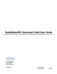
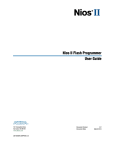
Figure 1–1 illustrates the interfaces of these components that the System Console can
use.
Figure 1–1. Interfaces (Paths) the System Console Can Use to Send Commands
Connections You Make
in SOPC Builder
Transparent Connections
Nios II Processor
Avalon-MM
Master
JTAG Avalon Master Bridge
User Component
Avalon-MM
Slave
Virtual JTAG
Interface
or
Avalon-MM
Master
Virtual JTAG
Interface
Avalon-ST JTAG Interface
User Component
Avalon-ST
Source
and Sink
Avalon-ST
Source and
Sink
Quartus II JTAG Logic
Virtual
JTAG Hub
(Soft IP)
JTAG TAP
Controller
(Hard IP)
To
Host PC
Running
System Console
Virtual JTAG
Interface
JTAG UART
Avalon-MM
Slave
Legacy
JTAG
Interface
Altera recommends that you also include the following components in your system:
■
On-chip memory
■
JTAG UART
■
System ID core
In its initial configuration, the System Console provides seven different types of
services. Different modules can provide the same type of service. For example, both
the Nios II processor and the JTAG to Avalon Bridge master provide the master
service; consequently, you can use the master commands to access both of these
modules.
If your system includes a Nios II/f core with a data cache it may complicate the
debugging process. If you suspect that writes to memory from the data cache at
nondeterministic intervals are overwriting data written by the System Console, you
can disable the cache of the Nios II/f core while debugging.
System Console User Guide
© November 2009 Altera Corporation
Chapter 1: System Console Commands
Console Commands
1–3
You can start the System Console from a Nios II command shell.
1. Choose All Programs > Altera > Nios II EDS <version> Command Shell
(Windows Start menu) to run a Nios II command shell.
2. To start the System Console, type the following command:
system-console r
You can customize your System Console environment by adding commands to the
<quartus_install_dir>/sopc_builder/system_console_macros/system_console_rc.tcl
file. On startup, System Console automatically runs any Tcl commands in this file.
1
Many of the System Console commands do not work unless you are
connected to a system using a programming cable.
The following sections describe how to use each type of command.
Console Commands
The console commands enable testing. You can use console commands to identify a
module by its path, and to open and close a connection to it. The path that identifies
a module is the first argument to most of the other System Console commands. To
exercise a module, follow these steps:
1. Identify a module by specifying the path to it, using the get_service_paths
command.
2. Open a connection to the module using the open_service command.
3. Run Tcl and System Console commands to test the module.
4. Close a connection to a module using the close_service command.
Table 1–2 describes the syntax of the five console commands.
Table 1–2. Console Commands
Command
get_service_types
Arguments
Function
—
Returns a list of the 7 services that the System Console
manages: master, bytestream, processor, sld,
jtag_debug, device, and plugin.
get_service_paths
<service_type_name>
Returns a list of paths to nodes that implement the
requested service type.
open_service
<service_type_name>,
<service_path>
Opens the service type specified.
close_service
<service_type_name>,
<service_path>
Closes the service type specified.
is_service_open
<service_type_name>,
<service_path>
Returns 1 if the service type provided by the path is
open, 0 if the service type is closed.
© November 2009
Altera Corporation
System Console User Guide
1–4
Chapter 1: System Console Commands
Programmable Logic Device (PLD) Commands
Programmable Logic Device (PLD) Commands
The PLD commands provide access to programmable logic devices on your board.
Before using these commands, you must identify the path to the programmable logic
device on your board using the get_service_paths command described in
Table 1–2.
Table 1–3 describes the PLD commands.
Table 1–3. PLD Commands
Command
Arguments
Function
device_download_sof
<device_path>,
<sof_file>
This command loads the specified SRAM object file
(.sof) file to the device specified by the path.
device_load_jdi
<device_path>,
<jdi_file>
This command renames the Tcl interface layer's
nodes to the names specified in the JTAG debug
interface (.jdi) file, making your design easier to
understand.
Board Bring-Up Commands
The board bring-up commands allow you to test your system. These commands are
presented in the order that you would use them during board bring-up, including the
following four stages:
1. Verify JTAG connectivity
2. Verify the clock and reset signals
3. Verify memory and other peripheral interfaces
4. Verify basic Nios II processor functionality
1
The System Console is intended for debugging the basic hardware functionality of
your Nios II processor, including its memories and pinout. Once the hardware is
functioning correctly, you can refer to the Nios II Software Build Tool Reference in the
Nios II Software Developer’s Handbook for further software debugging. If you are writing
device drivers, you may want to use the System Console and the Nios II software
build tools together to debug your code.
JTAG Debug Command
You can use this command to verify the functionality and signal integrity of your
JTAG chain. Your JTAG chain must be functioning correctly to debug the rest of your
system. To verify signal integrity of your JTAG chain, Altera recommends that you
provide an extensive list of byte values. Table 1–4 lists this command.
System Console User Guide
© November 2009 Altera Corporation
Chapter 1: System Console Commands
Clock and Reset Signal Commands
1–5
Table 1–4. JTAG Commands
Command
jtag_debug_loop
Arguments
Function
Loops the specified list of bytes through a loopback of tdi and
tdo of a system-level debug (SLD) node. Returns the list of byte
values in the order that they were received. Blocks until all bytes
are received. Byte values are given with the 0x (hexadecimal)
prefix and delineated by spaces.
<path>,
<list_of_byte_
values>
Clock and Reset Signal Commands
The next stage of board bring-up tests the clock and reset signals. Table 1–5 lists the
three commands to verify these signals. You can use these commands to verify that
your clock is toggling and that the reset signal has the expected value.
Table 1–5. Clock and Reset Commands
Command
Argument
Function
jtag_debug_sample_clock <path>
Returns the value of the clock signal of the system clock that drives the
module's system interface. The clock value is sampled asynchronously;
consequently, you may need to sample the clock several times to
guarantee that it is toggling.
jtag_debug_sample_reset <path>
Returns the value of the reset signal of the system reset that drives the
module's system interface.
jtag_debug_sense_clock
Returns the result of a sticky bit that monitors for system clock activity. If
the clock has ever toggled, the bit is 1. Returns true if the bit has ever
toggled and otherwise returns false. The sticky bit is reset to 0 on read.
<path>
Avalon-MM and Interface Commands
These commands allow you to test the modules included in your FPGA. You can read
or write the Avalon-MM interfaces using the master read and write commands.
Additionally, you can use the SLD commands to shift values into the instruction and
data registers of SLD nodes and read the previous value. Table 1–6 lists these
commands.
Table 1–6. Module Commands (Note 1)
Command
Arguments
Function
Avalon-MM Master Commands
master_write_memory <path>, <address>,
<list_of_byte_values>
master_write_8
<path>, <address>,
<list_of_byte_values>
master_write_16
<path>, <address>,
<list_of_byte_values>
master_write_32
<path>, <address>,
<list_of_byte_values>
© November 2009
Altera Corporation
Writes the specified value to the specified path and
address. Values are given in hexadecimal format with
the 0x prefix and delineated by spaces.
System Console User Guide
1–6
Chapter 1: System Console Commands
Processor Commands
Table 1–6. Module Commands (Note 1)
Command
Arguments
master_read_memory
<path>,
<base_address>,
<size_in_bytes>
master_read_8
<path>,
<base_address>,
<size_in_bytes>
master_read_16
<path>,
<base_address>,
<size_in_multiples_of_
16_bits>
master_read_32
<path>,
<base_address>,
<size_in_multiples_of_
32_bits>
Function
Returns a list of read values.
SLD Commands
sld_access_ir
<path>, <value>,
<timeout> (in µseconds)
Shifts the instruction value into the instruction register
of the specified node. Returns the previous value of the
instruction. If the timeout value is set to 0, the operation
never times out. A suggested starting value for
timeout is 1000 µseconds.
sld_access_dr
<path>,
<size_in_bits>,
<timeout> (in µseconds),
<list_of_byte_values>
Shifts the byte values into the data register of the SLD
node up to the size in bits specified. If the timeout
value is set to 0, the operation never times out. Returns
the previous contents of the data register. A suggested
starting value for timeout is 1000 µseconds.
sld_lock
sld_lock <path>
<timeout> (in mseconds)
Locks the SLD chain to guarantee exclusive access. If
the SLD chain is already locked, tries for <timeout>
mseconds before returning -1, indicating an error.
Returns 0 if successful.
sld_unlock
sld_unlock <path>
Unlocks the SLD chain.
Notes to Table 1–6:
(1) Transfers performed in 16- and 32-bit sizes are packed in little endian format.
Processor Commands
These commands allow you to start, stop, and step through software running on a
Nios II processor. They also allow you to read and write the processor’s registers.
Table 1–7 lists the commands.
Table 1–7. Processor Commands (Part 1 of 2)
Command
Arguments
Function
processor_run
<path>
Puts the processor into run mode.
processor_stop
<path>
Puts the processor into stop mode.
processor_step
<path>
Executes one assembly instruction.
processor_get_register <path>
_names
System Console User Guide
Returns a list with the names of all of the processor's
accessible registers.
© November 2009 Altera Corporation
Chapter 1: System Console Commands
Bytestream Commands
1–7
Table 1–7. Processor Commands (Part 2 of 2)
Command
Arguments
Function
processor_get_register <path>,
<register_names>
Returns the value of the specified register.
processor_set_register <path>,
<register_names>
Sets the value of the specified register.
Bytestream Commands
These commands provide access to modules that produce or consume a stream of
bytes. One example of a module that operates on byte streams is the JTAG UART.
Bytestream service can be built on top of SLD services which transfer bits. You can use
the bytestream service to communicate directly to the Altera JTAG Interface and then
drive Avalon-ST components.Table 1–8 lists the commands.
Table 1–8. Bytestream Commands
Command
Arguments
Function
bytestream_send
<path>,
<list_of_byte_values>
Sends the list of byte values on the specified path.
Values are in hexadecimal format and delineated by
spaces.
bytestream_receive
<path>,
<number_of_bytes>
Returns a list of received bytes.
Design Plugin Commands
The design plugin commands allow you to extend the functionality of the System
Console. To use a plugin, you must enable it, using the following procedure:
1. Identify the available plugins using the get_service_paths command.
2. Enable a plugin by specifying the path to it, using the get_service_paths and
plugin_enable commands. For example, the following commands enable the
DesignsPluginProvider plugin
a. get_service_paths plugin r
b. set design_plugin [lindex [get_service_paths plugin] 2]r
The get_service_paths command always returns a list. You must index into
the list using the lindex command. In this case, the variable design_plugin is
the third element on the this, (starting from 0); however, if you enable more
plugins, its position on the list may change.
c. plugin_enable $design_plugin r
3. Run System Console plugin commands to test the component.
4. Disable a plugin using the plugin_disable command.
© November 2009
Altera Corporation
System Console User Guide
1–8
Chapter 1: System Console Commands
Design Plugin Commands
The DesignsPluginProvider allows the System Console to scan your project
directory for files of interest, including your Quartus II project file (.qpf) and SOPC
Information File (.sopcinfo) file. Using these files, the System Console identifies
Avalon-MM slave components in your design. You can use two Avalon-MM slave
components, the Avalon-ST Data Pattern Checker and the Avalon-ST Data Pattern
Checker, in conjunction with the System Console to test Avalon-ST interfaces in
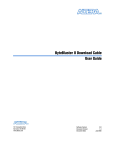
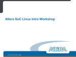
loopback mode. Figure 1–2 illustrates these components being used to perform a
loopback test for a custom component with Avalon-ST interfaces.
Figure 1–2. Using the Data Pattern Generator and Checker To Test a Custom Component with Avalon-ST Interfaces
Data Pattern Checker
Avalon-ST
Pattern In
Avalon-MM
CSR (Slave)
Custom Component
JTAG Avalon Master Bridge
Quartus II JTAG Logic
Avalon-MM
Master
Virtual
JTAG Hub
(Soft IP)
Avalon-ST
Receive
Avalon-MM
Slave
Loopback
Virtual JTAG
Interface
Avalon-ST
Transmit
JTAG TAP
Controller
(Hard IP)
To
Host PC
Running
System
Console
Data Pattern Generator
Avalon-ST
Pattern Out
Avalon-MM
CSR (Slave)
Table 1–9 lists the design plugin commands.
Table 1–9. Plugin Commands (Part 1 of 4)
Command
Arguments
Funct
Plugin Service Type Commands
plugin_enable
<plugin-path>
Enables the plugin specified b
enabled, you can retrieve the
<service_type_name>
checkers using the get_ser
get_service_types com
plugin_disable
<plugin-path>
Disables the plugin specified
is_plugin_enabled
<plugin-path>
Returns a non-zero value whe
path is enabled.
System Console User Guide
© November 2009 Altera Corporation
Command
Arguments
Function
Design Service Type Commands
Altera Corporation
design_load
<quartus-project-path> or
<qpf-file-path>
Loads a model of a Quartus II design into the System
Console. For example, if your .qpf file is in
c:/projects/loopback, type the following command:
design_load /projects/loopback
design_link
<design-path>, <deviceservice-path>
Links a Quartus II logical design with a physical device.
For example, you can link a Quartus II design called
2c35_quartus_design to a 2c35 device. After you create
this link, the System Console creates the appropriate
correspondences between the logical and physical
submodules of the Quartus II project. Example 1–1 on
page 1–12 shows a transcript illustrating the
design_load and design_link commands.
Chapter 1: System Console Commands
Design Plugin Commands
© November 2009
Table 1–9. Plugin Commands (Part 2 of 4)
Note that the System Console does not verify that the link
is valid, so that if you create an incorrect link, the System
Console does not report an error.
Data Pattern Generator Service Type Commands
data_pattern_generator_start
<service-path>
Starts the data pattern generator.
data_pattern_generator_stop
<service-path>
Stops the data pattern generator.
data_pattern_generator_is_generating
<service-path>
Returns non-zero if the generator is running.
data_pattern_generator_inject_error
<service-path>
Injects a 1-bit error into the generator's output.
1–9
System Console User Guide
1–10
System Console User Guide
Table 1–9. Plugin Commands (Part 3 of 4)
Command
Arguments
data_pattern_generator_set_pattern
<service-path>,
<pattern-name>
Function
Sets the output pattern set pattern specified by the
<pattern-name>. In all, 6 patterns are available, 4
are pseudo-random binary sequence s (PRBS) and 2 are
high and low frequency. The following pattern names are
defined:
■
PRBS7
■
PRBS15
■
PRBS23
■
PRBS31
■
HF–outputs a high frequency, constant pattern of
alternating 0s and 1s
■
LF–outputs a low frequency, constant pattern of
10b’1111100000 for 10-bit symbols and
8b’11110000 for 8-bit symbols
<service-path>
Returns currently selected output pattern.
data_pattern_generator_get_available_patterns
<service-path>
Returns a list of available data patterns by name.
data_pattern_generator_enable_preamble
<service-path>
Enables the preamble mode at the beginning of
generation.
data_pattern_generator_disable_preamble
<service-path>
Disables the preamble mode at the beginning of
generation.
data_pattern_generator_is_preamble_enabled
<service-path>
Returns a non-zero value if preamble mode is enabled.
data_pattern_generator_set_preamble_word
<service-path>,
<preamble-word>
Sets the preamble word.
data_pattern_generator_get_preamble_word
<service-path>
Gets the preamble word.
data_pattern_generator_set_preamble_beats
<service-path>
<number-of-preamble-beats>
Sets the number of beats to send out the in the preamble
word.
data_pattern_generator_get_preamble_beats
<service-path>
Returns the currently set number of beats to send out the
preamble word.
Data Pattern Checker Commands
data_pattern_checker_start
<service-path>
Starts the checker.
data_pattern_checker_stop
<service-path>
Stops the checker.
Chapter 1: System Console Commands
Design Plugin Commands
© November 2009 Altera Corporation
data_pattern_generator_get_pattern
Command
Arguments
Function
Altera Corporation
data_pattern_checker_is_checking
<service-path>
Returns a non-zero value if the checker is running.
data_pattern_checker_is_locked
<service-path>
Returns non-zero if the checker is locked onto the
incoming data.
data_pattern_checker_set_pattern
<service-path>,
<pattern-name>
Sets the expected pattern to the one specified by the
<pattern-name>.
data_pattern_checker_get_pattern
<service-path>
Returns the currently selected expected pattern by name.
data_pattern_checker_get_available_patterns
<service-path>
Returns a list of available data patterns by name.
data_pattern_checker_get_data
<service-path>
Returns a list of the current checker data, providing the
number of bits and the number of errors.
data_pattern_checker_reset_counters
<service-path>
Resets the bits and error counters inside the checker.
Chapter 1: System Console Commands
Design Plugin Commands
© November 2009
Table 1–9. Plugin Commands (Part 4 of 4)
1–11
System Console User Guide
1–12
Chapter 1: System Console Commands
Interactive Help
Example 1–1 shows how to load and link a Quartus II design.set_
Example 1–1. Loading and Linking a Design
% get_service_paths plugin
/plugins/com.altera.systemconsole.plugin.pli.PliDeviceProvider
/plugins/com.altera.systemconsole.transceivers.internal.TransceiverPluginProvider
/plugins/com.altera.systemconsole.designs.internal.DesignsPluginProvider
/plugins/com.altera.systemconsole.internal.plugin.memory.MemoryPluginProvider
/plugins/com.altera.systemconsole.internal.debugger.nios2.Nios2Support
/plugins/com.altera.systemconsole.internal.debugger.Debugger
/plugins/com.altera.systemconsole.internal.plugin.jtag.sld.SLDConnectionProvider
% set design_plugin [lindex [get_service_paths plugin] 2]
/plugins/com.altera.systemconsole.designs.internal.DesignsPluginProvider
% plugin_enable $design_plugin
Enabling plugin: com.altera.systemconsole.designs.internal.DesignsPluginProvider
% get_service_paths device
{/connections/USB-Blaster [USB-0]/EP2C35}
% set device_path [lindex [get_service_paths device] 0]
/connections/USB-Blaster [USB-0]/EP2C35
% design_load /projects/9.1/standard
QuartusDesignFactory elaborating \projects\9.1\standard
QuartusDesignFactory found SOF File at NiosII_cycloneII_2c35_standard.sof
QuartusDesignFactory found JDI File at NiosII_cycloneII_2c35_standard.jdi
QuartusDesignFactory found SOPC Info File at
\projects\9.1\standard\NiosII_cycloneII_2c35_standard_sopc.sopcinfo
% set design_path [lindex [get_service_paths design] 0]
/designs/standard
% design_link $design_path $device_path
Created a link from /designs/standard to /connections/USB-Blaster [USB-0]/EP2C35.
Created a link from /designs/standard/NiosII
cycloneII_2c35_standard_sopc.sopcinfo/cpu.data_master to /connections/USB-Blaster
[USB-0]/EP2C35/cpu.
Created a link from
/designs/standard/NiosII_cycloneII_2c35_standard_sopc.sopcinfo/cpu.data_master/jtag_
uart.avalon_jtag_slave to /connections/USB-Blaster [USB-0]/EP2C35/jtag_uart
Interactive Help
Typing help help into the System Console lists all available commands. Typing
help <command name> provides the syntax of individual commands. The System
Console provides command completion if you type the beginning letters of a
command and then press the Tab key.
1
System Console User Guide
The System Console interactive help commands only provide help for enabled
services; consequently, typing help help does not display help for a plugin unless
you have enabled it.
© November 2009 Altera Corporation
2. System Console Examples
UG-01041-1.1
Introduction
This chapter uses three different SOPC Builder systems to demonstrate the
functionality of the System Console. The System-Console.zip file contains design files
for the first two example systems. This zip file includes files for both the Nios II
Development Kit Cyclone® II Edition and the Nios II Development Kit Stratix® II
Edition. You can download the design files for the example designs from the Altera
website. A hyperlink to the design files appears next to this document on the User
Guide web page.
The first example Tcl script creates a LED light show on your board. The SOPC
Builder system for this example includes two modules: a JTAG to Avalon master
bridge and a PIO core. The JTAG to Avalon master bridge provides a connection
between your development board and SOPC Builder system via serial peripheral
interface (SPI). The PIO module provides a memory-mapped interface between an
Avalon-MM slave port and general-purpose IO ports.
f
For more information about these components refer to the SPI Slave/JTAG to Avalon
Master Bridge Cores chapter in volume 5 of the Quartus II Handbook and the PIO Core
chapter in volume 5 of the Quartus II Handbook.
The first example program sends a series of master_write_8 commands to the
JTAG Avalon master bridge. The JTAG Avalon master sends these commands to the
Avalon-MM slave port of the PIO module. The PIO I/O ports connect to FPGA pins
that are, in turn, connected to the LEDs on your development board. The write
commands to the PIO Avalon-MM slave port result in the light show.
1
The instructions for these examples assume some familiarity with the Quartus II and
SOPC Builder software.
LED Light Show Example
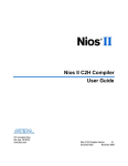
Figure 2–1 illustrates the SOPC Builder system for the first example.
© November 2009
Altera Corporation
System Console User Guide
2–2
Chapter 2: System Console Examples
LED Light Show Example
Figure 2–1. SOPC Builder System for Light Show Example
JTAG
Avalon-MM
Master
System
Interconnect
Fabric
PIO LED
(Avalon-MM
Slave)
Conduit
Interface
LEDs
To build this example system, complete the following steps:
1. On your host computer file system, locate the following directory: <Nios II EDS
install path>\examples\<verilog or vhdl>\<board version>\standard. Each
development board has a VHDL and Verilog HDL version of the design. You can
use either of these design examples.
2. Copy the standard directory to a new location. By copying the design files, you
avoid corrupting the original design and avoid issues with file permissions. This
document refers to the newly-created directory as the c:\<projects>\standard
directory.
3. Copy the System_Console.zip file to the c:\< projects>\standard directory and
unzip it. The jtag_pio_cii and jtag_pio_sii directories are created for the
Cyclone II and Stratix II development boards.
4. Choose All Programs > Altera > Nios II EDS <version> Command Shell
(Windows Start menu) to run a Nios II command shell.
5. Change to the directory for your board.
6. To program your board with the .sof file.Type the following command in the
Nios II command shell:
nios2-configure-sof <sof_name>.sof r
If your development board includes more than one JTAG cable you must specify
which cable you are communicating with as an argument to the
nios2-configure-sof <sof_name>.sof command. To do so, type the
following commands:
a. jtagconfig r
System Console User Guide
© November 2009 Altera Corporation
Chapter 2: System Console Examples
JTAG Examples
2–3
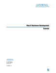
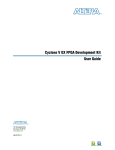
Figure 2–2. jtagconfig Output
Figure 2–2 gives sample output from the jtagconfig command. This output
shows that the active JTAG cable is number 2. Substitute the number of your JTAG
for the <cable_number> variable in the following command:
b. nios2-configure-sof -c <cable_number> <sof_name>.sof r
7. You can then run the LED light show example by typing the following command:
system-console --script=led_lightshow.tcl r
8. You can see the LEDs performing a running light demonstration. Press Ctrl+C to
stop the LED light show.
9. To see the commands that this script runs, open the led_lightshow.tcl file in your
\jtag_pio_<cii_or_sii> directory.
JTAG Examples
There are two JTAG examples. The first JTAG example gives you some practice
working with the System Console as an interactive tool. The second verifies that the
clock is toggling.
Verify JTAG Chain
In this example, you verify the JTAG chain on you board. To run this example,
complete the following steps:
1. Choose All Programs > Altera > Quartus II <version> (Windows Start menu) to
run the Quartus II software. Open the Quartus II project file, jtag_pio.qpf or
jtag_pio_sii.qpf.
2. On the Tools menu, click SOPC Builder.
3. On the SOPC Builder Tools menu, click System Console.
4. Set the path to the jtag_debug service by typing the following command:
set jd_path [lindex [get_service_paths jtag_debug] 0] r
The get_service_paths command always returns a list, even if the list has a
single item; consequently, you must index into the list using the lindex
command. In this case, the variable jd_path is assigned the string that is the 0th
element of the list.
5. Open the jtag_debug service by typing the following command:
open_service jtag_debug $jd_path r
6. Set up a list of byte values to test the chain by typing the following command:
set values [list 0xaa 0x55 0xaa 0x55 0xaa 0x55 0xaa 0x55 0xaa 0x55
0xaa 0x55 0xaa 0x55 0xaa 0x55 0xaa 0x55]r
© November 2009
Altera Corporation
System Console User Guide
2–4
Chapter 2: System Console Examples
JTAG Examples
7. Loop the values by typing the following command:
jtag_debug_loop $jd_path $values r
If the jtag_debug_loop command is successful, you should see the values that
you sent reflected in the System Console. Figure 2–3 shows the transcript from this
interactive session.
Figure 2–3. The jtag_debug_loop Command
8. Close the jtag_debug service by typing the following command:
close_service jtag_debug $jd_pathr
This example provides the beginnings of a JTAG chain validation workflow.
Depending on the number of devices and FPGAs in your JTAG chain, you can expand
upon this test by performing more operations in parallel, with larger data sets, and
potentially multiple devices.
Verify Clock
The command to verify that your clock is toggling samples the clock asynchronously.
Consequently, you may need to use this command several times to determine if the
clock is toggling. The jtag_debug_sample_clock.tcl script samples the clock 10 times.
To run this script, type source jtag_debug_sample_clock.tcl at the System
Console prompt. You should see 10 values for the JTAG clock printed to the System
Console as Figure 2–4 illustrates.
Figure 2–4. The jtag_debug_sample_clock Command
System Console User Guide
© November 2009 Altera Corporation
Chapter 2: System Console Examples
Checksum Example
2–5
Checksum Example
In this example, you add an on-chip memory and hardware accelerator to the
previous SOPC Builder system. The hardware accelerator calculates a checksum.
Figure 2–5 illustrates this system.
Figure 2–5. SOPC Builder System for Checksum Accelerator Example
JTAG
Avalon-MM
Master
System Interconnect Fabric
LEDs
On-Chip
Memory
Checksum
Accelerator
PIO LED
To build this example system, complete the following steps:
1. In the System Contents tab in SOPC Builder, double-click On-Chip Memory
(RAM or ROM) in the On-Chip subfolder of the Memories and Memory
Controllers folder to add this component to your system.
2. In the On-Chip Memory (RAM or ROM) wizard, for Total memory size type 128
to change the memory size to 128 bytes. Click Finish to accept the other default
values.
3. To connect the on-chip memory to the master, click the open dot at the intersection
of the onchip_mem s1 Avalon slave port and the JTAG to Avalon Master Bridge
master port.
4. In the System Contents tab, double-click Checksum Accelerator in the Custom
Component folder to add this component to your system.
5. To connect the checksum accelerator Slave port, click on the open dot at the
intersection of the accelerator Slave and the master master port.
6. To connect the checksum accelerator Master port, click on the open dot at the
intersection of the accelerator Master and the onchip_mem s1 port.
7. In the Base column, enter the base addresses in for the slaves in your system.
■
Onchip_mem s1 port—0x00000080
■
Accelerator Slave port—0x00000020
Click on the lock icon next to each address to lock these values.
Figure 2–6 illustrates the completed system.
© November 2009
Altera Corporation
System Console User Guide
2–6
Chapter 2: System Console Examples
Checksum Example
Figure 2–6. Checksum Accelerator Module Connections
8. Save your system.
9. In the System Contents tab, click Next.
10. In the System Generation tab, click Generate.
11. On the Quartus II Processing menu, click Start Compilation.
12. When compilation completes, re-program your board by typing the following
command in the Nios II command shell:
nios2-configure-sof jtag_pio.sof r
13. Type system-console r in the Nios II command shell to start the System
Console.
1
If you reprogram your board, you must start a new System Console to
receive the changes.sour
14. To run the checksum example, in the System Console, type:
source set_memory_and_run_checksum.tcl r
Figure 2–7 shows the output from a successful run.
System Console User Guide
© November 2009 Altera Corporation
Chapter 2: System Console Examples
Nios II Processor Example
2–7
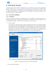
Figure 2–7. System Console Output
15. You can change the value written into the RAM by changing the value given in the
fill_memory routine in the set_memory_and_run_checksum.tcl file. Save the
Tcl file after editing and rerun the command. (Because the system command uses
master_write_32, if you use values that are less than 32 bits, they are filled with
leading 0s.)
Nios II Processor Example
In this example you program the Nios II processor on your board to run the count
binary software example that is included in the Nios II installation. This is a simple
program that, using an 8-bit variable, repeatedly counts from 0 to 0xFF. The output of
this variable is displayed on the LEDs and the seven-segment display on your board.
After programming the Nios II processor from the System Console, you use the
System Console processor commands to start and stop the processor.
To run this example, complete the following steps:
1. Copy the standard directory for your development board to a new location.
(Altera recommends that you use a separate directory structure for each project.)
This project uses C:\Count_binary\standard\
2. Open the Quartus II project file for your board, <board_version>_standard.qpf.
© November 2009
Altera Corporation
System Console User Guide
2–8
Chapter 2: System Console Examples
Nios II Processor Example
3. On the Tools menu, click SOPC Builder.
4. In a Nios II command shell, change to the directory of your new project.
5. To program your board, type the following command in a Nios II command shell:
nios2-configure-sof <board_version>_standard.sof r
6. In your Nios II command shell, type the following:
cd software_examples/app/count_binary r
7. To build the executable and linkable format (ELF) file (.elf) for this application,
type the following:
$ ./create-this-app r
f
For more information about creating Nios II applications, refer to the Using the Nios II
Software Build Tools chapter in the Nios II Software Developer’s Handbook.
8. Download the .elf file to your board by typing the following:
$ nios2-download -g count_binary.elf r
The seven-segment display and LEDs on your board provides a new light show.
9. Start the System Console by typing system-console in your Nios II command
shell.
10. Set the processor service path to the Nios II processor by typing the following
command:
set niosii_proc [lindex [get_service_paths processor] 0] r
11. Set the master service path to the Nios II processor by typing the following
command:
set niosii_master [lindex [get_service_paths master] 0] r
12. Open both services by typing the following commands:
open_service processor $niosii_proc r
open_service master $niosii_master r
13. Stop the processor by typing the following command:
processor_stop $niosii_proc r
The LEDs and seven-segment display on your board freezes.
14. Start the processor by typing the following command:
processor_run $niosii_proc r
The LEDs and seven-segment display on your board resume their previous
activity.
15. Stop the processor by typing the following command:
processor_stop $niosii_proc r
16. Close the services by typing the following command:
close_service master $niosii_master r
close_service processor $niosii_proc r
The processor_step, processor_set_register and
processor_get_register provide additional control over the Nios II processor.
System Console User Guide
© November 2009 Altera Corporation
Additional Information
Revision History
The table below displays the revision history for the chapters in this User Guide.
Date
Version
Changes Made
November 2009
1.3
■
Added the design plugin commands.
March 2009
1.2
■
Added sld_lock and sld_unlock commands
November 2008
1.1
■
Added device service type commands.
■
Expanded section explaining the system requirements for accessing the System Console.
■
May 2008
1.0
Added Figure 1–1 showing System Console connectivity.
Initial Release.
How to Contact Altera
For the most up-to-date information about Altera® products, see the following table.
Contact
Contact Method
Address
Technical support
Website
www.altera.com/support
Technical training
Website
www.altera.com/training
Email
[email protected]
Altera literature services
Email
[email protected]
Non-technical support (General)
Email
[email protected]
(Software Licensing)
Email
[email protected]
Note:
(1) You can also contact your local Altera sales office or sales representative.
Typographic Conventions
The following table shows the typographic conventions that this document uses.
Visual Cue
Meaning
Bold Type with Initial Capital
Letters
Indicates command names, dialog box titles, dialog box options, and other GUI
labels. For example, Save As dialog box.
bold type
Indicates directory names, project names, disk drive names, file names, file name
extensions, and software utility names. For example, \qdesigns directory, d: drive,
and chiptrip.gdf file.
Italic Type with Initial Capital Letters
Indicates document titles. For example, AN 519: Stratix IV Design Guidelines.
Italic type
Indicates variables. For example, n + 1.
Variable names are enclosed in angle brackets (< >). For example, <file name> and
<project name>.pof file.
© November 2009
Altera Corporation
System Console User Guide
Info–2
Additional Information
Typographic Conventions
Visual Cue
Meaning
Initial Capital Letters
Indicates keyboard keys and menu names. For example, Delete key and the Options
menu.
“Subheading Title”
Quotation marks indicate references to sections within a document and titles of
Quartus II Help topics. For example, “Typographic Conventions.”
Courier type
Indicates signal, port, register, bit, block, and primitive names. For example, data1,
tdi, and input. Active-low signals are denoted by suffix n. For example,
resetn.
Indicates command line commands and anything that must be typed exactly as it
appears. For example, c:\qdesigns\tutorial\chiptrip.gdf.
Also indicates sections of an actual file, such as a Report File, references to parts of
files (for example, the AHDL keyword SUBDESIGN), and logic function names (for
example, TRI).
1., 2., 3., and
a., b., c., and so on.
Numbered steps indicate a list of items when the sequence of the items is important,
such as the steps listed in a procedure.
■ ■
Bullets indicate a list of items when the sequence of the items is not important.
1
The hand points to information that requires special attention.
c
A caution calls attention to a condition or possible situation that can damage or
destroy the product or your work.
w
A warning calls attention to a condition or possible situation that can cause you
injury.
r
The angled arrow instructs you to press Enter.
f
The feet direct you to more information about a particular topic.
System Console User Guide
© November 2009 Altera Corporation