1
TUM-LS6
A. FPGA Basics Manuals
In this practical course, Field-Programmable Gate Array (FPGA) is used as the experimental
platform, which means to creation of a hardware description for the FPGA and writing software
for the created hardware. For experiments, toolchain from Altera Corporation is chosen, which
are Quartus II for hardware development and the Nios2SBT for software development. The
tutorial is specific for Altera toolchain.
A.1. Tool Chain Installation
A.1.1. Installation
Please note that this installation description applies to installing the Altera Design Suite v12
on Windows7 64bit only. To install the toolchain, one can either use the Altera Installer or our
pre-downloaded package. Details of the two approaches are show below:
• Altera Installer:
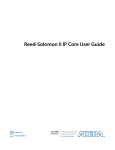
To install all the required software, Altera Corporation provides a free download package
on its website, called “Altera Design Suite (Altera Installer)”. This is an installer package,
which downloads all selected installation components during the installation process from
the Internet. To start the installation, execute the installer package as an administrative
user (right-click and select “run as administrator”). This step is very important, as the
USB-Blaster will not work if you install the software as a low-privileged user.
Figure 1: Component selection in the Altera Installer
• Pre-downloaded package:
156
TUM-LS6
Go to directory tools/altera-installation, double click file
12.1sp1 243 quartus free windows.exe,
the installation will start as previously described.
Altera offers a paid (Quartus II Subscription Edition) and a free (Quartus II Web Edition)
version of its Quartus development suite. The free version includes most of the features for
beginners or even professionals. One striking difference is the missing Intellectual Property (IP)
license files for several more complex components. These components, which are not fully licensed to free edition users include, but are not limited to NiosII/s or NiosII/f processors (the
NiosII/e processor does not require a license), the DDR Random Access Memory (RAM) controller or the Triple Speed Ethernet (TSE) Ethernet Media Access Control (MAC) component.
A.1.2. Tips
1. If running Quartus II v12.0 on a 64bit machine, one might still have difficulties finding
the USB Blaster hardware in the Programmer tool. Altera does not ship the 64bit JTAGServer with the QuartusII Web-Edition. To resolve this issue, install the standalone Programmer Software from https://www.altera.com/download/software/prog-software,
which contains a 64bit Programmer and Joint Test Action Group (JTAG)-Server (update:
as of Quartus II v12.1, there is no need to separately install the standalone Programmer).
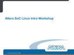
2. The installation package does include the driver for the USB Blaster device. The device
driver, however, does not automatically installed during the installation of the Altera
toolchain. To install the device drive, go to the ”Device Manager” and reinstall the drive,
as shown in Fig. 2. When reinstalling the driver, locate the driver at directory:
c:\altera\12.1sp1\quartus\drivers\usb blaster.
Figure 2: Altera USB Blaster
157
TUM-LS6
A.2. Hello-World SoC
A.2.1. Prerequisite
• Successfully finish Section A.1.
• The Hello-World package, which includes the hardware description files, e.g., .sof and
.sopcinfo, and the software source code.
A.2.2. Download Hardware Design to FPGA
Now that you have created a hardware description for your FPGA and have successfully generated/compiled it, you can proceed to program your design. Programming your hardware design
onto the FPGA can be done from the console or by using the Programmer User Interface (UI).
Programming the FPGA chip will keep the hardware description in the chip until the next
programming or power loss. This means that the chip has to be programmed again each time
the development board is turned off. To avoid reprogramming upon each power cycle, the
FPGA chip can be set to an automatic programming mode. In this mode, the FPGA will take
the hardware description from a flash memory and program itself upon start. But there is a
restriction to this automatic programming mode: It can only be used, if all the components used
in the current hardware design are properly licensed (e.g., the TSE Ethernet MAC component
is not licensed in Quartus II Web Edition). See section ?? for a short summary of the differences
between Quartus versions.
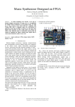
Figure 3: Main window of Programmer
One can start the Programmer manually or even fire it up from your Quartus instance (see
figure 3 for a screenshot of the Programmer main window). To do so, open your hardware design
project and select “Tools/Programmer” from the menu bar. If you start Programmer from
Quartus, the hardware design you want to program should already be preselected. Otherwise,
you can use the Add File... button to add your .sof of .pof file. If your FPGA chip is not
158
TUM-LS6
selected yet, you can use the Add Device... button to select your FPGA chip. Make sure to
select the correct chip number, otherwise you risk damaging your hardware.
Figure 4: Time limitation warning of Programmer
If you are using a non-licensed component in your hardware design, you can still use that
component, but you can only use it while your FPGA is connected to your Computer running
Programmer. A message will appear, which reminds you of that situation (the message might
look like figure 4).
Figure 5: Hardware setup window of Programmer
Now you need to set your USB Blaster connection to the FPGA chip. Simply click the
Hardware Setup... button and a window like 5 will pop up. If you are using USB Blaster for
programming (on DE2-115 boards, you are using USB Blaster ), your USB Blaster will show up
in the list of Available hardware items. Select it from the Currently selected hardware dropdown
list, close the Hardware Setup window and you should be ready to start programming. The Start
button should be enabled, if you have added a .sof of .pof file, if you have selected a FPGA
device and if your USB Blaster is selected. Start programming by clicking that button. The
progress bar should show Success after programming finished successfully. This means that your
hardware design was programmed onto the FPGA chip. If you are using non-licensed (timelimited) components, a popup window will appear after successful programming (see figure 4).
159
TUM-LS6
Leave this window open and keep the FPGA chip connected to your computer until you have
finished using your hardware design.
Sometimes you could have issues with your USB Blaster hardware detection. If your USB
Blaster is not selected (from your previous programming), try to select it again in the Hardware
Setup... window. If it does not show up in the list of Available hardware items, check your
physical connection to your development board. Make sure the USB cable is connected properly
to your computer and the FPGA hardware. Also make sure, that your FPGA hardware is
connected to a power source and the power switch is turned on. If the USB programmer is still
not shown in the list, close the hardware selection window and open it again (you may need
to repeat this procedure several times). In fact, simply retrying the failed operation helps in
many cases for the Programmer (not only the issues, which are listed here). Another way to get
the Programmer working is to select Auto Detect or turning your development board off and
on again. If your USB Blaster did never show up in the list of available hardware components,
there might be a driver issue on your system. This could be, because you ran the installation
process as a non-privileged user. Also make sure, that your USB Blaster is listed in Device
Manager (on Windows machines).
Once the download is complete, the Progress bar of Programmer window, located at the
top-right of Fig. 3, the will indicated 100% (Successful).
A.2.3. Setting up the BSP
After finishing all hardware related aspects of this introduction into the DE2-115 FPGA, we
are ready to start working on the software. Typically, NiosII applications are developed using the Nios2SBT (NiosII Software Build Tools), a modified version of the eclipse Integrated
Development Environment (IDE). NiosII applications usually consist of two parts:
• The NiosII Board Support Package (BSP), a software library and runtime environment,
which is customized to a Central Processing Unit (CPU) and a hardware design.
• The NiosII application, which is the program implementing the functionality required by
the user and relying on functions provided by the BSP
Start the Nios2SBT and select a workspace if you have not done so yet. To create a new
NiosII BSP, select “File/New/Nios II Board Support Package”(Fig. 6), which will open the
BSP creation wizard (see Fig. 7). Choose a name for the BSP project and select the path to
the .sopcinfo file, which has been generated for your NiosII system. The .sopcfile should be
located in the QuartusII project folder. You can change the location of the BSP (be default, it
is saved in a subfolder of the QuartusII project folder). Select the CPU for which the BSP shall
be created (in case you have more than one CPU in your NiosII system). A BSP can only be
generated for one CPU at once. If you have more CPUs in one hardware design, you have to
create a BSP for each processor. Confirm your selection by pressing the Finish button of the
BSP creation wizard. Your BSP project will appear in the Project Explorer of the Nios2SBT.
A.2.4. Setting up the application project
Now we are creating the actual NiosII application project, which uses the BSP, that we just
created. Choose “File/New/Nios II Application” (Fig. 8) to open the Nios II Application wizard
(see figure 9). Enter a name for your application project and select the BSP for your project
(the BSP that you created in section A.2.3). Create the project by selecting the Finish button.
The project appears in the Project Explorer, as shown in Fig. 10. Basically, we just create two
projects, one for the BSP and the other for the application.
Note that although the application project has been created, there is no application-specific
source code within the project. The next step is to create the application source code. To input
160
TUM-LS6
Figure 6: BSP creation wizard Location
Figure 7: BSP creation wizard
161
TUM-LS6
Figure 8: Application creation wizard from Eclipse menu
Figure 9: Application creation wizard
162
TUM-LS6
Figure 10: System with BSP and application projects
the application source code into the project, there are two approaches, i.e., using the source-code
wizard and manual creation.
Figure 11: New file wizard
163
TUM-LS6
Source-Code Wizard
To add a new source file to the application project, right-click on the application project and
select “New/Source File”. In the New Source File window (see figure 11), enter a name for the
Source File and click Finish to create your file. Every project has to contain a main function,
which is the entry point to your application. Start by creating this function and adding code
to it. Listing 1 shows how a basic main function could look like. It demonstrates the output of
text to the console by using:
1
printf ( ‘ ‘ Hello from Nios II !\ n ’ ’) ;
and controls the LEDs, that we connected via a Parallel I/O (PIO) component by using:
1
I O W R _ A L T E R A _ A V A L O N _ P I O _ D A T A ( PIO_LED_BASE , count & 0 x01 ) ;
Congratulations, you created your first NiosII software application.
1
2
3
# include < stdio .h >
# include < system .h >
# include " al te ra _av al on _pi o_ re gs . h "
4
5
6
7
8
9
10
11
12
13
14
15
16
17
18
int main () {
printf ( " Hello from Nios II !\ n " ) ;
int count = 0;
int delay ;
while (1) {
I O W R _ A L T E R A _ A V A L O N _ P I O _ D A T A ( LED_PIO_BASE , count & 0 x01 ) ;
delay = 0;
while ( delay < 2000000) {
delay ++;
}
count ++;
}
return 0;
}
Listing 1: Example implementation of main function
Manual Creation
In the case that there is existing source code, one convenient way is to manually import the
source files into the project. Basically, one can just copy the existing source files directly to
the directory where the generated project is located. Then use the reflash key to generate the
corresponding Makefile, as shown in Fig. 12.
A.2.5. Executing NiosII projects on the target hardware
You can execute your NiosII project from the Nios2SBT. To execute the application, right-click
on the application project in the Project Explorer and choose “Run As/Nios II Hardware”. This
will compile your application, create a downloadable image, download the software image and
execute it on the target hardware. Before executing, please make sure that you programmed
the target hardware with the correct hardware design (see section ??).
Another option is to debug your application. To start debugging, right-click the project and
select “Debug As/Nios II Hardware”. This will execute the same steps as running the software
and additionally start Nios2SBT’s debugger.
If a window similar to figure 17 appears, your Target Connection setup may be incorrect. To
setup the target connection, open the Target Connection tab and click the Refresh Connections
button. Select a Processor to execute your target on and a Byte Stream Device, through which
164
TUM-LS6
Figure 12: Reflesh the application project to import source code
Figure 13: Compile the application
text output will be transferred (see 18). Confirm your selection with Apply and start debugging
the software with Debug.
This finishes the tutorial on how to run your first NiosII Application.
165
TUM-LS6
Figure 14: The result of the application compilation
Figure 15: Run the application on the FPGA
166
TUM-LS6
Figure 16: The result of the application execution
Figure 17: Error indicating wrong target connection path
A.2.6. Tips
• Enable the enable small driver option, click the Generate button, and then the Exit button.
• No white space is allowed for all the names of the files and projects.
167
TUM-LS6
Figure 18: Choosing the target connection
Figure 19: BSP editor
A.3. Self-Booting
This section describes how to create a self-booting design such that the FPGA board can boot
up the designed system from flash memory once power up.
168
TUM-LS6
Figure 20: Edit the bsp options to enable small driver
A.3.1. Hardware Support
First of all, the designed System-on-a-Chip (SoC) needs hardware support for writing the EPCS
flash. In the case that the corresponding hardware is not included in the design, this section
guides you to integrate the hardware. Detailed steps are shown in the following figures.
Figure 21: Open the design from the SOPC builder. From the ”Component Library” at the top
left of the figure, search EPCS component. Select the component and ”Add” to the
design (the red arrow).
169
TUM-LS6
Figure 22: After clicking the ”Add” button, this figure will show up. Just click the ”Finish”
button.
After the operation at Fig. 22, one will go back to the main panel of the SOPC builder, similar
to Fig. 21. Now double click the nios entry, which lead to Fig. 23. One needs to change the
”Reset Vector” of the Nios processor to the EPCS controller.
After the generation, there should be four extra pins in the design, i.e.,data0, dclk, sce, sdo.
These are dual-purpose pins. From the menu ”Assignment->device-> device and pin options”
(Fig. 26) to see if these pins are used as regular I/O. If not, change them into regular I/O
(Fig. 27). Otherwise, there will be synthesize errors.
If it is not possible to change them in the GUI, please add following tcl script into project
setting file with extension of .qsf file.
1
2
3
4
5
6
7
8
s e t _ g l o bal_ assig nmen t
‘‘ USE AS REGULAR IO ’ ’
s e t _ g l o bal_ assig nmen t
AS REGULAR IO ’ ’
s e t _ g l o bal_ assig nmen t
AS REGULAR IO ’ ’
s e t _ g l o bal_ assig nmen t
REGULAR IO ’ ’
- name R E S E R V E D _ F L A S H _ N C E _ A F T E R _ C O N F I G U R A T I O N
- name R E S E R V E D _ D A T A 0 _ A F T E R _ C O N F I G U R A T I O N ‘‘ USE
- name R E S E R V E D _ D A T A 1 _ A F T E R _ C O N F I G U R A T I O N ‘‘ USE
- name R E S E R V E D _ D C L K _ A F T E R _ C O N F I G U R A T I O N ‘‘ USE AS
Listing 2: Pin Options
The next step is for pin assignment, i.e., to assign the signals of the Nios core to physical pins
of the chip. Similar to defining the pin options, one can just copy the code in Listing ?? to the
.qsf file. The result of this operation is shown in Fig. 28.
1
2
3
s e t _ l o c a t io n_ a ss i gn me n t PIN_H2 - to EPCS_DATA0
s e t _ i n s t a nc e_ a ss i gn me n t - name IO_STANDARD " 3.3 - V LVTTL " - to EPCS_DATA0
s e t _ l o c a t io n_ a ss i gn me n t PIN_H1 - to EPCS_DCLK
170
TUM-LS6
Figure 23: Changing the reset to EPCS controller.
Figure 24: Regenerate the design.
4
5
6
7
8
s e t _ i n s t a nc e_ a ss i gn me n t
s e t _ l o c a t io n_ a ss i gn me n t
s e t _ i n s t a nc e_ a ss i gn me n t
s e t _ l o c a t io n_ a ss i gn me n t
s e t _ i n s t a nc e_ a ss i gn me n t
- name IO_STANDARD " 3.3 - V LVTTL " - to EPCS_DCLK
PIN_D2 - to EPCS_NCSO
- name IO_STANDARD " 3.3 - V LVTTL " - to EPCS_NCSO
PIN_C1 - to EPCS_ASDO
- name IO_STANDARD " 3.3 - V LVTTL " - to EPCS_ASDO
Listing 3: Pin Assignment
171
TUM-LS6
Figure 25: Indication of a successful generate.
Figure 26: Pin options.
172
TUM-LS6
Figure 27: Pin options.
Figure 28: Pin options.
173
TUM-LS6
Figure 29: A view of the overall pin assignment of the design.
174
TUM-LS6
A.3.2. Writing the EPCS flash
Figure 30: Start the EPCS flash programmer from the NIOS II Eclipse IDE.
Figure 31: First set a new download.
175
TUM-LS6
Figure 32: Start the EPCS flash programmer from the NIOS II Eclipse IDE.
Figure 33: Select the hardware and software images to download.
176
TUM-LS6
Figure 34: The GUI after selecting the images.
177