1
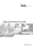
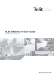
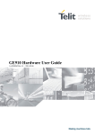
SPECIFICATIONS SUBJECT TO CHANGE WITHOUT NOTICE Notice While reasonable efforts have been made to assure the accuracy of this document, Telit assumes no liability resulting from any inaccuracies or omissions in this document, or from use of the information obtained herein. The information in this document has been carefully checked and is believed to be entirely reliable. However, no responsibility is assumed for inaccuracies or omissions. Telit reserves the right to make changes to any products described herein and reserves the right to revise this document and to make changes from time to time in content hereof with no obligation to notify any person of revisions or changes. Telit does not assume any liability arising out of the application or use of any product, software, or circuit described herein; neither does it convey license under its patent rights or the rights of others. It is possible that this publication may contain references to, or information about Telit products (machines and programs), programming, or services that are not announced in your country. Such references or information must not be construed to mean that Telit intends to announce such Telit products, programming, or services in your country. Copyrights This instruction manual and the Telit products described in this instruction manual may be, include or describe copyrighted Telit material, such as computer programs stored in semiconductor memories or other media. Laws in the Italy and other countries preserve for Telit and its licensors certain exclusive rights for copyrighted material, including the exclusive right to copy, reproduce in any form, distribute and make derivative works of the copyrighted material. Accordingly, any copyrighted material of Telit and its licensors contained herein or in the Telit products described in this instruction manual may not be copied, reproduced, distributed, merged or modified in any manner without the express written permission of Telit. Furthermore, the purchase of Telit products shall not be deemed to grant either directly or by implication, estoppel, or otherwise, any license under the copyrights, patents or patent applications of Telit, as arises by operation of law in the sale of a product. Computer Software Copyrights The Telit and 3rd Party supplied Software (SW) products described in this instruction manual may include copyrighted Telit and other 3rd Party supplied computer programs stored in semiconductor memories or other media. Laws in the Italy and other countries preserve for Telit and other 3rd Party supplied SW certain exclusive rights for copyrighted computer programs, including the exclusive right to copy or reproduce in any form the copyrighted computer program. Accordingly, any copyrighted Telit or other 3rd Party supplied SW computer programs contained in the Telit products described in this instruction manual may not be copied (reverse engineered) or reproduced in any manner without the express written permission of Telit or the 3rd Party SW supplier. Furthermore, the purchase of Telit products shall not be deemed to grant either directly or by implication, estoppel, or otherwise, any license under the copyrights, patents or patent applications of Telit or other 3rd Party supplied SW, except for the normal non-exclusive, royalty free license to use that arises by operation of law in the sale of a product. Usage and Disclosure Restrictions License Agreements The software described in this document is the property of Telit and its licensors. It is furnished by express license agreement only and may be used only in accordance with the terms of such an agreement. Copyrighted Materials Software and documentation are copyrighted materials. Making unauthorized copies is prohibited by law. No part of the software or documentation may be reproduced, transmitted, transcribed, stored in a retrieval system, or translated into any language or computer language, in any form or by any means, without prior written permission of Telit High Risk Materials Components, units, or third-party products used in the product described herein are NOT fault-tolerant and are NOT designed, manufactured, or intended for use as on-line control equipment in the following hazardous environments requiring fail-safe controls: the operation of Nuclear Facilities, Aircraft Navigation or Aircraft Communication Systems, Air Traffic Control, Life Support, or Weapons Systems (High Risk Activities"). Telit and its supplier(s) specifically disclaim any expressed or implied warranty of fitness for such High Risk Activities. Trademarks TELIT and the Stylized T Logo are registered in Trademark Office. All other product or service names are the property of their respective owners. Copyright © Telit Communications S.p.A. 2014 Contents [email protected] [email protected] [email protected] [email protected] Figure 1 Pad Signal I/O Function Note Type E7 EAR- AO Earphone signal output, phase - Audio Audio D7 EAR+ AO Earphone signal output, phase + Audio G7 MIC- AI Mic. signal input; phase- Audio F7 MIC+ AI Mic. signal input; phase+ Audio F6 AGND - Analog Ground Power SIM card interface C7 SIMVCC - External SIM signal – Power supply for the SIM 1,8 / 3V 1,8 / 3V B7 SIMRST O External SIM signal – Reset A7 SIMCLK O External SIM signal – Clock A6 X All GPI0 can be program med SIMIO I/O External SIM signal – Data I/O SIMIN I Presence SIM input 1,8 / 3V 4.7k Pull up 1,8 / 3V CMOS 1.8V Trace C2 RXD_AUX I Auxiliary UART (RX Data) CMOS 1.8V C1 TXD_AUX O Auxiliary UART (TX Data) CMOS 1.8V A4 C103/TXD I Prog. / Data + HW Flow Control Output for Data carrier detect signal (DCD) to DTE / GP output Output for Ring indicator signal (RI) to DTE / GP output Output for Data set ready signal (DSR) to DTE / GP output Input for Data terminal ready signal (DTR) from DTE / GP input Input for Request to send signal (RTS) from DTE / GP input Output for Clear to send signal (CTS) to DTE / GP output Serial data input (TXD) from DTE A5 C104/RXD O Serial data output to DTE F4 ADC_IN AI Analog/Digital converter input A/D E4 DAC_OUT AO Digital/Analog converter output D/A B2 C109/DCD/GPO O B3 C125/RING/GPO O A3 C107/DSR/GPO O A2 C108/DTR/GPI I A1 C105/RTS/GPI I B1 C106/CTS/GPO O CMOS 1.8V CMOS 1.8V CMOS 1.8V CMOS 1.8V CMOS 1.8V CMOS 1.8V CMOS 1.8V CMOS 1.8V DAC and ADC Miscellaneous Functions F5 VRTC AO VRTC Backup 2.3V Power Pad Signal I/O Function G4 RESET* I G6 V_AUX / PWRMON O G2 Antenna I/O Reset input 1.8V stabilized output Imax=100mA / Power ON monitor Antenna pad – 50 Ω GPIO GPIO01 Configurable GPIO / Digital Audio Interface (WA0) GPIO02 I/O pin / Jammer Detect Report / Digital Audio Interface (RX) GPIO03 GPIO I/O pin / Digital Audio Interface (TX) GPIO04 Configurable GPIO / TX Disable input / Digital Audio Interface (CLK) GPIO05 Configurable GPIO / Transmitter ON monitor GPIO06 Configurable GPIO / ALARM GPIO07 Configurable GPIO / Digital Audio Interface (CLK) Power Supply Note Type CMOS 1.8V Power Out 1.8V RF C5 GPIO_01 / DVI_WA0 I/O CMOS 1.8V C6 GPIO_02 / JDR / DVI_RX I/O D6 GPIO_03 / DVI_TX I/O D5 GPIO_04 / TX Disable / DVI_CLK I/O B5 GPIO_05 / RFTXMON I/O B4 GPIO_06 / ALARM / BUZZER I/O C4 GPIO_07 / STAT_LED I/O E2 VBATT - Main power supply (Baseband) E1 VBATT_PA - Main power supply (Radio PA) Power F6 AGND - AF Signal Ground (see audio section) AF Signal D1 GND - Ground Power F1 GND - Ground Power G1 GND - Ground Power D2 GND - Ground Power CMOS 1.8V CMOS 1.8V CMOS 1.8V CMOS 1.8V CMOS 1.8V CMOS 1.8V Power F2 GND - Ground Power C3 GND - Ground Power E3 GND - Ground Power F3 GND - Ground Power G3 GND - Ground Power RESERVED D3 - D4 - E5 - G5 - B6 - E6 - Pin E2, E1 D1, F1, G1, D2, F2, C2, E3, F3, G3 F6 A4 A5 A1 G6 G4 C1 C2 signal VBATT & VBATT_PA GND AGND TXD RXD RTS V_AUX / PWRMON RESET* TXD_AUX RXD_AUX A B C D E F G 1 C105/RTS C106/CTS TXD_AUX GND VABTT_PA GND GND 2 C108/DTR C109/DCD RXD_AUX GND VABTT GND ANT 3 C107/DSR C125/RING GND RESERVED GND GND GND 4 C103/TXD GPIO_06/ ALRM/ BUZZER GPIO_07/ STAT_LED RESERVED DAC_OUT ADC_IN RESET* 5 C104/RXD GPIO_05/ RFTXMON GPIO_01/ DVI_WAO GPIO_04/ TX_DIS/ DVI_CLK RESERVED VRTC RESERVED 6 SIMIO RESERVED GPIO_02/ JDR/ DVI_RX GPIO_03/ DVI_TX RESERVED AGND V_AUX/ PWRMON 7 SIMCLK SIMRST SIMVCC EAR+ EAR- MIC+ MIC- AUDIO SIM MISCELLANOUS SERIAL GPIO ANTENNA RESERVED/FU POWER GND Modem ON Proc. PWR supply = ON? N Y Delay 300mS Enter AT<CR> Y PWMON = ON? Y AT answer in 1second ? N Delay 1s - 5s for Low Voltage Operating PWMON = ON? N N Modem Reset Proc. Y Delay 1s Start AT CMD. AT init sequence. Start AT CMD. Delay 300mS Enter AT<CR> Y AT answer in 1second? N Disconnect PWR supply Modem ON Proc. AT init sequence. Modem OFF Proc. AT#SYSHALT 10s timeout Disconnect PWR supply Delay 1.5s Modem ON Proc. Modem Reset Proc. Reset = LOW Delay 200ms Reset = HIGH Delay 1s Start AT CMD. POWER SUPPLY Nominal Supply Voltage Normal Operating Voltage Range Extended Operating Voltage Range 3.8 V 3.40 V÷ 4.20 V 3.10 V÷ 4.50 V GE866-QUAD Mode Average (mA) SWITCHED OFF Switched Off Switched Off with AT#SYSHALT IDLE mode AT+CFUN=1 AT+CFUN=4 Typical 2uA max 20uA <500uA AT+CFUN=0 or =5 CSD TX and RX mode GSM900 CSD PL5 DCS1800 CSD PL0 GPRS (class 1) 1TX + 1RX GSM900 PL5 DCS1800 PL0 GPRS (class 10) 2TX + 3RX GSM900 PL5 DCS1800 PL0 Mode description Module power supplied only on VBATT_PA pin, the VBATT pin is not power supplied. Module power supplied on VBATT_PA pin and VBATT pin, the command AT#SYSHALT is applied. 9 9 1.7 1.5 1.3 0,9 Normal mode: full functionality of the module Disabled TX and RX; module is not registered on the network Paging Multiframe 2 Paging Multiframe 3 Paging Multiframe 4 Paging Multiframe 9 200 150 GSM VOICE CALL 200 140 GPRS Sending data mode 330 250 GPRS Sending data mode μ μ μ ANTENNA REQUIREMENTS Frequency range Gain Impedance Input power VSWR absolute max VSWR recommended 824-894 MHz GSM850 band 880-960 MHz GSM900 band 1710-1885MHz DCS1800 band 1850-1990MHz PCS1900 band 1.4dBi @ GSM900 and 3dBi @ DCS1800 1.4dBi @ GSM850 and 3dBi @ PCS1900 50 Ohm >2W ≤ 10:1 (limit to avoid permanent damage) ≤ 2:1 (limit to fulfill all regulatory requirements) ANTENNA LINE ON PCB REQUIREMENTS 50 ohm Impedance 0,3 dB Max Attenuation No coupling with other signals allowed Cold End (Ground Plane) of antenna shall be equipotential to the GE866-QUAD ground pins ε Ω Ω Ω Ω Parameter Input level on any digital pin (CMOS 1.8) when on Min -0.3V Max +2.1V Level Min Max Input high level 1.3V 1.9V Input low level Output high level 0V 1.6V 0V 0.35V 1.9V 0.2V Output low level Level Typical Output Current 1mA Input Current 1uA Signal Function I/O pin RESET* Phone reset I G4 Signal Min Max RESET* Input high 1.8V(NOTE1) 2.1V RESET* Input low 0V 0.2V Parameter Input level on any digital pad when on Input voltage on analog pads when on Min -0.3V Max +2.1V -0.3V +2.1V Level Input high level VIH Min 1.5V Max 1.9V 0V 0.35V Input low level VIL Output high level VOH Output low level VOL 1.6V 0V RS232 Pin Number Signal GE866-QUAD Pad Number Name 1 DCD - dcd_uart B2 2 RXD - tx_uart A5 3 TXD - rx_uart A4 4 DTR - dtr_uart A2 5 GND D1, F1, G1, D2, F2, C2, E3, F3, G3 Ground 6 DSR - dsr_uart A3 Data Set Ready 7 RTS - rts_uart A1 Request to Send 8 CTS - cts_uart B1 Clear to Send 9 RI - ri_uart B3 Ring Indicator 1.9V 0.2V Usage Output from the GE866-QUAD that indicates the carrier presence Transmit line *see Output transmit line of GE866Note QUAD UART Input receive of the GE866-QUAD Receive line *see Note UART Input to the GE866-QUAD that Data Terminal Ready controls the DTE READY condition Data Carrier Detect Ground Output from the GE866-QUAD that indicates the module is ready Input to the GE866-QUAD that controls the Hardware flow control Output from the GE866-QUAD that controls the Hardware flow control Output from the GE866-QUAD that indicates the incoming call condition EAR+ + DAC OUTPUT EAR- TELIT MODULE EAR+ + DAC OUTPUT - EAR- GND TELIT MODULE + DAC OUTPUT - TELIT MODULE EAR+ EAR- GND HiZ CIRCUITRY Microphone/Line-in path Line Type Differential ≥ 100nF Coupling capacitor 50kΩ Differential input resistance Levels To have 0 dBfs @1KHz (*) Differential input voltage MIC Gain = 0dB 290mVrms MIC Gain = +6dB 145mVrms MIC Gain = +12dB 72mVrms MIC Gain = +18dB 36mVrms MIC Gain = +24dB 18mVrms MIC Gain = +30dB 9mVrms MIC Gain = +36dB 4.5mVrms MIC Gain = +42dB 2.25mVrms EAR/Line-out Output Direct connection (VDC=1.7÷2.1V) Differential line coupling output load resistance ≥8Ω signal bandwidth max. differential output voltage 250÷3400Hz (@ -3dB with default filter) 1120 mVpp @3.14dBm0 (*) differential output voltage 550mVrms @0dBm0 (*) volume increment 2dB per step volume steps 0..10 Pin Signal I/O Function C5 GPIO_01 I/O Configurable GPIO C6 GPIO_02 I/O Configurable GPIO D6 GPIO_03 I/O Configurable GPIO D5 GPIO_04 I/O Configurable GPIO B5 GPIO_05 I/O Configurable GPIO B4 GPIO_06 I/O Configurable GPIO C4 GPIO_07 I/O Configurable GPIO Type CMOS 1.8V CMOS 1.8V CMOS 1.8V CMOS 1.8V CMOS 1.8V CMOS 1.8V CMOS 1.8V Input / output current Default State ON_OFF state State during Reset Note 1uA/1mA INPUT 0 0 Alternate function DVI_WA0 1uA/1mA INPUT 0 0 Alternate function JDR and DVI_RX 1uA/1mA INPUT 0 0 1uA/1mA INPUT 0 0 1uA/1mA INPUT 0 0 1uA/1mA INPUT 0 0 1uA/1mA INPUT 0 0 Alternate function DVI_TX Alternate function TX Disable and DVI_TX Alternate function RFTXMON Alternate function ALARM / BUZZER Alternate function STAT_LED Pin Signal I/O Function B2 GPO_A O Configurable GPO B3 GPO_B O Configurable GPO A3 GPO_C O Configurable GPO A2 GPI_E I Configurable GPI A1 GPI_F I Configurable GPI B1 GPO_D O Configurable GPO Type CMOS 1.8V CMOS 1.8V CMOS 1.8V CMOS 1.8V CMOS 1.8V CMOS 1.8V Input / output current Default State ON_OFF state State during Reset 1uA/1mA INPUT 0 0 1uA/1mA INPUT 0 0 1uA/1mA INPUT 0 0 1uA/1mA INPUT 0 0 1uA/1mA INPUT 0 0 1uA/1mA INPUT 0 0 Parameter Input level on any digital pin (CMOS 1.8) when on Min -0.3V Max +2.1V Level Min Max Input high level 1.5V 1.9V Input low level Output high level 0V 1.6V 0V 0.35V 1.9V 0.2V Output low level Level Typical Output Current 1mA Input Current 1uA Note Alternate function C109/DCD Alternate function C125/RING Alternate function C107/DSR Alternate function C108/DTR Alternate function C105/RTS Alternate function C106/CTS TR2 SMBT2907A +V buzzer R1 4,7K D1 D1N4148 R2 1K GPIO7 TR1 BCR141W C1 33pF + - ↑ ↓ ↓ ↑ LED status Permanently off Fast blinking (Period 1s, Ton 0,5s) Slow blinking (Period 3s, Ton 0,3s) Permanently on Device Status Device off Net search / Not registered / turning off Registered full service a call is active Voltage range (filtered) Range Min 0 0 Max 1.8 1023 Units Volt Steps Min Input Voltage range AD conversion Resolution 0 - Max 1.2 10 >1 Units Volt bits mV Surface finishing Ni/Au for all solder pads Dimensions in mm NOTE: . ≥ Copper Pad Solder Mask PCB SMD (Solder Mask Defined) NSMD (Non Solder Mask Defined) Inhibit area for micro-via Finish Layer thickness [µm] Properties NOTE: WARNING: . WARNING: These trays can withstand at the maximum temperature of 65° C. READ CAREFULLY Be sure the use of this product is allowed in the country and in the environment required. The use of this product may be dangerous and has to be avoided in the following areas: Where it can interfere with other electronic devices in environments such as hospitals, airports, aircrafts, etc. Where there is risk of explosion such as gasoline stations, oil refineries, etc. It is responsibility of the user to enforce the country regulation and the specific environment regulation. Do not disassemble the product; any mark of tampering will compromise the warranty validity. We recommend following the instructions of the hardware user guides for a correct wiring of the product. The product has to be supplied with a stabilized voltage source and the wiring has to be conforming to the security and fire prevention regulations. The product has to be handled with care, avoiding any contact with the pins because electrostatic discharges may damage the product itself. Same cautions have to be taken for the SIM, checking carefully the instruction for its use. Do not insert or remove the SIM when the product is in power saving mode. The system integrator is responsible of the functioning of the final product; therefore, care has to be taken to the external components of the module, as well as of any project or installation issue, because the risk of disturbing the GSM network or external devices or having impact on the security. Should there be any doubt, please refer to the technical documentation and the regulations in force. Every module has to be equipped with a proper antenna with specific characteristics. The antenna has to be installed with care in order to avoid any interference with other electronic devices and has to guarantee a minimum distance from the body (20 cm). In case of this requirement cannot be satisfied, the system integrator has to assess the final product against the SAR regulation. The European Community provides some Directives for the electronic equipments introduced on the market. All the relevant information’s are available on the European Community website: http://ec.europa.eu/enterprise/sectors/rtte/documents/ The text of the Directive 99/05 regarding telecommunication equipments is available, while the applicable Directives (Low Voltage and EMC) are available at: http://ec.europa.eu/enterprise/sectors/electrical/ Revision Rev. 0 Rev. 1 Date 2013-10-02 2014-02-07 Rev.2 Rev.3 2014-09-05 2014-09-10 Changes First issue Updated VRTC voltage, power consumption and packing system Updated Mechanical Dimensions Updated section 13 “Mounting the GE866 on your Board”