1
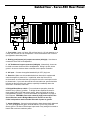
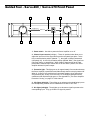
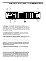
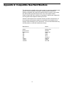
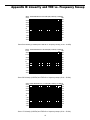
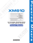
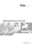
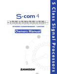
SERVO 170/260/550
S
T
E
R
E
O
AMPLIFIER
OWNERS MANUAL
®
Introduction 3
System Features 4
Guided Tour 5
Servo-550 Front Panel 5
Servo-550 Rear Panel 6
Servo-260 / Servo-170 Front Panel 7
Servo-260 / Servo-170 Rear Panel 8
Setting Up and Using the Servo Amplifier 9
Suggested Applications 10
Appendix A: Compatible Studio Nearfield Monitors 11
Appendix B:
Linearity and THD vs. Frequency Sweep 12
Appendix C: Power Output vs. THD 13
Appendix D:
The Servo Amplifier Protection Circuitry 14
Appendix E: Bridged Mono Mode 15
Specifications 16
Introduction
Congratulations on purchasing the Samson Servo Amplifier! Although designed
for easy operation, we suggest you first take some time to go through these
pages so you can fully understand how we’ve implemented a number of unique
features.
The Servo Amplifier is a stereo power amplifier which is optimized for use in
both professional and project recording studio environments as well as for live
performance. This manual covers three models, which differ primarily in terms
of the power they provide: the Servo-550, which delivers 275 watts of power per
channel (into 4 ohms); the Servo-260, which delivers 130 watts of power per
channel (into 4 ohms); and the Servo-170, which delivers 85 watts of power per
channel (into 4 ohms). In addition, the Servo-550 provides a mono bridging
switch and a binding post (banana jack) output connector. All Servo Amplifier
models can be used in a variety of applications, including powering studio
nearfield or performance stage monitors, providing amplification for small and
medium-sized public address systems, driving small and medium bi-amped and
tri-amped speaker systems, as an extension to a home hi-fi system, and as the
main amplifier in installations such as classrooms and corporate conference
rooms.
In these pages, you’ll find a detailed description of the many features of your
Servo Amplifier, as well as a guided tour through its front and rear panels,
step-by-step instructions for its setup and use, reference appendices, and full
specifications. You’ll also find a warranty card enclosed—please don’t forget to
fill it out and mail it in so that you can receive online technical support and so we
can send you updated information about these and other Samson products in
the future.
SPECIAL NOTE: Should your unit ever require servicing, a Return Authorization
number (RA) is necessary. Without this number, the unit will not be accepted.
Please call Samson at 1-800-372-6766 for a Return Authorization number prior
to shipping your unit. Please retain the original packing materials and, if
possible, return the unit in its original carton and packing materials.
3
System Features
The Samson Servo Amplifier utilizes the latest technology in professional power
amplifier design. Here are some of its main features:
• The Servo-550 model delivers 275 watts (into 4 ohms) of power per side.
The Servo-260 model delivers 130 watts (into 4 ohms) of power per side.
The Servo-170 model delivers 85 watts (into 4 ohms) of power per side.
• Optimized for usage in professional and project recording studios as well as
live performance, the Servo Amplifier boasts specifications (such as 0.03%
THD, S/N of 103 dB, crosstalk of 83 dB, and frequency response of 20 Hz to
50 kHz) that ensure ultra-clean sound quality in any environment.
• Unique bipolar circuit design that continuously keeps DC output during idling
at or near 0 volts (thus keeping idle speakers at their 0 point). This serves to
minimize heat overload problems by effectively preventing the Servo
Amplifier from applying power when unnecessary.
• Protection relay circuitry (linked to the DC offset circuitry) that prevents
“thumps” when powering on or off. This means that you can use the Servo
Amplifier with a single power strip into which a mixer or other audio devices
are connected, without danger of damage to connected speakers.
• The incorporation of high-current output power transistors that provide
power to spare.
• Front-panel Clip, Idle and Protection lights that show you at a glance the
status of the Servo Amplifier. To help you avoid overload before it occurs,
the Clip light goes on whenever the input signal rises to a distortion level
above .03% THD.
• Independent left and right Channel Input controls, with 41-position detents.
• The Servo-550 provides electronically balanced 1/4" input connector jacks,
while the Servo-260 and Servo-170 provide both balanced 1/4" input
connector jacks and unbalanced RCA input jacks. All three models feature
unbalanced 1/4" output jacks as well as binding post (in the Servo-550) or
push-spring (in the Servo-260 and Servo-170) output connectors.
• Rugged construction (an all-steel chassis with a lightweight anodized
aluminum heat sink) makes the Servo Amplifier eminently roadworthy.
• Flexible design allows the Servo Amplifier to be used free-standing or
mounted in any standard 19" rack (the Servo-260 and Servo-170 models
take only two rack spaces, while the Servo-550 requires just three).
4
Guided Tour - Servo-550 Front Panel
3
4
4
CLIP
CLIP
SAMSON
STUDIO AMPLIFIER 275 WATT STEREO
SERVO - 550
PROTECTION
IDLE
IDLE
POWER
∞
∞
MAX
2
5
1
5
MAX
2
1: Power switch - Use this to power the Servo Amplifier on or off.
2: Channel input controls (left/right) - These 41-position knobs allow you to
adjust the input level of the signal arriving at the rear-panel input jacks. At the
fully counterclockwise position (labeled “∞”), the signal is infinitely attenuated
(completely off). At the fully clockwise position (labeled “MAX”), the signal is at
unity gain (that is, no attenuation). When 0 dBu of signal arrives at the input
jacks and the Channel Input controls are set to their “MAX” position, the Servo
Amplifier delivers full power output.
3: Protection light - This light goes on for approximately five seconds whenever the Servo Amplifier is powered on and fades slowly when the amp is powered off. When lit, 0 volts DC are provided to all connected speakers, thus muting them and preventing any “thump” from occurring. For a complete description
of the conditions under which this light goes on, see Appendix D (“The Servo
Amplifier Protection Circuitry”) on page 12 of this manual.
4: Clip lights (left/right) - These lights go on whenever the signal being input to
the corresponding channel rises to a distortion level above .03% THD.
5: Idle lights (left/right) - These lights go on whenever signal is present at the
corresponding input. They go off when no signal is present.
5
Guided Tour - Servo-550 Rear Panel
2
1
6
SAMSON
SERVO 550 STUDIO AMPLIFIER
FUSE
10A/250V
CAUTION; REPLACE
WITH THE SAME TYPE
FUSE AS INDICATED.
UTILISER UN FUSIBLE
DE RECHANGE DE
MEME TYPE.
STEREO
S/N
BRIDGED
MONO
FUSE
USE CLASS 2 WIRING MAXIMUM LOAD IMPEDANCE 4Ω
+
BRIDGED MONO 8Ω
LEFT
GROUND
+RIGHT
LEFT +
OUTPUT 275W/4Ω
CAUTION
CAUTION
RISK OF ELECTRIC SHOCK
DO NOT OPEN
GROUND
!
HEATSINK MAY BE HOT!
DO NOT BLOCK AIRFLOW
OR OVER-HEATING MAY
OCCUR
RIGHT
INPUTS
(BALANCED
10KΩ/0dBu)
TO PREVENT SHOCK DO NOT OPEN. NO USER
SERVICABLE PARTS INSIDE. REFER SERVICING
TO QUALIFIED SERVICE PERSONNEL.TO
PREVENT FIRE OR SHOCK HAZARD DO NOT
EXPOSE TO RAIN OR MOISTURE.
TIP RING SLEEVE
TIP
+
RING
SLEEVE GND
RIGHT
LEFT
3
~AC INPUT
115V/60Hz,1080W
4
5
1: Fuse holder - Insert a 10 amp, 250 volt fuse here for 115 volt operation, or a
5 amp, 250 volt fuse for 230 volt operation. We recommend the use of normal
(as opposed to slow-blow) fuses.
2: Binding post (banana jack) output connectors (left/right) - Use these to
connect the Servo-550 to loudspeakers.
3: 1/4" Unbalanced output connectors (left/right) - Alternatively, these can
be used to connect the Servo-550 to loudspeakers. Wiring is tip hot, sleeve
ground—be sure to observe these to maintain correct phase correlation.
4: AC input - Connect the supplied standard 3-pin “IEC” plug here.
5: Heat sink - Make sure this anodized aluminum heat sink is unobstructed
when the amplifier is powered on. In particular, when the Servo-550 is
rack-mounted, we recommend that you keep the rear of the rack open in order
to release heat. If your rack does not have a removable rear, space should be
left open on the front of the rack cabinet, especially immediately above the
Servo-550—remember, heat rises!
6: Bridged Mono/Stereo switch - For normal stereo operation, place this
switch at its up (“Stereo”) position. To bridge the two amplifier sections for
mono usage (with full 550 watt power output), place this switch at its down
(“Bridged Mono”) position. For more information, see Appendix E on page 13
in this manual. WARNING: Due to the extremely high power output of the
Servo-550 when used in Bridged Mono mode, be sure to use only
8 ohm loudspeakers rated to handle 550 watts of power or greater.
7: Inputs (left/right) - Connect incoming signal to these electronically balanced
1/4" TRS (Tip/Ring/Sleeve) jacks, wired as follows: Tip hot, Ring cold, and
Sleeve ground. The Servo-550 accepts input levels of any strength but needs at
least 0 dBu to achieve maximum power.
6
7
Guided Tour - Servo-260 / Servo-170 Front Panel
4
4
3
CLIP
CLIP
SAMSON
STUDIO AMPLIFIER 130 WATT STEREO
SERVO - 260
PROTECTION
IDLE
IDLE
POWER
∞
∞
MAX
2
5
1
5
MAX
2
1: Power switch - Use this to power the Servo Amplifier on or off.
2: Channel input controls (left/right) - These 41-position knobs allow you to
adjust the input level of the signal arriving at the rear-panel input jacks. At the
fully counterclockwise position (labeled “∞”), the signal is infinitely attenuated
(completely off). At the fully clockwise position (labeled “MAX”), the signal is at
unity gain (that is, no attenuation). When 0 dBu of signal arrives at the input
jacks and the Channel Input controls are set to their “MAX” position, the Servo
Amplifier delivers full power output.
3: Protection light - This light goes on for approximately five seconds whenever
the Servo Amplifier is powered on and fades slowly when the amp is powered off.
When lit, 0 volts DC are provided to all connected speakers, thus muting them
and preventing any “thump” from occurring. For a complete description of the
conditions under which this light goes on, see Appendix D (“The Servo Amplifier
Protection Circuitry”) on page 12 of this manual.
4: Clip lights (left/right) - These lights go on whenever the signal being input to
the corresponding channel rises to a distortion level above .03% THD.
5: Idle lights (left/right) - These lights go on whenever signal is present at the
corresponding input. They go off when no signal is present.
7
Guided Tour - Servo-260 / Servo-170 Rear Panel
2
6
1
SAMSON
SERVO 260 STUDIO AMPLIFIER
CAUTION
FUSE
6A/250V
RISK OF ELECTRIC SHOCK
DO NOT OPEN
!
TO PREVENT SHOCK DO NOT
OPEN. NO USER SERVICABLE
PARTS INSIDE. REFER SERVICING
TO QUALIFIED SERVICE
PERSONNEL. TO PREVENT FIRE
OR SHOCK HAZARD DO NOT
EXPOSE TO RAIN OR MOISTURE.
CAUTION
CAUTION ; REPLACE WITH
THE SAME TYPE FUSE AS
INDICATED. UTILISER UN
FUSIBLE DE RECHANGE DE
MEME TYPE.
HEATSINK MAY BE HOT!
DO NOT BLOCK AIRFLOW
OR OVERHEATING MAY
OCCUR.
~AC INPUT
115V/60Hz, 490W
R
(UNBALANCED 10KΩ/0dBM)
LEFT
RIGHT
+RIGHT
GROUND
L
S/N
USE CLASS 2 WIRING MINIMUM LOAD IMPEDANCE 4 Ω
RIGHT
LEFT+
LEFT
INPUTS
(BALANCED 10KΩ/0dBM)
3
4
5
1: AC input - Connect the supplied standard 3-pin “IEC” plug here.
2: Fuse holder - In the Servo-260, insert a 6 amp, 250 volt fuse here for 115
volt operation, or a 3 amp, 250 volt fuse for 230 volt operation. In the Servo-170,
insert a 5 amp, 250 volt fuse here for 115 volt operation, or a 2.5 amp, 250 volt
fuse for 230 volt operation. In both models, we recommend the use of normal (as
opposed to slow-blow) fuses.
3: Push-Spring output connectors (left/right) - Use these to connect the
Servo Amplifier to loudspeakers. Wiring is red hot, black ground—be sure to
observe these to maintain correct phase correlation.
4: 1/4" Unbalanced output connectors (left/right) - Alternatively, these can be
used to connect the Servo Amplifier to loudspeakers. Wiring is tip hot, sleeve
ground—be sure to observe these to maintain correct phase correlation.
5: Heat sink - Make sure this anodized aluminum heat sink is unobstructed
when the amplifier is powered on. In particular, when the Servo Amplifier is rackmounted, we recommend that you keep the rear of the rack open in order to
release heat. If your rack does not have a removable rear, space should be left
open on the front of the rack cabinet, especially immediately above the Servo
Amplifier—remember, heat rises!
6: Unbalanced input connectors (left/right) - If you are using unbalanced
wiring and connectors, connect incoming signal to these unbalanced RCA-type
jacks (wiring is tip hot, sleeve ground). The Servo Amplifier accepts input levels
of any strength but needs at least 0 dBu to achieve maximum power.
7: Balanced input connectors (left/right) - Connect incoming signal to these
electronically balanced 1/4" TRS (Tip/Ring/Sleeve) jacks, wired as follows: Tip
hot, Ring cold, and Sleeve ground. Use balanced three-conductor cabling and
TRS plugs wherever possible (unbalanced two-conductor plugs can also be
inserted into these inputs, but you’ll get better signal quality and less outside
noise and hum if you use balanced lines). The Servo Amplifier accepts input
levels of any strength but needs at least 0 dBu to achieve maximum power.
8
7
Setting Up and Using the Servo Amplifier
Setting up your Servo Amplifier is a simple procedure which takes only a few
minutes:
STEREO
BRIDGED
MONO
Servo-550 Bridged Mono / Stereo switch
GROUND
+RIGHT
LEFT +
GROUND
RIGHT
LEFT
Servo-550 output connectors
LEFT
RIGHT
+RIGHT
LEFT+
GROUND
OUTPUT 120W/4Ω
Servo-260 and 170 output connectors
R
1. Remove all packing materials (save them in case of need for future service)
and decide where the amplifier is to be physically placed—it can be used freestanding or mounted in a standard 19" rack, requiring only two rack spaces. Be
careful when handling the Servo Amplifier—the rear heat sink fins have sharp
edges. When installed, make sure that the rear heat sink fins are unobstructed
and that there is good ventilation around the entire unit. Before rack-mounting,
use a Philips screwdriver to remove the bottom panel rubber feet. If your rack
contains multiple amplifiers, we recommend that you avoid potential overheating
problems by using spacer panels to ensure that the amps are not directly on top
of one another. If you are using a Servo-550, set the Bridged Mono / Stereo
switch on the rear panel as desired (see Appendix E for more information).
2. Begin by making the speaker connections, using either the binding post,
push-spring or 1/4" output connectors on the rear panel. It is never a good idea
to power up any amplifier that is not connected to loudspeakers. Any
loudspeakers with a minimum impedance load of 4 ohms (that is, 4 ohms or
greater) can be used. See Appendix A for a partial listing of compatible nearfield
monitors.
L
LEFT
(UNBALANCED 10KΩ/0dBM)
RIGHT
LEFT
RIGHT
INPUTS
INPUTS
(BALANCED
10KΩ/0dBm0)
(BALANCED 10KΩ/0dBM)
Servo-260 and 170
input connectors
Servo-550
input connectors
3. Next, make the signal input connections, using the electronically balanced
1/4" input connectors on the rear panel (or, in the Servo-260 and Servo-170, the
unbalanced RCA-type connectors). On the front panel, turn both the left and
right Channel input controls fully counterclockwise (to their “∞” setting).
4. Finally, connect the supplied 3-pin “IEC” plug to the rear panel AC connector
and plug the other end into any grounded AC socket. Because of the relay
protection circuitry built into the Servo Amplifier, you can even plug it into the
same power strip that other audio devices (such as a mixing console) are
connected to. You can then turn on all devices at once with the single power
strip on-off switch, with no danger of damaging connected speakers by
generating “thumps.”
5. Press the front panel Power switch in order to turn on the Servo Amplifier.
The Protection light will go on for approximately five seconds, and then switch off
(you’ll hear a click when it does).
PROTECTION
POWER
CLIP
IDLE
6. Apply an input signal to the amplifier at or about +4 dBu (if sending signal
from a mixer, drive the output meters at approximately 0 vu). While the input
signal is present, slowly raise the Channel input controls until the desired sound
level is achieved. For best signal-to-noise ratio, the Servo Amplifier should
normally be run with the Channel input controls at or near maximum (fully
clockwise, at the “MAX” position); if you are using a mixer that has a master
output level control (sometimes called “control room level”), use it to attenuate
the signal as necessary to achieve the desired speaker level. In normal
operation, the Clip lights should not light at all; if they do, lower the level of the
incoming signal so that they do not light at all (clipping not only sounds awful, it
can also damage speakers). In normal operation, the Idle lights will flash
occasionally (they go on whenever incoming signal is present).
If you encounter difficulty with any aspect of setting up or using your Servo
Amplifier, you can call Samson Technical Support (1-800-372-6766) between
9 AM and 5 PM EST.
IMPORTANT NOTE: Only the Servo-550 is designed to permit mono
bridging; any attempt to do so with the Servo-260 or Servo-170 models
may cause damage to the unit and will void your warranty.
9
Suggested Applications
The Samson Servo Amplifier has been designed to deliver ultra-clean sound in a
variety of applications, as described below. Bear in mind that, since the Servo
Amplifier is a power amplifier, it requires preamplification of input signal (this is
most commonly accomplished by a mixer such as any of the Samson MPL or PL
models).
Suggested applications for the Servo Amplifier include:
• Amplification for nearfield monitors in both professional and project studio
environments - The power ratings and superb audio specs of all three Servo
Amplifier models make them eminently well-suited for this purpose.
In Appendix A, you’ll find a partial listing of compatible studio nearfield
monitors.
• Powering small and medium-sized public address systems - Where power
requirements are relatively modest (for example, in installations such as
classrooms and corporate conference rooms), the Servo Amplifier can be
used to drive main PA speakers.
• Onstage monitoring - In small and medium-sized onstage areas (such as in
clubs, lounges, etc.), the Servo Amplifier can be used to drive stage
monitors, allowing the performers to hear themselves without having to rely
on onstage equipment amplification.
• Bi-amping and tri-amping applications - In conjunction with appropriate
crossover circuitry, the Servo Amplifier can be used to effectively power
small and medium size bi-amped and tri-amped speaker systems. It is
particularly suitable for driving high- and mid-range speaker components,
because of their lesser power requirements.
• MIDI rack monitoring - MIDI musicians can easily incorporate the Servo
Amplifier into their existing rack of gear. Combined with a pair of high quality
stage or studio monitors, this makes for an excellent monitoring system that
can accurately reproduce the broad range of frequencies typically output by
devices such as synthesizers, samplers, and digital audio workstations.
• Home Theatre applications - The Servo Amplifier is the perfect addition to
any home theatre, in conjunction with any DVD player or other surround
sound system. Use it to drive your main front left-right speakers, freeing up
your consumer amplifier to take care of the less important rear-fill speakers.
• As an extension to a home hi-fi system - The Servo Amplifier boasts
professional specifications which far exceed that of most consumer
amplification products. For a real “studio” experience in your own home,
try connecting your home hi-fi amplifier’s auxiliary outputs to the Servo
Amplifier’s inputs (thus using your hi-fi amp as a preamplifier) and then
connect your existing speakers to the Servo Amplifier’s outputs. If you fall
in love with the sound (as we’re sure you will), you might want to substitute a
professional pre-amplifier for your existing hi-fi amp—and, from there, you
may well end up graduating to higher-level speakers. High quality sound is
addicting—don’t say we didn’t warn you!
10
Appendix A: Compatible Nearfield Monitors
The Samson Servo Amplifier is the perfect system for powering nearfield monitor
systems in both professional and project recording studio environments.
Although compatible with virtually all nearfield monitors currently on the market,
this chart provides a partial listing of some of the more popular models.
Studio monitors differ from consumer hi-fi speakers in that they are designed for
accuracy rather than subjective enhancing of sound.
Samson Technologies has no connection with any of these manufacturers, nor
do we endorse any particular models for use with the Servo Amplifier; this is
simply a reference listing for your convenience. For more information about any
of these products, contact the manufacturer directly.
Manufacturer
Model
———————————————————————————————————
Alesis
Monitor One
Electro-Voice
MS 802
Electro-Voice
Sentry 100
JBL
4206
JBL
4208
JBL
4412
JBL
Control-1
Tannoy
PBM 6.5
Tannoy
PBM 8
Yamaha
NS-10M
11
Appendix B: Linearity and THD vs. Frequency Sweep
0dB ref AUDIO PRECISION Servo 550 LEVEL(dBr) & THD+N(x) vs FREQ(Hz)
1.000
5.0000
Ap
.9000
4.0000
3.0000
.8000
2.0000
.7000
1.0000
.6000
0.0
.5000
-1.000
.4000
-2.000
.3000
-3.000
.2000
-4.000
.1000
-5.000
10
100
1k
10k
0.0
50k
Servo-550 Linearity (0 dB Ref) and THD+N vs. frequency sweep (10 Hz - 50 kHz)
0dB ref AUDIO PRECISION Servo 260 LEVEL(dBr) & THD+N(x) vs FREQ(Hz)
1.000
5.0000
Ap
.9000
4.0000
3.0000
.8000
2.0000
.7000
1.0000
.6000
0.0
.5000
-1.000
.4000
-2.000
.3000
-3.000
.2000
-4.000
.1000
0.0
-5.000
10
100
1k
10k
50k
Servo-260 Linearity (0 dB Ref) and THD+N vs. frequency sweep (10 Hz - 50 kHz)
0dB ref AUDIO PRECISION Servo 170 LEVEL(dBr) & THD+N(x) vs FREQ(Hz)
5.0000
1.000
Ap
.9000
4.0000
3.0000
.8000
2.0000
.7000
1.0000
.6000
0.0
.5000
-1.000
.4000
-2.000
.3000
-3.000
.2000
-4.000
.1000
0.0
-5.000
10
100
1k
10k
50k
Servo-170 Linearity (0 dB Ref) and THD+N vs. frequency sweep (10 Hz - 50 kHz)
12
Appendix C: Power Output vs. THD
Watts AUDIO PRECISION Servo 550 THD +N (%) & LEVEL (W) vs FREQ (Hz)
THD
300.00
1.000
Ap
270.00
.9000
240.00
.8000
210.00
.7000
180.00
.6000
150.00
.5000
120.00
.4000
90.000
.3000
60.000
.2000
30.000
.1000
0.0
20
100
1k
0.0
50k
10k
Servo-550 Power output (-1 dB @ 1 kHz re: 275 W) vs. Total Harmonic Distortion
Watts AUDIO PRECISION Servo 260 THD +N (%) & LEVEL (W) vs FREQ (Hz)
THD
150.00
1.000
Ap
135.00
.9000
120.00
.8000
105.00
.7000
90.000
.6000
75.000
.5000
60.000
.4000
45.000
.3000
30.000
.2000
15.000
.1000
0.0
20
100
1k
0.0
50k
10k
Servo-260 Power output (-1 dB @ 1 kHz re: 130 W) vs. Total Harmonic Distortion
Watts AUDIO PRECISION Servo170 THD +N (%) & LEVEL (W) vs FREQ (Hz)
THD
100.00
1.000
Ap
90.000
.9000
80.000
.8000
70.000
.7000
60.000
.6000
50.000
.5000
40.000
.4000
30.000
.3000
20.000
.2000
10.000
.1000
0.0
20
100
1k
10k
0.0
50k
Servo-170 Power output (-1 dB @ 1 kHz re: 85 W) vs. Total Harmonic Distortion
13
Appendix D: The Servo Amplifier Protection Circuitry
As noted in the “Guided Tour” section of this manual, the Servo Amplifier's front
panel Protection light indicates the activity of the relay speaker connection
circuitry. When the Protection light is lit, this circuitry is inactive, and all
connected speakers are muted (provided with 0 volts DC), thus protecting them
and preventing any audible “thump” from occurring.
The following conditions will cause the Protection light to go on:
• Initial power-up: For approximately five seconds after initial power-up, the
relay speaker connection circuitry is deactivated and the speaker output is
muted. If everything is operating normally, you will hear an audible click at the
conclusion of this brief period, as the circuitry is activated and the Servo
Amplifier begins delivering signal to connected speakers. It is normal for the
Protection light to fade gradually after the amplifier is powered off.
WARNING: If the Protection light fails to go out (and you fail to hear the
accompanying audible click) approximately five seconds after power-up,
turn the Servo Amplifier off immediately and check all external devices
and wiring for possible shorts or other defects.
• Overheating: A temperature sensing device in the Servo Amplifier will cause
the relay speaker connection circuitry to be deactivated (and the Protection light
to go on) whenever the operating temperature of the unit rises above a safe
level. To guard against this problem, make sure the Servo Amplifier receives
adequate ventilation on all sides (see page 7 for more information); in extreme
environmental conditions, you may also want to consider the use of cooling fans.
• Severe overcurrent conditions: This occurs whenever the signal being input to
the Servo Amplifier rises to a level above 20% THD (Total Harmonic Distortion).
• Shorted speaker cables: This will occur if, due to faulty wiring, the hot and
ground signals being output by the Servo Amplifier short one another.
• Output impedance drops below 2 ohms: This can occur if the Servo Amplifier
is connected to inappropriate speaker systems (see the “Setting Up and Using
the Servo Amplifier” section in this manual for more information).
• DC voltage detected at speaker output: The most likely cause of this is an
internal failure.
In general, any time the Protection light goes on (other than during the
approximately five seconds following initial power-up), there is reason to be
concerned. If this occurs, turn the Servo Amplifier off immediately and carefully
check all wiring and external devices in order to locate and correct the condition
that caused the light to go on in the first place.
14
PROTECTION
Appendix E: Bridged Mono Mode (Servo-550 Only)
The Servo-550 amplifier provides a rear-panel switch that allows it to be used in
a bridged mono mode. When this switch is placed in the “Stereo” (up) position,
the Servo-550 functions as a true stereo amplifier, where both of the two
independent amplifier channels (left and right) can receive different input signal
and produce independent output signal. However, when the switch is placed in
the “Bridged Mono” (down) position, both amplifier channels process only the
signal present at the left input, thus producing a monophonic output signal with a
true 550 watt output (into 8 ohms).
STEREO
BRIDGED
MONO
WARNING: Bridged mono mode is to be used only when the Servo-550 is
connected to an 8 ohm speaker load. Use of bridged mono mode with
speaker loads of 4 ohms or less can result in severe damage to the unit
due to excessive heat and current limiting and will void your warranty!
INPUT
The illustration on the left shows how this works. In bridged mono mode, the
polarity (phase) of the right output signal is reversed relative to that of the left
output signal. Both channels then process the same signal, with the speaker
load connected so that power is derived from both channels. The effective
voltage swing seen by the load is thus doubled so that the power output is
doubled.
LEFT(+)
OUTPUT
When using the Servo-550 in bridged mono mode, be sure to connect the
loudspeaker as shown in the illustration below, with the hot (+) terminal of the left
channel connected to the positive input of the speaker and the hot (+) terminal of
the right channel connected to the negative input of the speaker. Do not use
the ground output terminal of either channel (the speaker load must “float”
away from the amplifier chassis).
RIGHT(+)
OUTPUT
SAMSON
SERVO 550 STUDIO AMPLIFIER
FUSE
10A/250V
CAUTION; REPLACE
WITH THE SAME TYPE
FUSE AS INDICATED.
UTILISER UN FUSIBLE
DE RECHANGE DE
MEME TYPE.
STEREO
S/N
BRIDGED
MONO
FUSE
USE CLASS 2 WIRING MAXIMUM LOAD IMPEDANCE 4Ω
+
BRIDGED MONO 8Ω
LEFT
GROUND
+RIGHT
LEFT +
OUTPUT 275W/4Ω
CAUTION
CAUTION
RISK OF ELECTRIC SHOCK
DO NOT OPEN
GROUND
!
HEATSINK MAY BE HOT!
DO NOT BLOCK AIRFLOW
OR OVER-HEATING MAY
OCCUR
RIGHT
INPUTS
(BALANCED
10KΩ/0dBu)
TO PREVENT SHOCK DO NOT OPEN. NO USER
SERVICABLE PARTS INSIDE. REFER SERVICING
TO QUALIFIED SERVICE PERSONNEL.TO
PREVENT FIRE OR SHOCK HAZARD DO NOT
EXPOSE TO RAIN OR MOISTURE.
TIP RING SLEEVE
TIP
+
RING
SLEEVE GND
RIGHT
LEFT
~AC INPUT
115V/60Hz,1080W
+
-
Never use bridged mono mode during stereo operation. If loudspeakers
are connected to both channel outputs of the Servo-550 when used in
bridged mono mode, they will be severely out of phase with one
another (there will be an extreme loss of low end).
15
Specifications
1. Rated Output Power
At 1 kHz, 4 ohm
At 1 kHz, 8 ohm
@ 5%
340 W
150 W
105 W
230 W
95 W
70 W
Model 550
Model 260
Model 170
Model 550
Model 260
Model 170
@ 1%
300 W
139 W
94 W
215 W
105 W
60 W
2. Total Harmonic Distortion (with 30 kHz LPF, 4 ohm)
Model 550 @ 275 watts
Model 260 @ 130 watts
Model 170 @ 85 watts
0.07%
0.20%
0.10%
3. Signal To Noise Ratio (with 80 kHz LPF, all models)
Channel R
Channel L
103 dB
103 dB
4. Frequency Response (LPF off, all models)
5. Input Sensitivity (all models)
20 Hz - 50 kHz, 0 - 1.5 dB
0 dBu ± 1 dB
to achieve rated power
(Attenuator set to maximum)
6. Crosstalk (at 7 kHz sine wave, all models)
85 dB typical
7. Residual Noise (VR min, all models)
73 dB typical
8. DC Offset Voltage (all models)
0 ± 50 mV
9. Idle LED Indicator Output Sensitivity (all models)
More than 2.2 V
10. Damping Factor
11. Dimensions
Servo-550
Servo-260
Servo-170
Greater than 100
19 in (w) x 9.75 (d) x 5.25 (h)
482 mm (w) x 247 (d) x 133 (h)
19 in (w) x 9.50 (d) x 3.50 (h)
482 mm (w) x 241 (d) x 89 (h)
19 in (w) x 9.50 (d) x 3.50 (h)
482 mm (w) x 241 (d) x 89 (h)
12. Weight
Servo-550
Servo-260
Servo-170
28.0 lbs • 12.7 kg
17.0 lbs • 7.7 kg
14.5 lbs • 6.6 kg
NOTE: All specs are taken at less than 1% THD
16