1
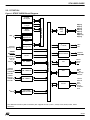
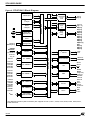
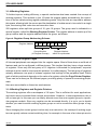
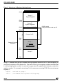
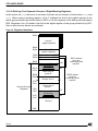
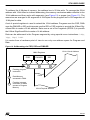
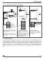
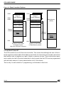
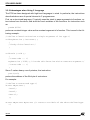
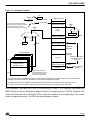
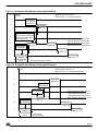
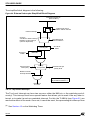
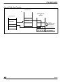
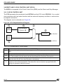
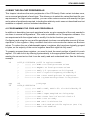
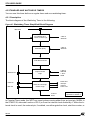
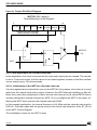
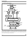
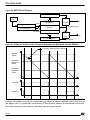
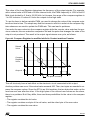
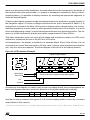
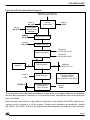
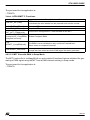
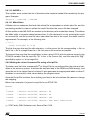
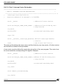
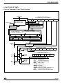
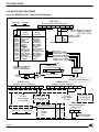
ST9 USER GUIDE
3.4.1 Interrupt Vectors
Unlike most microcontrollers, the ST9 uses a two-level indirect interrupt vector system. This
means that each peripheral able to generate interrupt requests has a vector register that
points to a location in program memory (the vector array). This location contains the address
of the start of the interrupt service routine. This allows each peripheral to generate several different interrupt requests: the peripheral vector register points to an array of pointers to routines, each routine responding to a different interrupt cause. All pointers to interrupt processing routines, except the Reset, must be located in the first 256 bytes of the Interrupt Service Routine (ISR) segment (one of the 64 code segments). The trap for divide by zero with
the associated far call to the Interrupt Service Routine has to be repeated in all memory segments containing programs that perform division. Code may also reside in this 256-byte
space, provided that it does not overlap with the interrupt vectors.
Figure 15 shows the complete mechanism of the 22-bit address construction from the interrupt
which provides the Interrupt Vector Register value to the return from interrupt.
For each peripheral, the layout of the vector array is specified in the section related to its own
Interrupt Vector Register.
42/146