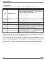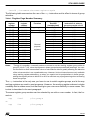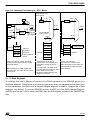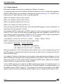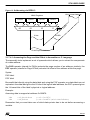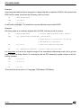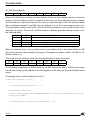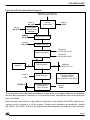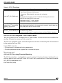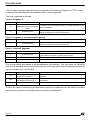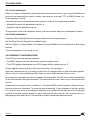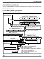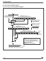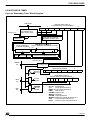
1
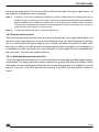
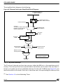
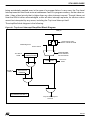
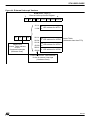
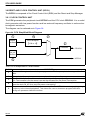
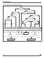
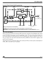
ST9 USER GUIDE
4.6.1.2.3 Interrupt Vectors
The interrupt vector scheme has been explained in Section 3.4.1 using the example of the
MFT to illustrate the mechanism. Here is the equivalent table for the SCI giving the position of
the four vectors dedicated to the four interrupt causes.
Value in IVR
50
Address in ROM of the Value of the Pointer to interrupt
selected pointer
routine
Receiver error
50
Address of error processing routine
Address of Address match processBreak detect or address match
50+2
ing routine
Receiver data ready or DMA end of
Address of receive DMA end of block
50+4
block
processing routine
Transmitter buffer empty of DMA end
Address of transmit DMA end of block
50+6
of block
processing routine
Interrupt cause
4.6.2 SCI Application 1: Sending Bytes using Interrupts
This application sends 10 bytes to the USART. An interrupt is generated at the end of every
single byte transmission. During this interrupt routine, the TXBR register is loaded with the
next byte to be transmitted. This application is found in the SCI/appli directory.
The character format is: 2400 bauds, 8 data bits, 1 stop bit and odd parity. Sent bytes can be
received on a PC loaded with a serial communication management software program such as
Hyperteminal.
4.6.3 SCI Application 2: Sending Bytes using DMA
This application sends bytes from the memory to the SCI peripheral using a DMA channel.
The transfer is re-initialized twice in the DMA End of Block interrupt routine so that data is
transmitted three times. This application is found in the SCI/appli2 directory.
4.6.4 SCI Application 3: Sending and Receiving Bytes using DMA
This application sends bytes from the memory to SCI and receives bytes from SCI to the register file using two DMA channels. The SCI cell is configured in loopback so that each byte
sent is immediately received by the SCI. This application is found in the SCI/appli3 directory.
4.6.5 SCI Application 4: Matching Input Bytes
This application receives bytes from the USART and reacts only if an “F” (upper case) is received: on a character match, a “0” is displayed on the 7-segment LED display on port 4. This
application is found in the SCI/appli4 directory.
97/146