1
Ordering Information
Using the Master Development System
Ordering Information
Part Number
Description
MDEV-***-HH-LR8-MS
MS Long-Range Transmitter Master Development System
*** = 315, 418 (Standard) or 433.92MHz
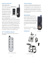
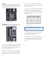
1. Press and hold the CREATE button on the transmitter to create a new
Code Word. This is done by sticking a paper clip through the hole on
the back of the case and pressing the button inside. The Code Word is
randomized for as long as the button is held down. Once comfortable
that the number is sufficiently random, release the button.
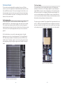
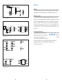
Figure 2: Ordering Information
MS Series Decoder Development Board
5
8
9
1
6
7
11
2
3. Press the LEARN button on the decoder board and the MODE_IND
LED starts flashing. Press any of the data line buttons on the transmitter and press the LEARN button again. The encoder’s Code Word has
now been learned by the decoder and they will operate together.
Troubleshooting
12
If the boards fail to work out of the box, then try the following:
14
3
2. Once the button is released, the MODE_IND LED begins flashing to
indicate that it is ready to accept Control Permissions. Press all of the
data line buttons that are to be recognized, then press the CREATE
button again or let it time out after seventeen seconds.
10
13
4
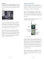
Using the Master Development System is straightforward. After unpacking the board, screw the antenna onto the connector, install the supplied
9V battery, and turn on the power switch. The encoder and decoder are
configured from the factory and work straight out of the box. To create a
new address (if desired), follow these easy steps:
•
Check the battery to make sure it is not dead.
•
Make sure the baud rate switches are set to 9,600bps on the decoder
board.
•
Make sure that the antenna is connected.
•
Check to see if the PDN switch is on, placing the decoder into Power
Down Mode. In most cases, the decoder PDN switch should be on.
•
Make sure that the Control Permissions are set correctly. If the encoder
has not been set to use a particular line, then when that button is
pressed on the transmitter, the MODE_IND LED on the decoder board
lights up, but the data line LED does not light up.
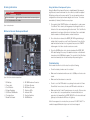
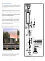
Figure 3: The MS Series Decoder Development Board
1. 9V Battery
2. Power Jack
3. On-Off Switch
4. Voltage Regulator
5. QS Series USB Module
6. Prototype Area
7. Break-Out Header
8. RP-SMA Antenna Connector
9. LR Series Receiver
10. MS Series Decoder
11. Data Line LEDs
12. Indicator LEDs
13. Function Switches
14. LEARN Button
If all of these appear to be in order, then you can call +1 800 736 6677 or
e-mail [email protected] for technical support.
– 2 –
– 3 –