1
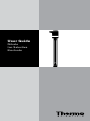
User Guide
Nitrate
Ion Selective
Electrode
ROSS and the COIL trade dress are trademarks of Thermo Fisher Scientific Inc.
AQUAfast, Cahn, ionplus, KNIpHE, No Cal, ORION, perpHect, PerpHecT, PerpHecTion,
pHISA, pHuture, Pure Water, Sage, Sensing the Future, SensorLink, ROSS, ROSS
Ultra, Sure-Flow, Titrator PLUS and TURBO2 are registered trademarks of
Thermo Fisher.
1-888-pHAX-ION, A+, All in One, Aplus, AQUAsnap, AssuredAccuracy, AUTO-BAR,
AUTO-CAL, AUTO DISPENSER, Auto-ID, AUTO-LOG, AUTO-READ, AUTO-STIR, Auto-Test,
BOD AutoEZ, Cable-Free, CERTI-CAL, CISA, DataCOLLECT, DataPLUS, digital LogR,
DirectCal, DuraProbe, Environmental Product Authority, Extra Easy/Extra Value,
FAST QC, GAP, GLPcal, GLPcheck, GLPdoc, ISEasy, KAP, LabConnect, LogR, Low
Maintenance Triode, Minimum Stir Requirement, MSR, NISS, One-Touch, One-Touch
Calibration, One-Touch Measurement, Optimum Results, Orion Star, Pentrode,
pHuture MMS, pHuture Pentrode, pHuture Quatrode, pHuture Triode, Quatrode,
QuiKcheK, rf link, ROSS Resolution, SAOB, SMART AVERAGING, Smart CheK, SMART
STABILITY, Stacked, Star Navigator 21, Stat Face, The Enhanced Lab, ThermaSense,
Triode, TRIUMpH, Unbreakable pH, Universal Access are trademarks of
Thermo Fisher.
Guaranteed Success and The Technical Edge are service marks of Thermo Fisher.
PerpHecT meters are protected by U.S. patent 6,168,707.
PerpHecT ROSS are protected by U.S. patent 6,168,707.
ORION Series A meters and 900A printer are protected by U.S. patents 5,198,093,
D334,208 and D346,753.
ionplus electrodes and Optimum Results solutions are protected by
US Patent 5,830,338.
ROSS Ultra electrodes are protected by US patents 6,793,787.
Orion ORP Standard is protected by US Patent 6,350,367.
Orion NoCal electrodes are protected by US Patent 7,276,142.
© 2008 Thermo Fisher Scientific Inc. All rights reserved. All trademarks are the
property of Thermo Fisher Scientific Inc. and its subsidiaries.
The specifications, descriptions, drawings, ordering information and part numbers
within this document are subject to change without notice.
This publication supersedes all previous publications on this subject.
Table of Contents
Introduction . . . . . . . . . . . . . . . . . . . . . . . . . . . . . . . . . . . . . . 1
Required Equipment . . . . . . . . . . . . . . . . . . . . . . . . . . . . . . . 2
Serial Dilutions . . . . . . . . . . . . . . . . . . . . . . . . . . . . . . . . . . . 4
Electrode Setup . . . . . . . . . . . . . . . . . . . . . . . . . . . . . . . . . . 5
9307BNWP Nitrate Half-Cell Electrode Preparation . . . . . . . . . . 5
900200 Double Junction Reference Electrode Preparation . . . . . 5
9707BNWP Nitrate Combination Electrode Preparation . . . . . . 6
Checking Electrode Operation (Slope) . . . . . . . . . . . . . . . . . . . . . 8
Measurement Units . . . . . . . . . . . . . . . . . . . . . . . . . . . . . . . . . . . 9
Sample Requirements . . . . . . . . . . . . . . . . . . . . . . . . . . . . . . . . . 9
Measuring Hints . . . . . . . . . . . . . . . . . . . . . . . . . . . . . . . . . . . . 10
Electrode Storage . . . . . . . . . . . . . . . . . . . . . . . . . . . . . . . . . . . 11
Electrode Maintenance . . . . . . . . . . . . . . . . . . . . . . . . . . . . . . . 12
Analytical Techniques . . . . . . . . . . . . . . . . . . . . . . . . . . . . 14
Direct Calibration Technique . . . . . . . . . . . . . . . . . . . . . . . . . . . .
Small Volume Direct Calibration Technique . . . . . . . . . . . . . . . .
Low Level Calibration Technique . . . . . . . . . . . . . . . . . . . . . . . .
Known Addition Technique . . . . . . . . . . . . . . . . . . . . . . . . . . . . .
16
20
24
26
Electrode Characteristics . . . . . . . . . . . . . . . . . . . . . . . . . 34
Electrode Response . . . . . . . . . . . . . . . . . . . . . . . . . . . . . . . . . 34
Reproducibility . . . . . . . . . . . . . . . . . . . . . . . . . . . . . . . . . . . . . . 34
Limits of Detection . . . . . . . . . . . . . . . . . . . . . . . . . . . . . . . . . . 35
Electrode Life . . . . . . . . . . . . . . . . . . . . . . . . . . . . . . . . . . . . . . .35
Temperature Effects . . . . . . . . . . . . . . . . . . . . . . . . . . . . . . . . . 36
Interferences . . . . . . . . . . . . . . . . . . . . . . . . . . . . . . . . . . . . . . . 37
Theory of Operation . . . . . . . . . . . . . . . . . . . . . . . . . . . . . . . . . 40
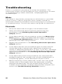
Troubleshooting . . . . . . . . . . . . . . . . . . . . . . . . . . . . . . . . . 42
Assistance . . . . . . . . . . . . . . . . . . . . . . . . . . . . . . . . . . . . . . . . . 43
Warranty . . . . . . . . . . . . . . . . . . . . . . . . . . . . . . . . . . . . . . . . . . 43
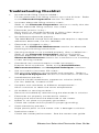
Troubleshooting Checklist . . . . . . . . . . . . . . . . . . . . . . . . . . . . . 44
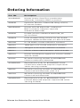
Ordering Information . . . . . . . . . . . . . . . . . . . . . . . . . . . . . 45
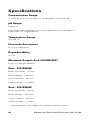
Specifications . . . . . . . . . . . . . . . . . . . . . . . . . . . . . . . . . . . 46
Nitrate Ion Selective Electrode User Guide
II
Nitrate Ion Selective Electrode User Guide
Introduction
This user guide contains information on the preparation,
operation and maintenance for the nitrate ion selective electrode
(ISE). General analytical procedures, electrode characteristics
and electrode theory are also included in this user guide. Nitrate
electrodes measure free nitrate ions in aqueous solutions quickly,
simply, accurately and economically.
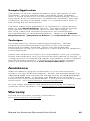
Technical Support Chemists can be consulted for assistance
and troubleshooting advice. Within the United States call
1.800.225.1480 and outside the United States call 978.232.6000
or fax 978.232.6031. In Europe, the Middle East and Africa,
contact your local authorized dealer. For the most current
contact information, visit www.thermo.com/contactwater.
For the latest application and technical resources for Thermo
Scientific Orion products, visit www.thermo.com/waterapps.
Nitrate ionplus® Sure-Flow® Plastic Membrane
Combination ISE, Cat. No. 9707BNWP
The nitrate combination electrode has the sensing and reference
half-cells built into one electrode, which decreases the amount
of required solutions and reduces waste. The built-in Sure-Flow
reference junction prevents electrode clogging and provides
fast and stabile readings. The nitrate combination electrode is
available with a waterproof BNC connector, Cat. No. 9707BNWP.
Electrodes with a waterproof BNC connector can be used on any
ISE or mV meter with a BNC connection.
Nitrate Plastic Membrane Half-Cell ISE,
Cat. No. 9307BNWP
The nitrate half-cell electrode must be used with the
double junction reference electrode, Cat. No. 900200. The
nitrate half-cell electrode is available with a waterproof BNC
connector, Cat. No. 9307BNWP. Electrodes with a waterproof
BNC connector can be used on any ISE or mV meter with a
BNC connection.
Nitrate Ion Selective Electrode User Guide
Required Equipment
1.
Thermo Scientific Orion ISE meter, such as the 4-Star pH/ISE
meter or 5-Star pH/ISE/DO/conductivity meter; equivalent
ISE meter; or mV meter with a 0.1 mV resolution.
Nitrate electrodes can be used on any ISE or mV meter
with a BNC connection. The electrodes can also be used
on meters with a variety of inputs when an adapter cable is
used. Visit www.thermo.com/water for details.
2. Thermo Scientific Orion nitrate electrode.
The 9307BNWP nitrate half-cell electrode requires a
separate reference electrode, Cat. No. 900200.
3. Magnetic stirrer or Thermo Scientific Orion stirrer probe,
Cat. No. 096019. The stirrer probe can be used with 3-Star,
4-Star and 5-Star benchtop meters.
4. Volumetric flasks, graduated cylinders and beakers. Plastic
labware is required for low level nitrate analysis.
5. Distilled or deionized water.
6. Nitrate electrode filling solution.
Use Optimum Results™ F filling solution, Cat. No. 900046,
for the 9707BNWP nitrate combination electrode.
Use inner chamber filling solution, Cat. No. 900002, and
nitrate ISA, Cat. No. 930711, or Optimum Results F filling
solution, Cat. No. 900046, for the double junction reference
electrode that is used with the 9307BNWP nitrate half-cell
electrode. Either the nitrate ISA or Optimum Results F filling
solution can be used as the outer chamber filling solution.
7.
Nitrate calibration standards.
Cat. No.
Description
920706
0.1 M NaNO3 nitrate calibration standard
920707
1000 ppm as N nitrate calibration standard
930707
100 ppm as N nitrate calibration standard
Nitrate Ion Selective Electrode User Guide
8. Nitrate ionic strength adjuster (ISA), Cat. No. 930711.
ISA provides a constant background ionic strength for
samples and standards.
Nitrate interference suppressor solution (NISS), Cat. No.
930710, can be used in place of the nitrate ISA to remove a
variety of interfering anions, including chloride ions, present
in samples such as drinking water, wastewater and soils.
Refer to the Interferences section for details.
9. Preservative solution – add 1 mL of preservative solution to
every 100 mL of standards and samples to prevent biological
degradation of the solutions.
Prepare a 1 M boric acid preservative solution by dissolving
6.2 grams of reagent-grade boric acid in 100 mL of boiling
water. Let the solution cool.
Nitrate Ion Selective Electrode User Guide
Serial Dilutions
Serial dilution is the best method for the preparation of
standards. Serial dilution means that an initial standard is diluted,
using volumetric glassware, to prepare a second standard
solution. The second standard is similarly diluted to prepare a
third standard, and so on, until the desired range of standards
has been prepared.
1. To prepare a 10-2 M standard (140 ppm as N) –
Pipet 10 mL of the 0.1 M standard into a 100 mL volumetric
flask. Dilute to the mark with deionized water and mix well.
2. To prepare a 10-3 M standard (14.0 ppm as N) –
Pipet 10 mL of the 10-2 M standard into a 100 mL volumetric
flask. Dilute to the mark with deionized water and mix well.
3. To prepare a 10-4 M standard (1.40 ppm as N) –
Pipet 10 mL of the 10-3 M standard into a 100 mL volumetric
flask. Dilute to the mark with deionized water and mix well.
To prepare standards with a different concentration use the
following formula:
C1 * V1 = C2 * V2
C1 = concentration of original standard
V1 = volume of original standard
C2 = concentration of standard after dilution
V2 = volume of standard after dilution
For example, to prepare 100 mL of a 100 ppm nitrate standard
from a 1400 ppm nitrate standard:
C1 = 1400 ppm nitrate
V1 = unknown
C2 = 100 ppm nitrate
V2 = 100 mL
1400 ppm * V1 = 100 ppm * 100 mL
V1 = (100 ppm * 100 mL) / 1400 ppm = 7.14 mL
Nitrate Ion Selective Electrode User Guide
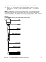
Electrode Setup
9307BNWP Nitrate Half-Cell
Electrode Preparation
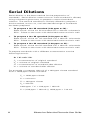
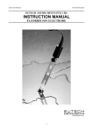
Remove the sensing module from the vial and save the vial for
electrode storage. Make sure that the rubber electrode washer
on the sensing module is in place. See Figure 1. Screw the
sensing module into the electrode body until the module is
finger-tight. To ensure electrical continuity, shake the electrode
down like a clinical thermometer. Rinse the nitrate electrode
with distilled water and then soak it in a 100 ppm or 10-2 M
nitrate standard for 1 to 2 hours prior to use.
Note: Do not immerse the electrode past the rubber
electrode washer.
900200 Double Junction Reference
Electrode Preparation
Prepare the reference electrode according to the reference
electrode user guide. Fill the reference electrode with inner
chamber filling solution, Cat. No. 900002, and either nitrate ISA,
Cat. No. 930711, or Optimum Results F filling solution, Cat. No.
900046 as the outer chamber filling solution.
Note: Do not use the outer chamber filling solution that ships
with the 900200 double junction reference electrode because it
contains interferences for nitrate measurements.
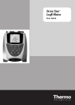
Figure 1
9307BNWP Nitrate Half-Cell Electrode
Electrode Body
Washer
Sensing Module
Sensing Membrane
Nitrate Ion Selective Electrode User Guide
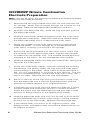
9707BNWP Nitrate Combination
Electrode Preparation
Note: Do not to touch the sensing membrane or reference pellet
during the electrode assembly.
1.
Remove the sensing module from the vial and save the vial
for storage. Make sure that both O-rings are in place on the
module. Remove the electrode handle from the box.
2. Unscrew the electrode cap. Slide the cap and spring down
the electrode cable.
3. Hold the outer body sleeve and gently push the inner stem
through the outer body. Slide the outer body sleeve down
the electrode cable until it is beyond the inner stem.
4. Grasp the middle of the inner stem without touching the
reference pellet. If a red storage tip is connected to the
inner stem, unscrew it and save it for storage.
5. Screw the sensing module into the stem until it stops and
the module is flush against the stem. Tighten the module
an additional one-quarter turn. The module should be firmly
attached to the stem. Do not overtighten the module.
6. Hold the electrode cable and slide the outer body, spring and
cap over the inner stem.
7.
Grasp the outer body sleeve, without touching the sensing
membrane, and gently screw the cap onto the inner stem
while pulling on the cable. Stop when an opposite force is
felt. Do not overtighten or continue to turn the cap. The cap
will not completely stop. If the inner body turns at all, the
cap is too tight. Remove the cap and reassemble.
8. Press on the top of the cap with your thumb to make sure
that the electrode has a smooth flushing motion and the
outer body sleeve returns to its original position.
9. Install the flip spout cap onto the Optimum Results F filling
solution bottle and lift the flip spout to a vertical position.
Insert the spout into the electrode fill hole and add a small
amount of filling solution to the reference chamber.
10. Hold the electrode body and use your thumb to push down
on the electrode cap to allow a few drops of filling solution
to drain out of the electrode. Release the electrode cap.
11. If the sleeve does not return to its original position, add
filling solution and repeat step 10 until the sleeve returns to
its original position.
Nitrate Ion Selective Electrode User Guide
12. Add filling solution to the electrode up to the fill hole.
13. Rinse the electrode with distilled water and soak it in a
100 ppm or 10-2 M nitrate standard for 1 to 2 hours prior
to use.
Note: Add filling solution each day before using the electrode.
The filling solution level should be at least one inch above the
level of sample in the beaker to ensure a proper flow rate. The fill
hole should always be open when taking measurements.
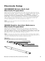
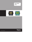
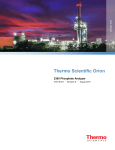
Figure 2
9707BNWP Nitrate Combination Electrode
cap
spring
fill hole
outer body sleeve
inner stem
reference pellet
O-rings
sensing module
sensing membrane
Nitrate Ion Selective Electrode User Guide
Checking Electrode Operation (Slope)
These are general instructions that can be used with most
meters to check the electrode operation. Refer to the meter user
guide for more specific information.
This procedure measures electrode slope. Slope is defined
as the change in millivolts observed with every tenfold change
in concentration. Obtaining the slope value provides the best
means for checking electrode operation.
1.
If the electrode has been stored dry, prepare the electrode
as described in the Electrode Preparation section.
2. Connect the electrode to a meter with a mV mode. Set the
meter to the mV mode.
3. Add 100 mL of distilled water and 2 mL of ISA, Cat. No.
930711, into a 150 mL beaker. Stir the solution thoroughly.
4. Rinse the electrode with distilled water and place the
electrode into the solution prepared in step 3.
5. Select either a 0.1 M or 1000 ppm nitrate standard. Pipet
1 mL of the standard into the beaker and stir the solution
thoroughly. When a stable reading is displayed, record the
electrode potential in millivolts.
6. Pipet 10 mL of the same standard into the same beaker
and stir the solution thoroughly. When a stable reading is
displayed, record the electrode potential in millivolts.
7. There should be a -54 to -60 mV difference between the two
millivolt readings when the solution temperature is between
20 to 25 °C. If the millivolt potential is not within this range,
refer to the Troubleshooting section.
Nitrate Ion Selective Electrode User Guide
Measurement Units
Nitrate concentration can be measured in moles per liter (M),
parts per million (ppm) or any convenient concentration unit.
Table 1
Concentration Unit Conversion Factors
Moles/Liter (M)
ppm as NO3-
ppm as N
1.0
62000
14000
10-1
6200
1400
10-2
620
140
10-3
62.0
14.0
10-4
6.20
1.40
Sample Requirements
All samples must be aqueous and must not contain organic
solvents. Contact Technical Support for information on using the
electrode for specific applications.
The solution temperature must be less than 40 °C.
Samples and standards should be at the same temperature. A
1 °C difference in temperature for a 10-3 M nitrate solution will
give rise to about a 1.5% error.
Interferences should be absent from all samples. See the
Interferences section for a list of possible interferences. If
interferences are present in the sample and cannot be removed,
use the nitrate interference suppressor solution (NISS), Cat. No.
930710, in a 1:1 ratio of solution to NISS. Do not use ISA when
using the nitrate interference suppressor solution.
In all analytical procedures, ISA or NISS must be added to all
samples and standards before measurements are taken.
Nitrate Ion Selective Electrode User Guide
Measuring Hints
•
Stir all standards and samples at a uniform, moderate rate.
Place a piece of insulating material, such as Styrofoam or
cardboard, between the magnetic stir plate and beaker to
prevent measurement errors from the transfer of heat to
the sample.
•
Always use freshly prepared standards for calibration.
•
Always rinse the electrode with distilled water between
measurements and shake the electrode to remove the
water and prevent sample carryover. Do not wipe or rub the
electrode sensing module.
•
Store the nitrate electrode in a 10-2 M or 100 ppm nitrate
standard between measurements.
•
The 9307BNWP nitrate half-cell electrode should be
immersed in standards and samples to approximately
half the length of the nitrate module. Do not immerse
the nitrate electrode past the electrode washer. Immerse
the reference electrode to the same depth as the nitrate
electrode.
•
Allow all standards and samples to reach the same
temperature for precise measurements.
•
Verify the electrode calibration every two hours by placing
the electrode in a fresh aliquot of the least concentrated
standard used for calibration. If the value has changed by
more than 2%, recalibrate the electrode.
•
After immersing the electrode in a solution, check the
electrode sensing surface for air bubbles and remove air
bubbles by reimmersing the electrode in the solution and
gently tapping it.
•
For high ionic strength samples, prepare standards with a
background composition similar to the sample.
•
The fill hole cover must be open during measurements to
ensure a uniform flow of filling solution.
•
If the combination electrode is used and the electrode is
used in dirty or viscous samples or the electrode response
becomes sluggish, empty the electrode completely, hold
the junction open and flush the junction with distilled water.
Empty any water from the electrode and refill it with fresh
filling solution. Press down on the electrode cap to let a few
drops of the filling solution flow out of the electrode and
then replenish any lost solution.
10
Nitrate Ion Selective Electrode User Guide
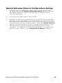
Electrode Storage
Nitrate Combination Electrode Storage,
Cat. No. 9707BNWP
For storage between measurements and up to three days, store
the electrode in a 10-2 M or 100 ppm nitrate standard. The filling
solution inside the electrode should not be allowed to evaporate,
as crystallization will result.
For storage longer than one week, drain the electrode, flush
the reference chamber with distilled water, disassemble the
electrode and store the sensing module in the glass vial.
1.
Grasp the outer body sleeve and unscrew the electrode cap.
Slide the cap and spring assembly down the electrode cable.
2. Push the inner stem of the electrode handle out through the
outer electrode sleeve, exposing the sensing module.
3. Rinse the inner stem and module well with distilled water.
Gently blot dry to prevent damaging the sensing module.
4. Carefully unscrew the sensing module from the inner stem,
taking care not to touch the sensing membrane.
5. Place the nitrate sensing module in the glass vial until it is
needed again. Gently blot dry the inside of the inner stem
and O-ring area, reassemble the electrode handle without
the module and store it dry.
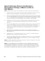
Nitrate Half-Cell Electrode Storage,
Cat. No. 9307BNWP
The nitrate half-cell electrode should be rinsed thoroughly with
distilled water and stored a 10-2 M or 100 ppm nitrate standard.
When storing the electrode for more than three days, rinse the
nitrate half-cell electrode thoroughly with distilled water, shake
the electrode dry, disassemble the electrode and store the
sensing module in the glass vial.
Double Junction Reference Electrode Storage,
Cat. No. 900200
The double junction reference electrode may be stored in
the nitrate ISA or Optimum Results F filling solution between
sample measurements and up to one week. The filling solution
inside the electrode should not be allowed to evaporate, as
crystallization will result.
For storage longer than one week, drain the reference electrode,
flush the inside with distilled water and store the electrode dry.
Nitrate Ion Selective Electrode User Guide
11
Electrode Maintenance
Cleaning the Nitrate Sensing Module
If the electrode is exposed to high levels of interfering ions, it
may drift and become sluggish in response. When this happens,
restore normal performance by soaking the electrode for an
hour in distilled water, emptying the old filling solution, filling
the electrode with fresh filling solution and then soaking the
electrode for a few hours a 10-2 M or 100 ppm nitrate standard.
If soaking the electrode does not restore normal electrode
performance, replace the nitrate sensing module.
Nitrate Combination Electrode and Double Junction
Reference Electrode Flushing
If the area between the electrode outer body and inner cone
becomes clogged with sample or precipitate, flush the area with
filling solution or distilled water.
1.
Hold the electrode body with one hand and use your thumb
to push down on the electrode cap to drain all of the filling
solution out of the electrode.
2. Fill the electrode with distilled water and then push down
on the cap until all the water is drained from the chamber.
Repeat this procedure until all of the sample or precipitate is
removed from the electrode.
3. Fill the electrode with fresh filling solution up to the fill hole.
Push down on the cap to allow a few drops of filling solution
to drain out of the electrode and then replenish the lost
filling solution.
4. Rinse the electrode with distilled water and soak it in a
10-2 M or 100 ppm nitrate standard for 1 to 2 hours.
12
Nitrate Ion Selective Electrode User Guide
Replacing the Nitrate Sensing Module
The sensing membrane of plastic membrane electrodes will
wear over time, indicated by low slope values, drift, poor
reproducibility and loss of response in low level samples. The
electrode response can be restored by replacing the sensing
module. Each sensing module will last about three months with
normal laboratory use, but the actual lifespan of the sensing
module will depend on the type of samples that are measured.
For the 9707BNWP nitrate combination electrode, use the 97
series nitrate module, Cat. No. 970701.
Drain the electrode and flush the reference chamber with
distilled water. Hold the outer body sleeve and unscrew the
electrode cap. Slide the cap and spring assembly down the
electrode cable. Push the inner stem of the electrode handle
out through the outer electrode sleeve, exposing the sensing
module. Rinse the inner stem and module well with distilled
water. Gently blot dry to prevent damaging the sensing module.
Carefully unscrew the sensing module from the inner stem and
dispose of the old sensing module. Obtain a new 97 series
nitrate module, Cat. No. 970701, and refer to the 9707BNWP
Nitrate Combination Electrode Preparation section for
detailed instructions on assembling the electrode.
For the 9307BNWP nitrate half-cell electrode, use the
93 series nitrate module, Cat. No. 930702.
Rinse the electrode with distilled water. Carefully unscrew
the sensing module from the electrode and dispose of the old
sensing module. Obtain a new 93 series nitrate module, Cat.
No. 930702, and refer to the 9307BNWP Nitrate Half-Cell
Electrode Preparation section for detailed instructions on
assembling the electrode.
Nitrate Ion Selective Electrode User Guide
13
Analytical Techniques
A variety of analytical techniques are available to the analyst. The
following is a description of these techniques.
Direct Calibration is a simple procedure for measuring a large
number of samples. Only one meter reading is required for each
sample. Calibration is performed using a series of standards.
The concentration of the samples is determined by comparison
to the standards. ISA is added to all solutions to ensure that
samples and standards have similar ionic strength.
Low Level Calibration is a similar to the direct calibration
technique. This method is recommended when the expected
sample concentration is less than 10-4 M or 1.4 ppm nitrate as
nitrogen (N). A minimum three point calibration is recommended
to compensate for the electrode’s non-linear response at these
concentrations. A special calibration standard preparation
procedure is the best means of preparing low level calibration
standards.
Incremental Techniques provide a useful method for measuring
samples, since a calibration is not required. The different
incremental techniques are described below. They can be
used to measure the total concentration of a specific ion in the
presence of a large (50 to 100 times) excess of complexing
agents. As in direct calibration, any convenient concentration
unit can be used.
Known Addition is useful for measuring dilute samples,
checking the results of direct calibration (when no
complexing agents are present), or measuring the total
concentration of an ion in the presence of an excess
complexing agent. The electrode is immersed in the sample
solution and an aliquot of a standard solution containing the
measured species is added to the sample. From the change
in potential before and after the addition, the original sample
concentration is determined.
14
Nitrate Ion Selective Electrode User Guide
Table 2
Recommended Measuring Techniques
Direct
Small
Volume
Direct
Low Level
[N] < 1.4 ppm
[N] > 1.4 ppm
✔
✔
✔
✔
Occasional
Sampling
✔
Small sample
volume
Large number
of samples
✔
✔
✔
✔
Reduce
chemical
usage
✔
Field
measurement
✔
Ionic
strength
greater than
0.1 M
Known
Addition
✔
Nitrate Ion Selective Electrode User Guide
✔
✔
15
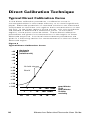
Direct Calibration Technique
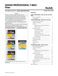
Typical Direct Calibration Curve
In the direct calibration procedure, a calibration curve is
constructed either in the meter memory or on semi-logarithmic
paper. Electrode potentials of standard solutions are measured
and plotted on the linear axis against their concentrations on the
log axis. In the linear regions of the curves, only two standards
are needed to determine a calibration curve. In non-linear
regions, more points must be taken. These direct calibration
procedures are given for concentrations in the region of linear
electrode response. Low level measurement procedures are
given in a following section for measurements in the non-linear
electrode region.
Figure 3
Typical Direct Calibration Curve
- 85
- 65
electrode
potential
(relative mV)
- 45
- 25
-5
+ 15
+ 35
10-fold change
56mV
+ 55
+ 75
+ 95
+ 115
+ 135
.1
.1
1
1
10
10
100 1000
100 1000
10-6 10-5 10-4 10-3 10-2 10-1
16
ppm Nitrate
as N
ppm Nitrate
as NO3
molarity
Nitrate Ion Selective Electrode User Guide
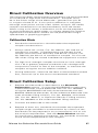
Direct Calibration Overview
The following direct measurement procedures are recommended
for moderate to high level measurements. Samples must
be in the linear range of the electrode – greater than 10-4 M
or 1.4 ppm nitrate as N. A two point calibration is sufficient,
although more points can be used. When using an ISE meter,
sample concentrations can be read directly from the meter.
When using a mV meter, a calibration curve can be prepared
on semi-logarithmic graph paper, or a linear regression (against
logarithmic concentration values) can be performed using a
spreadsheet or graphing program.
Calibration Hints
•
Standard concentrations should bracket the expected
sample concentrations.
•
Always add 2 mL of ISA, Cat. No. 930711, per 100 mL of
standard or sample. If interferences are present in the
sample and cannot be removed, add 50 mL of NISS, Cat.
No. 930710, per 50 mL of standard or sample. Do not use
ISA when using the nitrate interference suppressor solution.
•
For high ionic strength samples that have an ionic strength
of 0.1 M or greater, prepare standards with a background
composition similar to that of the samples, or measure the
samples using the known addition method.
•
During calibration, measure the least concentrated standard
first, and work up to the most concentrated standard.
Direct Calibration Setup
1.
Prepare the electrode as described in the Electrode
Preparation section. If using the 9707BNWP combination
nitrate electrode, fill the electrode with Cat. No. 900046. If
using the 9307BNWP half-cell nitrate electrode with the
900200 reference electrode, fill the reference electrode with
inner chamber filling solution, Cat. No. 900002, and nitrate
ISA, Cat. No. 930711, or Optimum Results F filling solution,
Cat. No. 900046 as the outer chamber filling solution.
2. Connect the electrode to the meter.
3. Prepare at least two standards that bracket the expected
sample range and differ in concentration by a factor of ten.
Standards can be prepared in any concentration unit to suit
the analysis requirement. See the Serial Dilution section
for instructions preparing standards. All standards should be
at the same temperature as the samples.
Nitrate Ion Selective Electrode User Guide
17
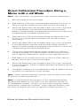
Direct Calibration Procedure Using a
Meter with an ISE Mode
Note: See the meter user guide for more specific information.
1.
Add 100 mL of the less concentrated standard and 2 mL of
ISA to a 150 mL beaker and stir the solution thoroughly.
2. Rinse the electrode with distilled water, blot it dry and place
it into the beaker with the less concentrated standard. Wait
for a stable reading and adjust the meter to display the value
of the standard, as described in the meter user guide.
3. Add 100 mL of the more concentrated standard and 2 mL
of ISA to a second 150 mL beaker and stir the solution
thoroughly.
4. Rinse the electrode with distilled water, blot it dry and place
it into the beaker with the more concentrated standard.
Wait for a stable reading and adjust the meter to display the
value of the second standard, as described in the meter
user guide.
5. Record the resulting slope value. The slope should be
between -54 and -60 mV when the standards are between
20 and 25 °C.
6. Add 100 mL of sample and 2 mL of ISA to a clean 150 mL
beaker and stir the solution thoroughly.
7.
Rinse the electrode with distilled water, blot it dry and place
it into the sample. The concentration of the sample will be
displayed on the meter.
Note: Other solution volumes may be used, as long as the ratio
of solution to ISA remains 50:1.
Note: If interferences are present in the sample and cannot
be removed, add 50 mL of NISS, Cat. No. 930710, per 50 mL
of standard or sample. Do not use ISA when using the nitrate
interference suppressor solution. Other solution volumes may
be used, as long as the ratio of solution to NISS remains 1:1.
18
Nitrate Ion Selective Electrode User Guide
Direct Calibration Procedure Using a
Meter with a mV Mode
Note: See the meter user guide for more specific information.
1. Set the meter to the mV mode.
2. Add 100 mL of the less concentrated standard and 2 mL of
ISA to a 150 mL beaker and stir the solution thoroughly.
3. Rinse the electrode with distilled water, blot it dry and place
it into the beaker with the less concentrated standard.
When a stable reading is displayed, record the mV value and
corresponding standard concentration.
4. Add 100 mL of the more concentrated standard and 2 mL
of ISA to a second 150 mL beaker and stir the solution
thoroughly.
5. Rinse the electrode with distilled water, blot it dry and place
it into the beaker with the more concentrated standard.
When a stable reading is displayed, record the mV value and
corresponding standard concentration.
6. Using semi-logarithmic graph paper, prepare a calibration
curve by plotting the millivolt values on the linear axis and
the standard concentration values on the logarithmic axis.
7. Add 100 mL of sample and 2 mL of ISA to a clean 150 mL
beaker and stir the solution thoroughly.
8. Rinse the electrode with distilled water, blot it dry and place
it into the beaker. When a stable reading is displayed, record
the mV value.
9. Using the calibration curve prepared in step 6, determine the
unknown concentration of the sample.
Note: Other solution volumes may be used, as long as the ratio
of solution to ISA remains 50:1.
Note: If interferences are present in the sample and cannot
be removed, add 50 mL of NISS, Cat. No. 930710, per 50 mL
of standard or sample. Do not use ISA when using the nitrate
interference suppressor solution. Other solution volumes may
be used, as long as the ratio of solution to NISS remains 1:1.
Nitrate Ion Selective Electrode User Guide
19
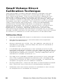
Small Volume Direct
Calibration Technique
Take advantage of special design features available with the
9707BNWP ionplus combination nitrate electrode to meet
your measuring needs. Due to the Sure-Flow reference, this
electrode is able to measure sample volumes as small as 5
mL using a modified direct measurement procedure. Because
less solution volume is required, the chemical usage of nitrate
standards and ISA is reduced. This method is also convenient
when making field measurements, since the 9707BNWP
combination nitrate electrode does not require a separate
reference electrode. All samples should have a concentration
greater than 10-4 M or 1.4 ppm nitrate as N. A two point
calibration is sufficient, although more points can be used.
The following procedure recommends using 25 mL of sample.
Smaller sample volumes can be used, as long as the final volume
of solution is sufficient to cover the bottom of the electrode.
Calibration Hints
•
Use the 9707BNWP ionplus combination nitrate electrode.
•
Standard concentrations should bracket the expected
sample concentrations.
•
Always add 0.5 mL of ISA, Cat. No. 930711, per 25 mL of
standard or sample. Always keep the ratio of standard or
sample to ISA at 50:1.
•
If interferences are present in the sample and cannot be
removed, add 25 mL of NISS, Cat. No. 930710, per 25 mL of
standard or sample. Do not use ISA when using the nitrate
interference suppressor solution. Always keep the ratio of
standard or sample to NISS at 1:1.
•
For high ionic strength samples that have an ionic strength
of 0.1 M or greater, prepare standards with a background
composition similar to that of the samples, or measure the
samples using the known addition method.
•
During calibration, measure the least concentrated standard
first, and work up to the most concentrated standard.
•
Calibrate with the same volume of standard as the volume
of sample that is available for analysis.
20
Nitrate Ion Selective Electrode User Guide
Small Volume Direct Calibration Setup
1.
Prepare the 9707BNWP combination nitrate electrode
as described in the Electrode Preparation section and fill
the electrode with Optimum Results F filling solution,
Cat. No. 900046.
2. Connect the electrode to the meter.
3. Prepare at least two standards that bracket the expected
sample range and differ in concentration by a factor of ten.
Standards can be prepared in any concentration unit to suit
the particular analysis requirement. See the Serial Dilution
section for instructions on how to prepare standards. All
standards should be at the same temperature as the
samples. For details on temperature effects on electrode
performance, refer to the Temperature Effects section.
Nitrate Ion Selective Electrode User Guide
21
Small Volume Direct Calibration
Procedure Using a Meter with an
ISE Mode
Note: See the meter user guide for more specific information.
1.
Add 25 mL of the less concentrated standard and 0.5 mL of
ISA to a 50 mL beaker and swirl the solution to mix.
2. Rinse the electrode with distilled water, blot it dry and place
it into the beaker with the less concentrated standard. Wait
for a stable reading and adjust the meter to display the value
of the standard, as described in the meter user guide.
3. Add 25 mL of the more concentrated standard and 0.5 mL
of ISA to a second 50 mL beaker and swirl the solution
to mix.
4. Rinse the electrode with distilled water, blot it dry and place
it into the beaker with the more concentrated standard.
Wait for a stable reading and adjust the meter to display the
value of the second standard, as described in the meter
user guide.
5. Record the resulting slope value. The slope should be
between -54 and -60 mV when the standards are between
20 and 25 °C.
6. Add 25 mL of sample and 0.5 mL of ISA to a clean 50 mL
beaker and swirl the solution to mix.
7.
Rinse the electrode with distilled water, blot it dry and place
it into the sample. The concentration of the sample will be
displayed on the meter.
Note: Other solution volumes may be used, as long as the ratio
of solution to ISA remains 50:1.
Note: If interferences are present in the sample and cannot
be removed, add 25 mL of NISS, Cat. No. 930710, per 25 mL
of standard or sample. Do not use ISA when using the nitrate
interference suppressor solution. Other solution volumes may
be used, as long as the ratio of solution to NISS remains 1:1.
22
Nitrate Ion Selective Electrode User Guide
Small Volume Direct Calibration
Procedure Using a Meter with a
mV Mode
Note: See the meter user guide for more specific information.
1. Set the meter to the mV mode.
2. Add 25 mL of the less concentrated standard and 0.5 mL of
ISA to a 50 mL beaker and swirl the solution to mix.
3. Rinse the electrode with distilled water, blot it dry and place
it into the beaker with the less concentrated standard.
When a stable reading is displayed, record the mV value and
corresponding standard concentration.
4. Add 25 mL of the more concentrated standard and 0.5 mL
of ISA to a second 50 mL beaker and swirl the solution
to mix.
5. Rinse the electrode with distilled water, blot it dry and place
it into the beaker with the more concentrated standard.
When a stable reading is displayed, record the mV value and
corresponding standard concentration.
6. Using semi-logarithmic graph paper, prepare a calibration
curve by plotting the millivolt values on the linear axis and
the standard concentration values on the logarithmic axis.
7. Add 25 mL of sample and 0.5 mL of ISA to a clean 50 mL
beaker and swirl the solution to mix.
8. Rinse the electrode with distilled water, blot it dry and place
it into the beaker. When a stable reading is displayed, record
the mV value.
9. Using the calibration curve prepared in step 6, determine the
unknown concentration of the sample.
Note: Other solution volumes may be used, as long as the ratio
of solution to ISA remains 50:1.
Note: If interferences are present in the sample and cannot
be removed, add 25 mL of NISS, Cat. No. 930710, per 25 mL
of standard or sample. Do not use ISA when using the nitrate
interference suppressor solution. Other solution volumes may
be used, as long as the ratio of solution to NISS remains 1:1.
Nitrate Ion Selective Electrode User Guide
23
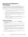
Low Level Calibration
Technique
These procedures are for solutions that have a nitrate
concentration of less than 10-4 M or 1.4 ppm nitrate as N. For
solutions low in nitrate but high in total ionic strength (greater
than 10-1 M), perform the same procedure by preparing a
calibrating solution with a composition similar to the sample.
Accurate results require that the following conditions be met:
•Prepare at least three calibration standards that bracket
the expected sample concentration.
•Always use low level ISA for standards and samples. If
interferences are present in the sample and cannot be
removed, use NISS instead of low level ISA.
•Plastic labware must be used for all low level nitrate
measurements.
•Adequate time must be allowed for electrode
stabilization. Longer response time will be needed at low
level measurements.
• Stir all standards and samples at a uniform rate.
Low Level Setup
1.
Prepare the electrode as described in the Electrode
Preparation section.
2. Connect the electrode to the meter. Set the meter to the
mV mode.
3. Prepare the low level ISA by pipetting 20 mL of the nitrate
ISA, Cat. No. 930711, into a 100 mL volumetric flask and
diluting to the mark with distilled water. Use low level ISA
for low level measurements only.
If interferences are present in the sample and cannot be
removed, use NISS instead of low level ISA. Add 10.1 mL
of NISS, Cat. No. 930710, per 90.9 mL of distilled water
or sample.
4. Select a standard solution. Use either a 100 ppm nitrate as
N or 10-3 M nitrate standard.
24
Nitrate Ion Selective Electrode User Guide
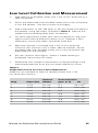
Low Level Calibration and Measurement
1.
Add 100 mL of distilled water and 1 mL of low level ISA to a
150 mL beaker.
2. Rinse the electrode with distilled water, blot it dry and place
it into the beaker. Stir the solution thoroughly.
3. Add increments of the 100 ppm or 10-3 M nitrate standard to
the beaker using the steps outlined in Table 3. Record the
stable millivolt reading after each increment.
4. On semi-logarithmic paper, plot the concentration (log axis)
against the millivolt potential (linear axis). Prepare a new
calibration curve with fresh standards each day.
5. Measure 100 mL of sample and 1 mL of low level ISA
and pour the solutions into a clean 150 mL beaker. Rinse
the electrode with distilled water, blot it dry and place the
electrode into the sample.
6. Stir the solution thoroughly. When a stable reading is
displayed, record the mV value.
7.
Determine the sample concentration corresponding to the
measured potential from the low level calibration curve.
Table 3
Calibration Curve For Low Level Calibrations
Additions of standard to 100 mL distilled water and 1 mL
low level ISA solution.
Step
Pipet Size
Volume
Added
Concentration
ppm as N
M
1
1 mL
0.1 mL
0.1
1.0 x 10⁻⁶
2
1 mL
0.1 mL
0.2
2.0 x 10⁻⁶
3
1 mL
0.2 mL
0.4
3.9 x 10⁻⁶
4
1 mL
0.2 mL
0.6
5.9 x 10⁻⁶
5
1 mL
0.4 mL
1.0
9.8 x 10⁻⁶
6
2 mL
2.0 mL
2.9
2.9 x 10⁻⁵
7
2 mL
2.0 mL
4.7
4.7 x 10⁻⁵
Nitrate Ion Selective Electrode User Guide
25
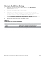
Known Addition Technique
Known addition is a convenient technique for measuring samples
in the linear range of the electrode (greater than 10-4 M or
1.4 ppm nitrate as N) because no calibration curve is required.
It can be used to verify the results of a direct calibration or to
measure the total concentration of an ion in the presence of
a large excess of a complexing agent. The sample potential is
measured before and after addition of a standard solution.
Accurate results require that the following conditions be met:
•Concentration should approximately double as a result of
the addition.
•Sample concentration should be known to within a factor
of three.
•Either no complexing agent or a large excess of the
complexing agent may be present.
•The ratio of the uncomplexed ion to complexed ion must not
be changed by addition of the standard.
•All samples and standards should be at the same
temperature.
•
With double or multiple known addition, the final addition
should be 10 to 100 times the sample concentration.
•
Add 2 mL of ISA to every 100 mL of sample before analysis.
If interferences are present in the sample and cannot be
removed, add 50 mL of NISS, Cat. No. 930710, per 50 mL of
standard or sample. Do not use ISA when using the nitrate
interference suppressor solution.
26
Nitrate Ion Selective Electrode User Guide
Known Addition Setup
1.
Prepare the electrode as described in the Electrode
Preparation section.
2. Connect the electrode to the meter.
3. Prepare a standard solution that will cause the nitrate
concentration of the sample to double when added to the
sample solution. Refer to Table 4 for guidelines.
4. Determine the electrode slope by performing the procedure
in the Checking Electrode Operation (Slope) section.
5. Rinse the electrode with distilled water.
Table 4
Guideline For Known Addition
Volume of Addition
Concentration of Standard
1 mL
100 times sample concentration
5 mL
20 times sample concentration
10 mL*
10 times sample concentration
* Most convenient volume to use
Nitrate Ion Selective Electrode User Guide
27
Known Addition Using a Meter with a
Known Addition Mode
Note: See the meter user guide for more specific information.
1.
Set the meter to measure in the known addition mode.
2. Measure 100 mL of the sample and 2 mL of ISA and pour
the solutions into a beaker. Rinse the electrode with
distilled water and place it into the sample solution. Stir the
solution thoroughly.
3. When a stable reading is displayed, set the meter as
described in the meter user guide, if required.
4. Pipet the appropriate amount of the standard solution into
the beaker. Stir the solution thoroughly.
5. When a stable reading is displayed, record the sample
concentration.
28
Nitrate Ion Selective Electrode User Guide
Known Addition Using a Meter with a
Millivolt Mode
1.
Set the meter to the relative millivolt mode. If a relative
millivolt mode is not available, use the millivolt mode.
2. Measure 100 mL of sample and 2 mL of ISA and pour the
solutions into a 150 mL beaker. Stir the solution thoroughly.
3. Rinse the electrode with distilled water, blot it dry and
place the electrode into the beaker. When a stable reading
is displayed, set the meter to read 0.0 mV. If the reading
cannot be adjusted to 0.0 mV, record the actual mV value.
4. Pipet the appropriate amount of standard solution into the
beaker. Stir the solution thoroughly.
5. When a stable reading is displayed, record the mV value.
If the meter could not be set to 0.0 mV in step 3, subtract
the first reading from the second reading to calculate ∆E.
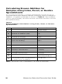
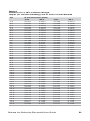
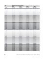
6. Use Table 6 to find the Q value that corresponds to the
change in potential, ∆E. To determine the original sample
concentration, multiply Q by the concentration of the added
standard:
Csample = Q * Cstandard
Cstandard = standard concentration
Csample = sample concentration
Q = value from Table 6
The table of Q values is calculated for a 10% volume change.
The equation for the calculation of Q for different slopes and
volume changes is given below.
Q = (p * r) / {[(1 + p) * 10 ∆E/S] - 1}
Q = value from Table 6
∆E = E2 - E1
S = slope of the electrode
p = volume of standard / volume of sample and ISA
r = volume of sample and ISA / volume of sample
Nitrate Ion Selective Electrode User Guide
29
Calculating Known Addition for
Samples using Lotus, Excel, or Quattro
Spreadsheets
If it is more convenient, a simple spreadsheet can be set up to
calculate the known addition results, using any ratio of sample to
addition. A typical worksheet is shown in Table 5. The numbers
shown are examples, but the formulas and their locations should
be copied exactly.
Table 5
Known Addition Calculations using Lotus, Excel, or Quattro
Spreadsheets
A
B
C
Enter Value
1
2
Volume of sample and ISA (mL)
102
3
Volume of addition (mL)
10
4
Concentration of addition
10
5
Volume of sample
100
6
Initial mV reading
45.3
7
Final mV reading
63.7
8
Electrode slope
-59.2
9
Derived Values
10
11
Delta E
+C7 - C6
12
Solution volume ratio
+C3/C2
13
Antilog term
+10^ (C11/C8)
14
Sample volume ratio
+C2/C5
Q term
+C12*C14/
(((1+C12)*C13)-1)
Calculated initial concentration
in same units as addition
+C15*C4
15
16
Note: For Excel, use = instead of + at start of formulas.
30
Nitrate Ion Selective Electrode User Guide
Table 6
Q Values for a 10% volume change,
slopes (in column heading) are in units of mV/decade
∆E
5.0
5.2
5.4
5.6
5.8
6.0
6.2
6.4
6.6
6.8
7.0
7.2
7.4
7.6
7.8
8.0
8.2
8.4
8.6
8.8
9.0
9.2
9.4
9.6
9.8
10.0
10.2
10.4
10.6
10.8
11.0
11.2
11.4
11.6
11.8
12.0
12.2
12.4
12.6
12.8
13.0
13.2
13.4
13.6
13.8
Q Concentration Ratio
-57.2
-58.2
0.2917
0.2957
0.2827
0.2867
0.2742
0.2781
0.2662
0.2700
0.2585
0.2623
0.2512
0.2550
0.2443
0.2480
0.2377
0.2413
0.2314
0.2349
0.2253
0.2288
0.2196
0.2230
0.2140
0.2174
0.2087
0.2121
0.2037
0.2070
0.1988
0.2020
0.1941
0.1973
0.1896
0.1927
0.1852
0.1884
0.1811
0.1841
0.1770
0.1801
0.1732
0.1762
0.1694
0.1724
0.1658
0.1687
0.1623
0.1652
0.1590
0.1618
0.1557
0.1585
0.1525
0.1553
0.1495
0.1522
0.1465
0.1492
0.1437
0.1463
0.1409
0.1435
0.1382
0.1408
0.1356
0.1382
0.1331
0.1356
0.1306
0.1331
0.1282
0.1307
0.1259
0.1283
0.1236
0.1260
0.1214
0.1238
0.1193
0.1217
0.1172
0.1195
0.1152
0.1175
0.1132
0.1155
0.1113
0.1136
0.1094
0.1117
-59.2
0.2996
0.2906
0.2820
0.2738
0.2660
0.2586
0.2516
0.2449
0.2384
0.2323
0.2264
0.2208
0.2154
0.2102
0.2052
0.2005
0.1959
0.1914
0.1872
0.1831
0.1791
0.1753
0.1716
0.1680
0.1646
0.1613
0.1580
0.1549
0.1519
0.1490
0.1461
0.1434
0.1407
0.1381
0.1356
0.1331
0.1308
0.1284
0.1262
0.1240
0.1219
0.1198
0.1178
0.1158
0.1139
Nitrate Ion Selective Electrode User Guide
-60.1
0.3031
0.2940
0.2854
0.2772
0.2693
0.2619
0.2548
0.2480
0.2416
0.2354
0.2295
0.2238
0.2184
0.2131
0.2081
0.2033
0.1987
0.1942
0.1899
0.1858
0.1818
0.1779
0.1742
0.1706
0.1671
0.1638
0.1605
0.1573
0.1543
0.1513
0.1485
0.1457
0.1430
0.1404
0.1378
0.1353
0.1329
0.1306
0.1283
0.1261
0.1239
0.1218
0.1198
0.1178
0.1159
31
∆E
14.0
14.2
14.4
14.6
14.8
15.0
15.5
16.0
16.5
17.0
17.5
18.0
18.5
19.0
19.5
20.0
20.5
21.0
21.5
22.0
22.5
23.0
23.5
24.0
24.5
25.0
25.5
26.0
26.5
27.0
27.5
28.0
28.5
29.0
29.5
30.0
30.5
31.0
31.5
32.0
32.5
33.0
33.5
34.0
34.5
35.0
35.5
36.0
32
Q Concentration Ratio
-57.2
-58.2
0.1076
0.1098
0.1058
0.1080
0.1041
0.1063
0.1024
0.1045
0.1008
0.1029
0.0992
0.1012
0.0953
0.0973
0.0917
0.0936
0.0882
0.0902
0.0850
0.0869
0.0819
0.0837
0.0790
0.0808
0.0762
0.0779
0.0736
0.0753
0.0711
0.0727
0.0687
0.0703
0.0664
0.0680
0.0642
0.0658
0.0621
0.0637
0.0602
0.0617
0.0583
0.0597
0.0564
0.0579
0.0547
0.0561
0.0530
0.0544
0.0514
0.0528
0.0499
0.0512
0.0484
0.0497
0.0470
0.0483
0.0456
0.0469
0.0443
0.0455
0.0431
0.0443
0.0419
0.0430
0.0407
0.0418
0.0395
0.0407
0.0385
0.0396
0.0374
0.0385
0.0364
0.0375
0.0354
0.0365
0.0345
0.0355
0.0335
0.0345
0.0327
0.0336
0.0318
0.0328
0.0310
0.0319
0.0302
0.0311
0.0294
0.0303
0.0286
0.0295
0.0279
0.0288
0.0272
0.0281
-59.2
0.1120
0.1102
0.1084
0.1067
0.1050
0.1033
0.0994
0.0956
0.0921
0.0887
0.0856
0.0825
0.0797
0.0770
0.0744
0.0719
0.0696
0.0673
0.0652
0.0631
0.0612
0.0593
0.0575
0.0558
0.0541
0.0525
0.0510
0.0495
0.0481
0.0468
0.0455
0.0442
0.0430
0.0418
0.0407
0.0396
0.0385
0.0375
0.0365
0.0356
0.0346
0.0337
0.0329
0.0320
0.0312
0.0305
0.0297
0.0290
-60.1
0.1140
0.1121
0.1103
0.1086
0.1069
0.1052
0.1012
0.0974
0.0938
0.0904
0.0872
0.0841
0.0813
0.0785
0.0759
0.0734
0.0710
0.0687
0.0666
0.0645
0.0625
0.0606
0.0588
0.0570
0.0553
0.0537
0.0522
0.0507
0.0492
0.0479
0.0465
0.0452
0.0440
0.0428
0.0417
0.0406
0.0395
0.0384
0.0374
0.0365
0.0355
0.0346
0.0337
0.0329
0.0321
0.0313
0.0305
0.0298
Nitrate Ion Selective Electrode User Guide
∆E
36.5
37.0
37.5
38.0
38.5
39.0
39.5
40.0
40.5
41.0
41.5
42.0
42.5
43.0
43.5
44.0
44.5
45.0
45.5
46.0
46.5
47.0
47.5
48.0
48.5
49.0
49.5
50.0
50.5
51.0
51.5
52.0
52.5
53.0
53.5
54.0
54.5
55.0
55.5
56.0
56.5
57.0
57.5
58.0
58.5
59.0
59.5
60.0
Q Concentration Ratio
-57.2
-58.2
0.0265
0.0274
0.0258
0.0267
0.0252
0.0260
0.0246
0.0254
0.0240
0.0248
0.0234
0.0242
0.0228
0.0236
0.0223
0.0230
0.0217
0.0225
0.0212
0.0219
0.0207
0.0214
0.0202
0.0209
0.0197
0.0204
0.0192
0.0199
0.0188
0.0195
0.0183
0.0190
0.0179
0.0186
0.0175
0.0181
0.0171
0.0177
0.0167
0.0173
0.0163
0.0169
0.0159
0.0165
0.0156
0.0162
0.0152
0.0158
0.0148
0.0154
0.0145
0.0151
0.0142
0.0147
0.0139
0.0144
0.0135
0.0141
0.0132
0.0138
0.0129
0.0135
0.0126
0.0132
0.0124
0.0129
0.0121
0.0126
0.0118
0.0123
0.0116
0.0120
0.0113
0.0118
0.0110
0.0115
0.0108
0.0113
0.0106
0.0110
0.0103
0.0108
0.0101
0.0106
0.0099
0.0103
0.0097
0.0101
0.0095
0.0099
0.0093
0.0097
0.0091
0.0095
0.0089
0.0093
-59.2
0.0282
0.0275
0.0269
0.0262
0.0256
0.0250
0.0244
0.0238
0.0232
0.0227
0.0221
0.0216
0.0211
0.0206
0.0202
0.0197
0.0192
0.0188
0.0184
0.0179
0.0175
0.0171
0.0168
0.0164
0.0160
0.0157
0.0153
0.0150
0.0146
0.0143
0.0140
0.0137
0.0134
0.0131
0.0128
0.0125
0.0123
0.0120
0.0118
0.0115
0.0113
0.0110
0.0108
0.0105
0.0103
0.0101
0.0099
0.0097
Nitrate Ion Selective Electrode User Guide
-60.1
0.0290
0.0283
0.0276
0.0270
0.0263
0.0257
0.0251
0.0245
0.0239
0.0234
0.0228
0.0223
0.0218
0.0213
0.0208
0.0203
0.0198
0.0194
0.0190
0.0185
0.0181
0.0177
0.0173
0.0169
0.0166
0.0162
0.0158
0.0155
0.0151
0.0148
0.0145
0.0142
0.0139
0.0136
0.0133
0.0130
0.0127
0.0125
0.0122
0.0119
0.0117
0.0114
0.0112
0.0110
0.0107
0.0105
0.0103
0.0101
33
Electrode Characteristics
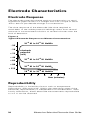
Electrode Response
The electrode potential plotted against concentration on semilogarithmic paper results in a straight line with a slope of about
-54 to -60 mV per decade change in concentration.
The time response of the electrode (the time required to
reach 99% of the stable potential reading) varies from several
seconds in concentrated solutions to several minutes near the
limit of detection.
Figure 4
Typical Electrode Response to Nitrate Concentration
- 35
- 10
+ 15
+ 40
+ 65
+ 90
+ 115
10-3 M to 10-2 M NaNO3
electrode
potential
(mV)
10-3 M to 10-4 M NaNO3
10-3 M to 10-5 M NaNO3
10-3 M to 10-6 M NaNO3
1
2
3
4
5
7
6
time (minutes)
Reproducibility
Reproducibility is limited by factors such as temperature
fluctuations, drift and noise. Within the operating range of the
electrode, reproducibility is independent of concentration. With
hourly calibrations, direct electrode measurements reproducible
to ± 2 % can be obtained.
34
Nitrate Ion Selective Electrode User Guide
Limits of Detection
In pure nitrate solutions, the upper limit of detection is 1 M.
When possible, dilute the sample into the linear range of the
electrode. If samples are not diluted, the possibility of a liquid
reference junction potential and the salt extraction effect, need
to be considered. At high salt concentrations, salts may be
extracted into the electrode membrane, causing deviation from
theoretical response. To measure samples between 10-1 and
1 M, calibrate the electrode at 4 or 5 intermediate points or dilute
the sample.
The lower limit of detection is determined by the slight water
solubility of the ion exchanger, which causes deviation from
theoretical response. Figure 3 shows the theoretical response at
low levels of nitrate compared to the actual response. If nitrate
measurements are made below 10-4 M or 1.4 ppm nitrate as N, a
low level measurement procedure is recommended.
Electrode Life
Each sensing module will last approximately three months
with normal laboratory use, but the actual lifespan of the
sensing module will depend on the type of samples that the
electrode is used in. Refer to the Electrode Maintenance
section for instructions on changing the sensing module. In
time, the electrode slope will decrease and readings will start
to drift, indicating that the module should be changed. Before
replacement, refer to the Troubleshooting section to make sure
that the difficulties are caused by the sensing module.
Nitrate Ion Selective Electrode User Guide
35
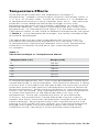
Temperature Effects
Since electrode potentials are affected by changes in
temperature, samples and standard solutions should be within ±
1 °C (± 2 °F) of each other. At the 10-3 M level, a 1 °C difference
in temperature results in errors greater than 1.5 %. The absolute
potential of the reference electrode changes slowly with
temperature because of the solubility equilibria on which the
electrode depends. The slope of the electrode also varies with
temperature, as indicated by the factor S in the Nernst equation.
Theoretical values of the slope at different temperatures are given
in Table 7. If the temperature changes, the meter and electrode
should be recalibrated.
The electrode can be used at temperatures from 0 to 40 °C,
provided that temperature equilibrium has occurred. For use
at temperatures substantially different from room temperature,
calibration standards should be at the same temperature
as samples.
Table 7
Theoretical Slope vs. Temperature Values
Temperature (°C)
Slope (mV)
0
-54.20
10
-56.18
20
-58.16
25
-59.16
30
-60.15
40
-62.13
If sample temperatures vary, use of the 9707BNWP combination
nitrate electrode is recommended. The Optimum Results F filling
solution that is included with the electrode will minimize junction
potentials and provide optimum temperature and time response.
Optimum Results F filling solution produces an isopotential point
of 3.2 x 10⁻³ M nitrate. The isopotential point is the concentration
at which the potential of the electrode does not vary with
temperature. Since the isopotential point of this electrode
is known, the combination nitrate electrode may be used on
meters that allow automatic temperature compensation for ISE
measurements. By programming in the isopotential point and
placing an ATC probe into the sample, any time the temperature
changes the meter will automatically adjust the slope of the
calibration curve, resulting in more accurate measurements.
36
Nitrate Ion Selective Electrode User Guide
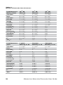
Interferences
Some anions, if present at high enough levels, are electrode
interferences and will cause measurement errors. Table 8
indicates levels of common ions that will cause 10% errors at
different concentrations of nitrate.
The nitrate interference suppressor solution (NISS), Cat.
No. 930710, is recommended for the removal of a variety of
interfering anions present in samples such as soils, drinking
water, wastewater and plant tissues. The nitrate interference
suppressor solution is mixed in an equal volume with samples
and standards. For example, add 50 mL of NISS per 50 mL of
standard or sample. This procedure ensures that samples and
standards have a similar background and that no correction factor
is needed for the dilution. Do not use ISA when using the nitrate
interference suppressor solution.
If the electrode is exposed to high levels of interfering ions, it
may drift and become sluggish in response. When this happens,
restore normal performance by soaking the electrode for an
hour in distilled water, emptying the old filling solution, filling
the electrode with fresh filling solution and then soaking the
electrode for a few hours a 10-2 M or 100 ppm nitrate standard.
If soaking the electrode does not restore normal electrode
performance, refer to the Electrode Maintenance section for
instructions on how to replace the sensing module.
When the level of interferences in samples is constant, it
is sometimes possible to measure nitrate accurately when
interference levels are higher than those in Table 8. For example,
nitrate can be measured in sea water by using synthetic ocean
water for calibration. Contact our Technical Support Chemists for
more information.
Nitrate Ion Selective Electrode User Guide
37
Table 8
Nitrate Electrode Interferences
Interferences
Moles/Liter
10-4 M
Nitrate
10-3 M
Nitrate
10-2 M
Nitrate
(d) ClO4-
1 x 10⁻⁸
1 x 10⁻⁷
1 x 10⁻⁶
10-7
10-6
5 x 10⁻⁵
(b)
5x
I-
5x
(d) ClO3-
5 x 10⁻⁶
5 x 10⁻⁵
5 x 10⁻⁴
(b) CN-
1 x 10⁻⁵
1 x 10⁻⁴
1 x 10⁻³
7x
10-5
7x
10-4
7 x 10⁻³
(c) NO2
7x
10-5
7x
10-4
7 x 10⁻³
(b) HS-
1 x 10⁻⁴
1 x 10⁻³
1 x 10⁻²
(a) HCO3-
1 x 10⁻³
1 x 10⁻²
0.1
10-3
10-2
0.2
(b)
Br-
(a) CO3
2x
(b) Cl-
3 x 10⁻³
3 x 10⁻²
0.3
(b) H2PO4-
5 x 10⁻³
5 x 10⁻²
0.5
(b) HPO4-2
5 x 10⁻³
5 x 10⁻²
0.5
(b) PO4
5x
10-3
5x
10-2
0.5
(e) OAc-
2 x 10⁻²
0.2
2
F-
6 x 10⁻²
0.6
6
SO4-2
0.1
1.0
10
Interferences
ppm
1 ppm
Nitrate as N
10 ppm
Nitrate as N
100 ppm
Nitrate as N
(d) ClO4-
7 x 10⁻⁴
7 x 10⁻³
7 x 10⁻²
(b) I-
4 x 10⁻²
0.4
4
(d) ClO3
0.3
3
30
(b) CN-
0.2
2
20
(b) Br-
4
40
400
(c) NO2-
2
23
230
HS-
2
23
230
(a) HCO3-
44
440
4400
(a) CO3-2
86
860
8600
(b) Cl-
76
760
7600
(b) H2PO4
-
346
3464
34640
(b) HPO4-2
343
3430
34300
(b) PO4-3
339
3390
33900
(e) OAc-
1042
10420
104200
F-
814
8140
81400
SO4-2
6857
68570
685700
-2
-3
-
(b)
38
2x
Nitrate Ion Selective Electrode User Guide
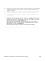
(a) Carbonate and bicarbonate can be removed by acidifying the
sample to pH 4.5 with sulfuric acid, converting the ions to
carbon dioxide.
(b) These interferences can be minimized by precipitation with
silver. Dissolve solid silver sulfate in samples to remove.
(c) Nitrite can be removed by adding sufficient sulfamic acid
to samples.
(d) These interferences cannot be removed. Use the Thermo
Scientific Orion nitrate test kit, Cat. No. 700005, to convert
nitrate to ammonia. Measure samples using the ammonia
electrode, Cat. No. 9512HPBNWP.
As an alternate method, convert nitrate to nitrite with a
reduction column and measure nitrite levels with a nitrite
electrode, Cat. No. 9746BNWP.
For more information contact our Technical Support
Chemists.
(e) Many organic (carboxylic) anions also interfere with the
nitrate electrode. These anions can be removed by using a
1 M ISA solution.
Note: The use of any of the above procedures require similar
treatment of standards as well as samples.
Nitrate Ion Selective Electrode User Guide
39
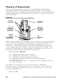
Theory of Operation
The nitrate electrode consists of a replaceable, pretested
sensing module connected to an epoxy body. The sensing
module contains a liquid internal filling solution in contact with a
gelled organophilic membrane that contains a nitrate selective
ion exchanger.
Figure 5
Example of an Ion Sensing Module
module
housing
electrical
contact
internal
reference
element
(Ag/AgCl)
internal
aqueous
reference
solution
porous
plastic
organphilic
membrane
ion
sensitive
area
When the module is in contact with a solution containing nitrate
ions, an electrode potential develops across the module. This
potential, which depends on the level of free nitrate ion in
solution, is measured against a constant reference potential
with a digital pH/mV meter or ISE (concentration) meter. The
measured potential corresponding to the level of nitrate ion in
solution is described by the Nernst equation.
E = Eo + S * log (A)
E = measured electrode potential
Eo = reference potential (a constant)
A = nitrate ion activity level in solution
S = electrode slope (about -57 mV per decade)
S = (2.3 R T) / nF
R and F are constants, T = temperature in degrees K and
n = ionic charge
The level of nitrate ions, A, is the activity or “effective
concentration” of free nitrate ions in solution. The nitrate ion
activity is related to free nitrate ion concentration, Cf, by the
activity coefficient, y.
40
A = y * Cf
Nitrate Ion Selective Electrode User Guide
Ionic activity coefficients are variable and largely depend on total
ionic strength. The ionic strength of a solution is determined
by all of the ions present. It is calculated by multiplying the
concentration of each individual ion by the square of its charge,
adding all these values up and then dividing by two.
Ionic strength = 1/2 ∑ (CiZi2)
Ci = concentration of ion i
Zi = charge of ion i
∑ symbolizes the sum of all the types of ions in solutions
If background ionic strength is high and constant relative to the
sensed ion concentration, the activity coefficient is constant and
activity is directly proportional to concentration. Ionic strength
adjustor (ISA) is added to all nitrate standards and samples so
that the background ionic strength is high and constant relative to
variable concentrations of nitrate. For nitrate, the recommended
ISA is (NH4)2SO4. Nitrate interference suppression solution
(NISS), a specific solution for removal of nitrate-interfering ions, is
recommended for samples with competing ions. Other solutions
can be used as long as they do not contain ions that would
interfere with the electrode response to nitrate.
If samples have a high ionic strength (above 0.1 M), standards
should be prepared with a composition similar to the samples.
Reference electrode conditions must also be considered. Liquid
junction potentials arise any time when two solutions of different
composition are brought into contact. The potential results from
the interdiffusion of ions in the two solutions. Since ions diffuse
at different rates, the electrode charge will be carried unequally
across the solution boundary resulting in a potential difference
between the two solutions. In making electrode measurements,
it is important that this potential is the same when the reference
is in the standardizing solution as well as in the same solution;
otherwise, the change in liquid junction potential will appear as an
error in the measured specific ion electrode potential.
The most important variable that analysts have under their control
is the composition of the liquid junction filling solution. The filling
solution should be equitransferent. That is, the speed with which
the positive and negative ions in the filling solution diffuse into
the sample should be nearly as equal as possible. If the rate at
which positive and negative charge is carried into the sample
solution is equal, then no junction potential can result. Optimum
Results filling solutions are specifically designed to meet all
reference electrode conditions.
Nitrate Ion Selective Electrode User Guide
41
Troubleshooting
Follow a systematic procedure to isolate the problem. The
measuring system can be divided into four components for ease
in troubleshooting: meter, electrode, sample/application
and technique.
Meter
The meter is the easiest component to eliminate as a possible
cause of error. Thermo Scientific Orion meters include an
instrument checkout procedure and shorting cap for convenience
in troubleshooting. Consult the meter user guide for directions.
Electrode
1. Rinse the electrode thoroughly with distilled water.
2. Verify the electrode performance by performing the
procedure in the Checking Electrode Operation
(Slope) section.
3. If the electrode fails this procedure, review the Measuring
Hints section. Clean the electrode thoroughly as directed
in the Electrode Maintenance section. Drain and refill the
electrode with fresh filling solution.
4. Repeat the procedure in the Checking Electrode Operation
(Slope) section.
5. It the electrode fails this procedure again and the half-cell
nitrate electrode is being used, determine whether the
nitrate or reference electrode is at fault. To do this, substitute
a known working electrode for the electrode in question and
repeat the procedure in the Checking Electrode Operation
(Slope) section.
6. If the electrode passes the procedure, but measurement
problems persist, the sample may contain interferences or
complexing agents, or the technique may be in error.
7.
42
Before replacing a faulty electrode, review this user guide
and be sure to thoroughly clean the electrode; correctly
prepare the electrode; use the proper filling solution, ISA
or NISS and standards; correctly measure the samples and
review the Troubleshooting Checklist section.
Nitrate Ion Selective Electrode User Guide
Sample/Application
The quality of results depends greatly upon the quality of the
standards. Always prepare fresh standards when problems
arise, it could save hours of frustrating troubleshooting! Errors
may result from contamination of prepared standards, accuracy
of dilution, quality of distilled water, or a mathematical error in
calculating the concentrations.
The best method for preparation of standards is serial dilution.
Refer to the Serial Dilution section. The electrode and meter
may operate with standards, but not with the sample. In
this case, check the sample composition for interferences,
incompatibilities or temperature effects. Refer to the Sample
Requirements, Temperature Effects and Interferences sections.
Technique
If trouble persists, review operating procedures. Review
calibration and measurement sections to be sure proper
technique has been followed. Verify that the expected
concentration of the ion of interest is within the limit of detection
of the electrode.
Check the method of analysis for compatibility with your sample.
Direct measurement may not always be the method of choice. If
a large amount of complexing agents are present, known addition
may be the best method. If working with low level samples,
follow the procedure in the Low Level Calibration section.
Assistance
After troubleshooting all components of your measurement
system, contact Technical Support. Within the United States call
1.800.225.1480 and outside the United States call 978.232.6000
or fax 978.232.6031. In Europe, the Middle East and Africa,
contact your local authorized dealer. For the most current contact
information, visit www.thermo.com/contactwater.
For the latest application and technical resources for Thermo
Scientific Orion products, visit www.thermo.com/waterapps.
Warranty
For the most current warranty information,
visit www.thermo.com/water.
Nitrate Ion Selective Electrode User Guide
43
Troubleshooting Checklist
•
No electrode filling solution added –
Fill the electrode with filling solution up to the fill hole. Refer
to the Electrode Preparation section for details.
•
Incorrect electrode filling solution used –
Refer to the Electrode Preparation section to verify that the
correct electrode filling solution was used.
•
Electrode junction is dry –
Push down on the electrode cap to allow a few drops of
filling solution to drain out of the electrode.
•
No reference electrode present –
The 9307BNWP nitrate half-cell electrode require a separate
reference electrode, Cat. No. 900200.
•
Electrode is clogged or dirty –
Refer to the Electrode Maintenance section for electrode
cleaning and flushing instructions.
•
Sensing module is not installed properly, dirty or defective –
Refer to the Electrode Preparation section and verify
that the electrode was assembled correctly. Refer to the
Electrode Maintenance section for instructions on installing
a new sensing module.
•
Standards are contaminated or made incorrectly –
Prepare fresh standards. Refer to the Serial Dilution,
Measurement Hints and Analytical Techniques sections.
•
ISA not used or incorrect ISA used –
ISA must be added to all standards and samples. Refer to
the Required Equipment section for information on the ISA.
•
Interferences present –
Use the nitrate interference suppressor solution (NISS),
Cat. No. 930710, instead of ISA.
•
Samples and standards at different temperatures –
Allow solutions to reach the same temperature.
•
Air bubble on sensing module –
Remove air bubble by reimmersing the electrode in solution.
•
Electrode not properly connected to meter –
Unplug and reconnect the electrode to the meter.
•
Meter or stir plate not properly grounded –
Check the meter and stir plate for proper grounding.
•
Static electricity present –
Wipe plastic parts on the meter with a detergent solution.
•
Defective meter –
Check the meter performance. See the meter user guide.
44
Nitrate Ion Selective Electrode User Guide
Ordering Information
Cat. No.
Description
9707BNWP
Nitrate ionplus Sure-Flow combination
electrode, waterproof BNC connector
900046
Optimum Results F electrode filling solution,
5 x 60 mL bottles
9307BNWP
Nitrate half-cell electrode, waterproof
BNC connector (requires separate
reference electrode)
900200
Double junction reference electrode, pin
tip connector
900002
Inner chamber filling solution for the double
junction reference electrode, 5 x 60 mL bottles
920706
0.1 M NaNO3 nitrate calibration standard
920707
1000 ppm as N nitrate calibration standard
930707
100 ppm as N nitrate calibration standard
930711
ISA for nitrate measurements, 475 mL bottle
930710
Nitrate interference suppressor solution (NISS),
475 mL bottle
970701
97 series sensing module for 9707BNWP
nitrate combination electrode
9700BNWP
Replacement body for 9707BNWP nitrate
combination electrode (requires separate 97
series sensing module)
930701
93 series sensing module for 9307BNWP
nitrate half-cell electrode, pack of 3
930702
93 series sensing module for 9307BNWP
nitrate half-cell electrode
9300BNWP
Replacement body for 9307BNWP nitrate
half-cell electrode (requires separate 93 series
sensing module)
Nitrate Ion Selective Electrode User Guide
45
Specifications
Concentration Range
7 x 10⁻⁶ M to 1 M (0.1 ppm to 14,000 ppm nitrate as N)
pH Range
2.5 to 11
Low level measurements may be influenced by hydrogen or
hydroxide ion interferences
Temperature Range
0 to 40 °C
Electrode Resistance
0.1 to 5 megohms
Reproducibility
± 2%
Minimum Sample Size (9707BNWP)
5 mL in a 50 mL beaker
Size– 9707BNWP
Body Diameter: 13 mm
Body Length: 110 mm
Cap Diameter: 16 mm
Cable Length: 1 meter
Size– 9307BNWP
Body Diameter: 12 mm
Body Length: 110 mm
Cap Diameter: 16 mm
Cable Length: 1 meter
* Specifications are subject to change without notice
46
Nitrate Ion Selective Electrode User Guide
Thermo Fisher Scientific
Environmental Instruments
Water Analysis Instruments
North America
166 Cummings Center
Beverly, MA 01915 USA
Toll Free: 1-800-225-1480
Tel: 1-978-232-6000
Dom. Fax: 1-978-232-6015
Int’l Fax: 978-232-6031
Europe
P.O. Box 254, 3860 AG Nijkerk
Wallerstraat 125K, 3862 BN
Nijkerk, Netherlands
Tel: (31) 033-2463887
Fax: (31) 033-2460832
Asia Pacific
Blk 55, Ayer Rajah Crescent
#04-16/24, Singapore 139949
Tel: 65-6778-6876
Fax: 65-6773-0836
258510-001 Rev. A 12-08
www.thermo.com/water