1
FORWARD
Order No.:
BRAKE
14 - 36 Turns
84400
80 Amps
FORWARD
Order No.:
BRAKE
12 - 36 Turns
84500
115 Amps
FORWARD
Order No.:
BRAKE
Over 7 turns
84600
155 Amps
ra00131
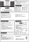
USER GUIDE
Wilhelm-Enssle-Str. 132-134, 73630 Remshalden, Germany
Tel.: int+49-71 81-40 98-0, Fax: int+49-71 81-40 98-30
http: //www.lrp-electronic.de
!
Dear customer,
Congratulations on choosing one of the world’s finest electronic speed controls. We have incorporated the
latest digital technology in your Quantum Sport series speed control in order to provide maximum
performance and reliability.
The following features give your new speed control the crucial advantage:
• Extended run-time
• Ultra High Performance using the latest SMD-MOS FETs
• Extra strong Brake-Power
• Super-light for improved chassis handling
• Adjustable Power-Control (APC)
• Small in size, fits anywhere + Plug-in and drive
• Short protection and safety of full warranty
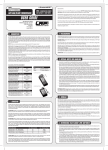
SPECIFICATION
Quantum
Sport
Voltage range / No. of cells
4.8-9.6 V / 4-8
Internal resistance
0.0015
Momentary load (1 sec)*
80 A
Brief load (30 sec)
40 A
Continuous load (5 min)
30 A
Recommended motor
14-36 turns
Receiver voltage
5.0 V
Max. receiver current (30 sec) 2.0 A
Continuous receiver current (5 min) 1.2 A
Quantum
Quantum
Super Sport
Pro Sport
4.8-9.6 V / 4-8 4.8-9.6 V / 4-8
0.00098
0.00073
115 A
155 A
60 A
80 A
40 A
55 A
12-36 turns
Over 7 turns
5.0 V
5.0 V
2.0 A
2.0 A
1.2 A
1.2 A
Quantum
Quantum
Sport
Super Sport
Pulse frequency
2100 Hz
2300 Hz
Adjustable Power Control (APC) yes
yes
Protective functions
yes
yes
Standard connector
yes
yes
Set-up procedure
Digital/push-button Digital/push-button
Battery recharge during braking yes
yes
Power-on pulse suppression yes
yes
Weight (excl. cables)
15.0 g
15.0 g
Case size (mm)
25.4x23.1x16 25.4x23.1x16
Quantum
Pro Sport
2500 Hz
yes
yes
yes
Digital/push-button
yes
yes
15.0 g
25.4x23.1x16
* The “Momentary load (1 sec)” figure corresponds to US manufacturers’ specifications: „ Continuous current at the temperature of 25°C “.
WARNING NOTES
• Important: never leave your RC model unattended when the
battery is connected. If a fault should occur the result might be a
fire in the model which could destroy anything else in the vicinity.
• The speed control and other electronic components must never
be allowed to contact water. Avoid operating the unit in rain.
If you are obliged to run in wet conditions, domestic paper towels
provide the best protection.
• If the motor is connected to the speed control you must not run
the motor by connecting a separate battery. This will wreck the
unit and invalidate the guarantee.
• Do not cut off the original plug, as this invalidates the guarantee.
• Take care to avoid incorrect connections and reverse polarity as
this will also cause damage to the unit. If you prefer different
INSTALLATION TIPS
•
•
•
•
•
connectors, fit a polarised connector system (plugs / sockets)
such as the LRP Hi-Amp (No. 6280); this does not invalidate your
guarantee.
Never allow the output stages (FETs) to contact any metal object
- short-circuit hazard.
Do not wrap your speed controller in foil; it is important to
provide a free flow of cooling air over it.
All cables and connections should be well insulated; short
circuits can easily wreck the controller.
Never alter the polarity of the receiver plug.
If you use more than 6 cells in the drive battery, the motor limit
rises by 2 turns for each additional cell.
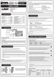
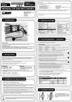
CONNECTIONS
Receiver lead
• Mount the speed control in the model using the double-sided foam tape supplied.
• Provide plenty of cooling openings in the bodywork; this increases the performance and extends
the life of all electronic components.
• Install the speed control in a location where it is protected from crash damage.
• The speed control should be installed in such a way that you have easy access to all connectors
and the set-up button.
• Ensure that there is an adequate distance (approx. 3 cm) between the speed control and power
cables and the receiver or receiver aerial. Avoid direct contact between all power system
components and the receiver or aerial, as this can cause interference. If you encounter interference
problems, re-position the components in the model.
• The aerial should be run vertically up and away from the receiver. Avoid contact with any parts
made of carbon fibre or metal. If the aerial is too long, don’t coil up the excess length. It is better to
cut it down to a length of about 35 cm. See also the instructions supplied with your radio control
system.
• IMPORTANT:
The heat-sink improves and safeguards the performance capacity
of your Quantum speed control when used close to its specified
limits. Use only the genuine LRP Quantum Sport series heat-sink,
Order No. 81456
Black-negative battery
Red-positive battery
FET-Servo lead
(Quantum Pro Sport only)
Yellow-positive motor
Blue-negative motor
On/Off switch
• Graupner, Ko-Propo, Futaba, Hitec and LRP Phaser receivers:
The LRP speed control is fitted with an LRP Multi-Con receiver lead which fits any of the above
receivers directly.
• Sanwa receivers:
Remove the black plastic moulding from the receiver cable and replace it with the plastic moulding
supplied (inscribed “AIR”) as follows:
• Replacing the plastic plug moulding:
Press in the metal lugs of the connector pins using a ball-point pen to disengage them; the wires
can then be withdrawn from the plastic housing. Check the polarity using the table below, and slip
the pins into the new plastic moulding until they snap into place.
Bend the metal lugs up again. Push the plug
into the new plastic moulding.
Check correct polarity carefully if changing connectors:
INSTALLATION
Receiver
Signal wire
Positive wire
Negative wire
Futaba
white
red
black
Graupner
orange
red
brown
Acoms
yellow
red
black
Sanwa
yellow
red
black
• First attach the heat-sinks (supplied) to the speed control, as described under “Installation tips”.
• Solder the suppressor capacitors to the motor.
• Remove the motor pinion, or ensure in some other way that the wheels of the model can rotate freely.
MOTOR SUPPRESSION:
Racing motor
Mabuchi motor
Schottky diode
Capacitor
Capacitor
Case
Capacitor
Install the speed control in the model.
Connect the speed control to the receiver (channel 2).
Check that the switch is set to “OFF”.
Connect the speed control to the motor. Note the colour code: yellow wire positive, blue
wire negative.
• If you are using a servo with an external FET lead, solder this in place (Quantum Pro-Sport only).
• Check all the wiring and connections before you connect the speed control to a drive battery.
Caution: incorrect polarity will wreck your speed control.
• The speed control is now ready to be set-up (see back page).
Schottky diode
diode
Schottky
Positive
•
•
•
•
Negative
Capacitor
Capacitor
The Schottky diode improves the efficiency of the speed control / motor combination and provides extra
protection to the brake FETs. Solder the diode in place as shown in the illustration. The white ring must
always face the positive motor terminal.
!
Caution: never use Schottky diodes in conjunction with a forward/
reverse speed control; they are for forward/brake units only!
Schottky-diode:
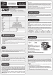
DESCRIPTION OF FEATURES
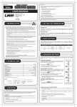
SET-UP PROCEDURE
In set-up mode the Quantum Sport-series speed control stores every step when you press the Set-up button.
All the settings are stored in the unit even when the speed control is subsequently disconnected from the
battery.
Start with the transmitter set-up procedure:
TRANSMITTER SETTINGS:
Set the basic functions on your transmitter as follows (if present):
High ATV, EPA
Low ATV, EPA, ATL
EXP, EXPO
SUB trim
TH trim, coast brake
Throttle reverse
(throttle travel)
(brake travel)
(exponential)
(neutral trim)
(servo reverse)
- maximum
- maximum
- start with 0
- centre
- centre
- any setting; must not be changed after
completion of set-up procedure.
Asymmetrical stick travel is possible (2/3 throttle - 1/3 brake)
Ultra High Performance using the latest SMD-MOS FETs
The internal resistance of these new FET transistors is about 2/3 lower.
Extended run-time
The lower internal resistance extends running times.
Ultra-powerful braking effect
The Quantum Sport series features an ultra-powerful fully proportional EMF brake which is nevertheless easy to
control on slippery surfaces. Energy is charged back into the drive battery every time you apply the brake.
Variable traction aid (APC)
Cars fitted with powerful “tuning” motors can easily run out of control when accelerating on slippery tracks. LRP’s
unique APC variable traction aid effectively prevents unwanted skidding and improves the car’s control on every
surface.
SETTINGS:
Maximum power
>Rotate control pot to right-hand stop (plus). At the maximum APC setting the
unit’s overload protection may be triggered, depending on the motor in use,
and in this case your speed control will switch off prematurely. If this should
happen, turn the control pot to the left by about 1/3 turn.
Slippery surfaces
>If your car spins, turn the control pot to the left (minus) until you have full
control of your car when accelerating.
Maximum APC setting
>If you select this setting to cope with an extremely slippery surface,
remember to turn the control pot back to the right-hand stop at the end of the
session, so that you can start with maximum power on the next track.
If your transmitter does not feature these set-up functions, it is already in “basic set-up” mode.
•
•
•
•
Check that the speed control is not connected to the drive battery, and is switched off.
Remove the motor pinion, or ensure in some other way that the wheels of the model are free to rotate.
Switch the transmitter on.
Set the transmitter throttle stick to neutral.
• Connect the speed control to the battery and swith the speed control on.
• Hold the set-up button pressed in for at least 3 seconds using the plastic screwdriver supplied.
• The set-up LED flashes green and indicates that you are in set-up mode.
•
•
•
•
•
Leave the throttle stick at neutral and press the set-up button.
The neutral setting is now stored.
Move the transmitter stick to full-throttle and press the set-up button with the stick still in this position.
The full-throttle setting is now stored.
Move the transmitter stick to full brake and press the set-up button with the stick still in this position.
The APC settings have no effect on the car’s maximum speed.
Short protection and safety of full warranty
The Quantum speed control’s integral Multi-Protection software provides a unique level of protection against short
circuit (motor), overload and overheating. If any of these overload situations occurs, the motor function is
switched off to protect the circuit, although the steering function is maintained. The bright red / green LED
flashes to indicate an overload situation.
Allow the speed control to cool down, and the throttle function will be switched on again automatically.
Check for the cause of the overload: is the motor too powerful? Is the motor pinion too large? Is the power train
stiff? Are you constantly switching from full power forward to full power in brake?
Small in size, fits anywhere + Plug-in and drive
The small size of Quantum speed controls allows them to be installed anywhere in the model. The factory-fitted
standard connectors provide an easy means of connecting it to battery and motor.
Super-light for improved chassis handling
The light weight of the Quantum speed control allows you to lower your model’s Centre of Gravity for improved
roadholding.
TROUBLE-SHOOTING GUIDE
• The set-up LED now glows green constantly.
• Your Quantum Sport series speed control is now completely set-up and ready to run.
• If you make a mistake during the set-up procedure, don’t worry: disconnect the battery for
about 10 seconds and start again from the first step.
• At the end of each run switch the speed control off, disconnect the battery, and only then
switch off the transmitter. At the start of each run switch on the transmitter first, then
connect the drive battery, and finally switch the speed control on.
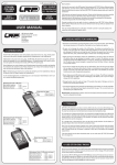
CHECKING THE FUNCTIONS:
You can check the following functions by watching the reaction of the LED:
FUNCTION
Neutral
Forward
Forward
Brake
Brake
Temperature protection
STATE
part-load
full-throttle
part-load
full brake
active
LED GLOWS
dull green
bright green
off
bright green
off
flashes bright green
REPAIR PROCEDURES/WARRANTY
In case of problems first check the trouble shooting guide or contact your hobby shop or LRP-importer. In
case of damage, repair fees are normally far below the recommended retail price of a new unit. Hobby
shops are not authorized to replace speed controls thought to be defective.
Warranty can only be accepted if it is claimed by the customer on the warranty sheet and the control sheet
and the original sales receipt are included.
For quick repair and return we definitely need your address, detailed description of the malfunction and the
original sales receipt. Repair may be refused without sales receipt.
To guarantee a proper repair, cut off or worn receiver plugs, wires and switches will be replaced and
charged in any case. Any speed control treated severely with silicone or anything similar inside, might not
be repairable.
WHAT SHALL I DO?
Speed controls sent in for repair that operate perfect normally will be charged with a service fee. Therefor
first check with the trouble shooting guide.
• Package your Speed-Control carefully.
LRP guarantees this speed control to be free from defects in materials or workmanship for 90 days from the
original date of purchase verified by sales receipt.
This warranty doesn’t cover: suitability for specific operation, incorrect installation, components worn by
use, application of reverse or improper voltage, shipping, tampering, misuse like any soldering inside the
unit, poor installation, replacing of wires on the board, connection to electrical components not mentioned
in the instructions, mechanical damage, immersion of water and cutting off the original wires, plugs,
connectors and switches.
Our warranty liability shall be limited to repairing the unit to our original specifications. Because we have no
control over the installation or use of this product, in no case shall our liability exceed the original cost of
this unit. We can't accept any liability for any damage resulting from using this product. By the act of
installing or operation this speed control, the user accepts all resulting liability.
• Send parcel to your national distributor.
• Distributor repairs/replaces the Speed Control.
• Shipment back to you usually by COD /cash on delivery), but is suject to your distributers
general policy.