1
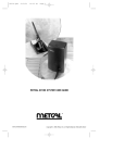
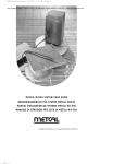
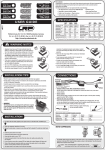
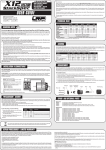
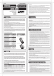
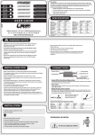
LA00104
ORDER NO.:
65800
© LRP electronic GmbH 2008
USER MANUAL
LRP electronic GmbH
Wilhelm-Enssle-Str. 132-134
73630 Remshalden
Germany
[email protected]
www.LRP.cc
1. WARNING NOTES
Dear Customer,
Thank you for your trust in this LRP product. By purchasing the LRP HighPower Soldering Station you have
choosen a high performance station full of new design features, such as:
• 90W High Power
• Adjustable AutoSleep and AutoShutdown function
• Advanced Digital, microprocessor controlled
• Large, blue backlit LCD Display
• Up to 480°C tip temperature
• Lightweight and compact design
• Wide range (100-240V) switching power supply
• Intuitive to use with 3 push buttons
Please read and understand these instructions completely before you use this product! With operating this
product, you accept the LRP warranty terms.
This manual contains important notes for safety, the use and the maintenance of this product. Thus protecting
yourself and avoid damages of the product. This manual shall be kept in a safe place. If another customer is
using this product, this manual shall be passed to him.
4. SETTING THE TEMPERATURE
Do not turn off the power supply while setting the temperature since the new value would not be stored.
No toy. Not suitable for children under 14 years. Keep the product out of the reach of children.
Pay close attention to the following points, as they can destroy the product and void your warranty. Non-observance of these points can lead to property damage, personal and severe injuries!
• Never leave the product unsupervised while it is switched on, in use or connected with a power
source. If a defect occurs, it could set fire to the product or the surroundings.
• When the power is on, the tip temperature is very high. Mishandling may lead to severe burns or fire.
Never touch the tip or the metal parts nearby while the power is switched on or has been switched
off shortly before.
• Do not replace handle or tips before turning the power off and let everything cool down to room
temperature.
• Never allow this product or other electronic components to come in contact with water, oil or fuels
or other electroconductive liquids, as these could contain minerals, which are harmful for electronic
circuits. If this happens, stop the use of your product immediately and let it dry carefully.
• Never cut off or modify the original plugs and original wires.
• Never open the product and never solder on the PCB or other components.
• Never use this product when the case is open, damaged or missing or when the product is wrapped
in a shrink-fit tube. This will reduce protection, may cause short circuits and damage the product.
• Always remove the battery from your product or disconnect the product from the power source, if
the product is not in use.
• During usage, the product has to be kept on a non-flammable, heat-resistant mat. Furthermore no
flammable or highly inflammable objects may be close to the product.
• In the case of damage, the product must not be used until it has been completely repaired.
TEMPERATURE UP:
Press button, the “Set Temp” will rise 1°C and the LCD will show the setting temperature. If you keep the
button pressed ~1sec, the setting temperature will rise quickly. Keep the button pressed until your desired
temperature has been reached.
TEMPERATURE DOWN:
Press button, the “Set Temp” will drop 1°C and the LCD will show the setting temperature. If you keep the
button pressed ~1sec, the setting temperature will drop rapidly. Keep the button pressed until your desired
temperature has been reached.
5. BASIC SETTINGS
Press and button at the same time while switching on the station to enter “Basic Settings”. The LCD shows
the current settings and you can alter them by using the / buttons. Here you can adjust tip size type and
if you want to use an alarm tone or not.
Working mode
Temperature range
Tip type
0
80°C - 480°C
Normal Tip
1
• The Powersupply has to be used in a well ventilated room.
• Do not manipulate the input power cords.
• The product is equipped with a 3-wire grounding plug and must be plugged into a 3-terminal grounded socket. Do not use an ungrounded socket.
80°C - 480°C
Big Tip
0
80°C - 480°C
Normal Tip
1
80°C - 480°C
Big Tip
Remark
is a alarming mark
• Do not rap the soldering iron against the work bench to shake off residual solder, otherwise the iron
will be damaged ny shocks.
• Replace only with genuine parts.
6. ADVANCED SETTINGS
• Do not use the Soldering Station for other applications except soldering.
The manufacturer can not be held responsible for damages, which are a result of non-observance
of the warning notes and security advices.
A) AUTOSLEEP – TIME SETTING:
The stations AutoSleep function will come effective if you don’t use the station
for the set AutoSleep time. It will go into sleep state and lower the tip temperature in order to extend tip life and safe energy.
2. TECHNICAL DATA
Input Voltage Range
100 - 240VAC
Power
90W
Output voltage
48V
Temperature Range
80°C - 480°C
AutoSleep - temperature range
50°C - 250°C
AutoSleep - time range
0 - 250min
0 - 250min
AutoShutdown - time range
Temperature Stability
±2°C (Without air flow and no load)
Tip to Ground Resistance
<2Ω
<2mV
Tip to Ground Potential
Heating Element
Electromagnetic heater
Handle Power Cord Length
1.4m
180mm
Length of Handle (Without Cord)
Outer Dimension
155 x 78 x 120mm
Weight (Without power cord)
1Kg
Above specifications and designs will be changed without notice.
DISPLAY:
heating indication
real temperature
From above “Basic Settings”, you can continue to “Advanced Settings” by pressing button and scroll through
to the different “Advanced Settings” by pressing further. All values can be adjusted by pressing the /
buttons.
setting temperature
alarming mark
3. OPERATION
IRON HOLDER AND SPONGE
Dampen the small cleaning sponge with water and squeeze it dry. Place it in the groove of the iron holder
base. Add a little water to the iron holder. The small sponge will absorb the water to keep the large sponge
above it wet all times. Dampen the large cleaning sponge and place it on the iron holder base.
CONNECTIONS
CAUTION: Be sure to turn off the power switch before connecting or disconnecting the soldering station
and iron. Failure to do so may damage the soldering station.
Attach the handle cords connector to the socket at the front of station. Take notice of the correct inserting position!
Place the handle in the MultiFunction Holder.
Insert the input power connector into the power socket.
Switch on the power supply.
SleepTime
The LCD indicates:
use / buttons to adjust the AutoSleep time (range 0-250min).
you disable AutoSleep function by selecting 000min.
B) AUTOSHUTDOWN – TIME SETTING:
As another safety feature, the station has a built in AutoShutdown which turns
power off completely if the station is not used for this period of time. This will
further extend tip life and avoids a running station for several hours for no use.
Basic Settings
Press
SleepTime
Press
OffTime
OffTime
The LCD indicates:
use / buttons to adjust the AutoShutdown time (range 0-250min).
you disable AutoShutdown function by selecting 000min.
the choosen AutoShutdown time should be longer than the choosen AutoSleep time, otherwise the soldering station will be turned off immediately
after it comes into sleep state.
C) AUTOSLEEP – TEMPERATURE SETTING:
Here you select to which temperature the station will regulate, once it is in AutoSleep state.
Press
Sleep
SetTemp
Press
Sleep
SetTemp
The LCD indicates:
use / buttons to adjust the AutoSleep temperature (range 50-250°C).
Setting temperature
IMPORTANT NOTES ABOUT “ADVANCED SETTINGS”:
1. The temperature will always regulate to lowest setting, no matter if working- or AutoSleep-Temperature
are set lower. As an example:
if AutoSleep is 200°C and the work temperature is 350°C, the station will regulate to 200°C in sleep
state.
if AutoSleep is 200°C and the work temperature is 150°C, the station will regulate to 150°C in sleep
state.
2. If soldering station is in AutoSleep state, there are three ways to resume soldering:
a) Take up the handle (there is a magnet positioned inside the holder for recognition).
b) Turn the power switch off and then turn on.
c) Press button
3. If soldering station is in AutoShutdown state, you need to turn switch off (leave for 3sec) and on again to
resume soldering!
4. The handle must be placed in the Multi Function holder to make use of AutoSleep and AutoShutdown
function!
7. USE / CARE AND MAINTENANCE
SOLDERING TIPS:
• Don’t apply pressure to the tip. More pressure does not equal more heat. To improve heat transfer, use
solder to form a thermal bridge between the tip and the solder joint.
• Select the tip which maximizes contact area between the tip and solder joint. Maximizing the contact area
transfers the heat more efficient and helps to produce high quality solder joints quickly.
• High soldering temperature can degrade the tip, therefore try to solder with the lowest possible temperature. The excellent thermal recovery characteristics ensure efficient and effective soldering even at low
temperatures. This also can protect the components, on which you solder, from thermal damage.
• When using the station continuously, be sure to remove all oxides on the tip at least once a week.
• Never leave the station running at high temperature for a long time with no use, because the tip will be
covered with oxide that can greatly reduce the tip’s heat conductivity.
• Wipe the tip and coat it with fresh solder after using. This helps to prevent tip oxidation.
• Clean the tip regularly with a cleaning sponge. Oxides and carbides, deriving from the solder and the flux,
can form impurities on the tip. This may result in bad soldering joints and reduction of the heating conductivity of the tip.
• Use fine tips only when necessary. The plating on fine tips is less durable than the plating on the larger tip.
• Do not bend the tip, as this may cause the plating to crack and shorten the tip’s life.
• Use the minimum activation flux necessary to do the job. Higher activation flux is more corrosive to the tip
plating.
RENNEW AND DENNTINED TIP:
Why does a detinned tip fail to work? A detinned tip is one not wetted with solder. This exposes the plating to
oxidation and degrades the heat transfer efficiency of the tip.
REPAIR PROCEDURES /
LIMITED WARRANTY
All products from LRP electronic GmbH (hereinafter called “LRP”) are manufactured according to the highest
quality standards. LRP guarantees this product to be free from defects in materials or workmanship for 90
days (non-european countris only) from the original date of purchase verified by sales receipt. This limited
warranty doesn’t cover defects, which are a result of misuse, improper maintenance, outside interference or
mechanical damage.
This applies among other things on:
• Soldering station disassembly by customer
• Any modification of the Soldering station done by the customer
• Humidity/Water inside the Soldering station
• Case opened by customer
• Manipulated input/output wires
To eliminate all other possibilities or improper handling, first check all other components in your model and the
trouble shooting guide, if available, before you send in this product for repair. If products are sent in for repair,
which do operate perfectly, we have to charge a service fee according to our pricelist.
With sending in this product, the customer has to advise LRP if the product should be repaired in either case. If
there is neither a warranty nor guarantee claim, the inspection of the product and the repairs, if necessary, in
either case will be charged with a fee at the customers expense according to our price list. A proof of purchase
including date of purchase needs to be included. Otherwise, no warranty can be granted. For quick repair- and
return service, add your address and detailed description of the malfunction.
DETINNING IS CAUSED BY: Failure to keep the tip coating with fresh solder while not in using. High temperatures. Wiping the tip on dirty or dry sponges or rags. Impurities in the solder, iron plating, or on the surfaces
to be soldered.
If LRP no longer manufactures a returned defective product and we are unable to service it, we shall provide you
with a product that has at least the same value from one of the successor series.
RENEW
Remove the tip from the handle after the tip cooling down.
Remove the dirty and oxides from the tip with 80-grit abrasive polyurethane foam stock or a 100-grit emery.
Wrap the stannum including rosin (ø 0.8mm or larger) around the newly exposed iron surface, insert the tip
into the handle, and turn on the power switch.
The specifications like weight, size and others should be seen as guide values. Due to ongoing technical improvements, which are done in the interest of the product, LRP does not take any responsibility for the accuracy
of these specs.
With LRP 25-Years Warranty products, the warranty terms on the LRP 25-Years Warranty card do also apply.
The legal warranty claims, which arose originally when the product was purchased, shall remain unaffected.
NOTE´S:
• Never file the tip to remove oxide. Proper daily care can prevent the tip from detinned.
• If the tip is deformed or heavily eroded, replace it with a new one
SPARE PARTS:
Only use genuine LRP spare parts!
• #65802 Soldering Tip 5.0mm
• #65803 Soldering Tip 1.2mm
• #65804 Handle Assembly
8. ERROR MESSAGES
Various error messages will be displayed when there is something wrong with the device.
SENSOR ERROR: if there is a malfunction in the sensor or anywhere in the sensor circuit, “S-E” will
be displayed and the power supply to the soldering iron will be cut off.
HEATER ERROR: If there is something wrong with the heating element, “H-E” will be displayed and
the power supply to the soldering iron will be cut off.
In both cases you should replace the handle, there is a spare handle available with # 65804
REPLACE THE FUSE:
Turn off the power switch and then pull out the fuse plug in the power plug.
Open the fuse cover board and take out the broken fuse.
Replace a new fuse and put back the fuse cover board in place.
LRP-Distributor-Service:
• Package your product carefully and include sales receipt and detailed description of malfunction.
• Send parcel to your national LRP distributor.
• Distributor repairs or exchanges the product.
• Shipment back to you usually by COD (cash on delivery), but this is subject to your national LRP distributor‘s
general policy.
The crossed-out wheeled bin means that within the European Union the product must be
taken to seperate collection at the product end-of-life. Do not dispose of these products as
unsorted municipal waste.