1
USB-Blaster II Download Cable User Guide
USB-Blaster II Download Cable
User Guide
101 Innovation Drive
San Jose, CA 95134
www.altera.com
UG-01150-1.2
P25-36700-02
Feedback Subscribe
© 2014 Altera Corporation. All rights reserved. ALTERA, ARRIA, CYCLONE, HARDCOPY, MAX, MEGACORE, NIOS, QUARTUS and STRATIX words and logos
are trademarks of Altera Corporation and registered in the U.S. Patent and Trademark Office and in other countries. All other words and logos identified as
trademarks or service marks are the property of their respective holders as described at www.altera.com/common/legal.html. Altera warrants performance of its
semiconductor products to current specifications in accordance with Altera's standard warranty, but reserves the right to make changes to any products and
services at any time without notice. Altera assumes no responsibility or liability arising out of the application or use of any information, product, or service
described herein except as expressly agreed to in writing by Altera. Altera customers are advised to obtain the latest version of device specifications before relying
on any published information and before placing orders for products or services.
October 2014
Altera Corporation
ISO
9001:2008
Registered
USB-Blaster II Download Cable
User Guide
Contents
Chapter 1. Setting Up the USB-Blaster II Download Cable
Supported Devices and Systems . . . . . . . . . . . . . . . . . . . . . . . . . . . . . . . . . . . . . . . . . . . . . . . . . . . . . . . . . . . 1–1
Power Source Requirements . . . . . . . . . . . . . . . . . . . . . . . . . . . . . . . . . . . . . . . . . . . . . . . . . . . . . . . . . . . . . . 1–1
Software Requirements and Support . . . . . . . . . . . . . . . . . . . . . . . . . . . . . . . . . . . . . . . . . . . . . . . . . . . . . . . 1–1
Installing the Download Cable for Configuration or Programming . . . . . . . . . . . . . . . . . . . . . . . . . . . . . 1–2
Installing the USB-Blaster II Driver on Windows 7/8 Systems . . . . . . . . . . . . . . . . . . . . . . . . . . . . . . . . . 1–3
Installing the USB-Blaster II Driver on Linux Systems . . . . . . . . . . . . . . . . . . . . . . . . . . . . . . . . . . . . . . . . 1–3
Installing the USB-Blaster II Driver on Windows XP Systems . . . . . . . . . . . . . . . . . . . . . . . . . . . . . . . . . . 1–4
Setting Up the USB-Blaster II Hardware with the Quartus II Software . . . . . . . . . . . . . . . . . . . . . . . . . . 1–4
Chapter 2. USB-Blaster II Download Cable Specifications
Voltage Requirements . . . . . . . . . . . . . . . . . . . . . . . . . . . . . . . . . . . . . . . . . . . . . . . . . . . . . . . . . . . . . . . . . . . . 2–1
Cable-to-Board Connection . . . . . . . . . . . . . . . . . . . . . . . . . . . . . . . . . . . . . . . . . . . . . . . . . . . . . . . . . . . . . . . 2–1
USB-Blaster II Plug Connection . . . . . . . . . . . . . . . . . . . . . . . . . . . . . . . . . . . . . . . . . . . . . . . . . . . . . . . . . . . . 2–2
10-Pin Female Plug Signal Names and Programming Modes . . . . . . . . . . . . . . . . . . . . . . . . . . . . . . . . . . 2–3
Circuit Board Header Connection . . . . . . . . . . . . . . . . . . . . . . . . . . . . . . . . . . . . . . . . . . . . . . . . . . . . . . . . . 2–3
Operating Conditions . . . . . . . . . . . . . . . . . . . . . . . . . . . . . . . . . . . . . . . . . . . . . . . . . . . . . . . . . . . . . . . . . . . . 2–4
JTAG Timing Constraints and Waveforms . . . . . . . . . . . . . . . . . . . . . . . . . . . . . . . . . . . . . . . . . . . . . . . . . . 2–5
Changing the TCK Frequency . . . . . . . . . . . . . . . . . . . . . . . . . . . . . . . . . . . . . . . . . . . . . . . . . . . . . . . . . . . . . 2–7
Additional Information
Document Revision History . . . . . . . . . . . . . . . . . . . . . . . . . . . . . . . . . . . . . . . . . . . . . . . . . . . . . . . . . . .
How to Contact Altera . . . . . . . . . . . . . . . . . . . . . . . . . . . . . . . . . . . . . . . . . . . . . . . . . . . . . . . . . . . . . . . .
Typographic Conventions . . . . . . . . . . . . . . . . . . . . . . . . . . . . . . . . . . . . . . . . . . . . . . . . . . . . . . . . . . . . .
Certification Statements . . . . . . . . . . . . . . . . . . . . . . . . . . . . . . . . . . . . . . . . . . . . . . . . . . . . . . . . . . . . . . .
Statement of China-RoHS Compliance . . . . . . . . . . . . . . . . . . . . . . . . . . . . . . . . . . . . . . . . . . . . . . . .
USB 2.0 Certification . . . . . . . . . . . . . . . . . . . . . . . . . . . . . . . . . . . . . . . . . . . . . . . . . . . . . . . . . . . . . . .
October 2014
Altera Corporation
Info–1
Info–1
Info–2
Info–3
Info–3
Info–3
USB-Blaster II Download Cable
User Guide
iv
USB-Blaster II Download Cable
User Guide
Contents
October 2014 Altera Corporation
1. Setting Up the USB-Blaster II Download
Cable
The USB-Blaster™ II download cable interfaces a USB port on a host computer to an
Altera® FPGA mounted on a printed circuit board. The download cable sends data
from the PC to a standard 10-pin header connected to the FPGA. You can use the
download cable for the following:
■
Iteratively download configuration data to a system during prototyping
■
Program data into the system during production
■
Advanced Encryption Standard (AES) key and fuse programming
Supported Devices and Systems
You can use the USB-Blaster II download cable to download configuration data to the
following Altera devices:
■
Stratix® series FPGAs
■
Cyclone® series FPGAs
■
MAX® series CPLDs
■
Arria® series FPGAs
You can perform in-system programming of the following devices:
■
EPC4, EPC8, and EPC16 enhanced configuration devices
■
EPCS1, EPCS4, EPCS16, EPCS64, and EPCS/Q128, EPCQ256, and EPCQ512 serial
configuration devices
The download cable supports target systems using the following:
■
5.0-V TTL, 3.3-V LVTTL/LVCMOS
■
Single-ended I/O standards from 1.5 V to 3.3 V
Power Source Requirements
■
5.0 V from the USB cable
■
Between 1.5 V and 5.0 V from the target circuit board
Software Requirements and Support
■
Windows 7/8 (32-bit and 64-bit)
■
Windows XP (32-bit and 64-bit)
■
Windows Server 2008 R2 (64-bit)
■
Linux platforms such as Red Hat Enterprise 5
Use the Quartus® II software version 14.0 or later to configure your device.
October 2014
Altera Corporation
USB-Blaster II Download Cable
User Guide
1–2
Chapter 1: Setting Up the USB-Blaster II Download Cable
Installing the Download Cable for Configuration or Programming
1
Quartus II software version 13.1 supports most of the download cable’s capabilities. If
you use this version, install the latest patch for full compatibility.
The download cable also supports the following tools:
■
Quartus II Programmer (and stand-alone version)
■
Quartus II SignalTap® II Logic Analyzer (and stand-alone version)
■
JTAG and debug tools supported by the JTAG Server. For example:
■
System Console
■
Nios II debugger
■
ARM DS-5 debugger
Installing the Download Cable for Configuration or Programming
1. Disconnect the power cable from the circuit board.
2. Connect the download cable to the USB port on your computer and to the
USB-Blaster II port.
3. Connect the download cable to the 10-pin header on the device board.
4. Reconnect the power cable to reapply power to the circuit board.
.
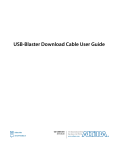
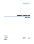
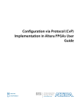
Figure 1–1. The USB-Blaster II Download Cable
10-pin Female Connector
(Connects to target printed
circuit board 10-pin male header.)
LED Color
Off
Blue
Teal
Green
Green flickering
Magenta blinking
Description
Not connected or suspended
Connected at 12MHz (USB full speed)
Connected at 480MHz (USB high speed)
JTAG port open, idle
JTAG port open, active
Set by user to identify a cable (1)
(1)
To identify a particular cable, use the following JTAG command:
jtagconfig --setparam <cable number> Identify <1 = on, 0 = off>
1
For plug and header dimensions, pin names, and operating conditions, see Chapter 2,
USB-Blaster II Download Cable Specifications.
USB-Blaster II Download Cable
User Guide
October 2014 Altera Corporation
Chapter 1: Setting Up the USB-Blaster II Download Cable
Installing the USB-Blaster II Driver on Windows 7/8 Systems
1–3
Installing the USB-Blaster II Driver on Windows 7/8 Systems
You must have system administration (administrator) privileges to install the
USB-Blaster II download cable drivers.
The download cable drivers are included in the Quartus II software installation.
Before you begin the installation, verify that the USB-Blaster II driver is located in
your directory: \<Quartus II system directory>\drivers\usb-blaster-ii.
1. Connect the download cable to your computer’s USB port.
When plugged in for the first time, a message appears stating Device driver
software was not successfully installed.
2. From the Windows Device Manager, locate Other devices and right-click the top
USB-BlasterII.
You need to install drivers for each interface: one for the JTAG interface and one
for the System Console interface.
3. On the right-click menu, click Update Driver Software. The Update Driver
Software - USB BlasterII dialog appears.
4. Click Browse my computer for driver software to continue.
5. Click Browse… and browse to the location of the driver on your system:
\<Quartus II system directory>\drivers\usb-blaster-ii. Click OK.
6. Click Next to install the driver.
7. Click Install when asked if you want to install.
You should now have a JTAG cable showing in the Device Manager.
8. Now, install the driver for the other interface. Go back to step 2 and repeat the
process for the other USB-BlasterII device.
When you are finished, you will have added Altera USB-Blast II (JTAG interface)
under JTAG cables.
Installing the USB-Blaster II Driver on Linux Systems
For Linux, the USB-Blaster II download cable supports Red Hat Enterprise 5 and
above.
October 2014
Altera Corporation
USB-Blaster II Download Cable
User Guide
1–4
Chapter 1: Setting Up the USB-Blaster II Download Cable
Installing the USB-Blaster II Driver on Windows XP Systems
To access the download cable, the Quartus II software uses the built-in Red Hat USB
drivers, the USB file system (usbfs). By default, root is the only user allowed to use
usbfs. You must have system administration (root) privileges to configure the
USB-Blaster II download cable drivers.
1. Create a file named /etc/udev/rules.d/51-usbblaster.rules and add the following
lines to it. (The .rules file may already exist if you have installed an earlier
USB-Blaster version.)
# USB-Blaster II
BUS=="usb", SYSFS{idVendor}=="09fb", SYSFS{idProduct}=="6010", MODE="0666"
BUS=="usb", SYSFS{idVendor}=="09fb", SYSFS{idProduct}=="6810", MODE="0666"
c
There should be only three lines in this file, one starting with a comment
and two starting with BUS. Do not add extra line breaks to the .rules file.
2. Complete your installation by setting up the programming hardware in the
Quartus II software. Go to the “Setting Up the USB-Blaster II Hardware with the
Quartus II Software” section on the following page.
f For more information about USB-Blaster II driver installation, refer to the
Cable and Adapter Drivers web page
http://www.altera.com/download/drivers/dri-index.html.
Installing the USB-Blaster II Driver on Windows XP Systems
You must have system administration (administrator) privileges to install the
USB-Blaster II download cable driver.
The download cable drivers are included in the Quartus II software installation.
Before you begin the installation, verify that the USB-Blaster II driver is located in
your directory: \<Quartus II system directory>\drivers\usb-blaster-ii.
f Follow the installation procedure found at this web page:
http://www.altera.com/download/drivers/usb-blaster/dri-usb-blasterxp.html#note.
Setting Up the USB-Blaster II Hardware with the Quartus II Software
1. Start the Quartus II software.
2. From the Tools menu, click Programmer.
3. Click Hardware Setup.
4. Click the Hardware Settings tab.
5. From the Currently selected hardware list, select USB-Blaster II.
6. Click Close.
7. In the Mode list, choose an appropriate programming mode. Table 1–1 on
page 1–5 describes each mode.
USB-Blaster II Download Cable
User Guide
October 2014 Altera Corporation
Chapter 1: Setting Up the USB-Blaster II Download Cable
Setting Up the USB-Blaster II Hardware with the Quartus II Software
1–5
Table 1–1. Programming Modes
Mode
Mode Description
Joint Test Action
Group (JTAG)
Programs or configures all Altera devices supported by Quartus II
software via JTAG programming.
In-Socket
Programming
Not supported by the USB-Blaster II.
Passive Serial
Programming
Configures all Altera devices supported by Quartus II software excluding
enhanced configuration devices (EPC) and serial configuration devices
(EPCS/Q).
Active Serial
Programming
Programs a single EPCS1, EPCS4, EPCS16, EPCS64, EPCS/Q128,
EPCQ256, and EPCQ512 device.
f For detailed help on using the Quartus II Programmer, refer to the Quartus II
Handbook, http://www.altera.com/literature/hb/qts/quartusii_handbook.pdf.
October 2014
Altera Corporation
USB-Blaster II Download Cable
User Guide
1–6
USB-Blaster II Download Cable
User Guide
Chapter 1: Setting Up the USB-Blaster II Download Cable
Setting Up the USB-Blaster II Hardware with the Quartus II Software
October 2014 Altera Corporation
2. USB-Blaster II Download Cable
Specifications
Voltage Requirements
The USB-Blaster II VCC(TRGT) pin must be connected to a specific voltage for the
device being programmed. Connect pull-up resistors to the same power supply as the
USB-Blaster II: VCC(TRGT).
Table 2–1. USB-Blaster II VCC(TRGT) Pin Voltage Requirements
Device Family
USB-Blaster II VCC Voltage Required
Arria GX
As specified by VCCSEL
Arria II GX
As specified by VCCPD or VCCIO of Bank 8C
Arria V
As specified by VCCPD Bank 3A
Cyclone III
As specified by VCCA or VCCIO
Cyclone IV
As specified by VCCIO. Bank 9 for Cyclone IV GX and Bank 1 for
Cyclone IV E devices.
Cyclone V
As specified by VCCPD Bank 3A
EPC4, EPC8, EPC16
3.3 V
EPCS1, EPCS4, EPCS16, EPCS64,
EPCS128
3.3 V
EPCS/Q16, EPCS/Q64,
EPCS/Q128, EPCQ256, EPCQ512
3.3 V
MAX II, MAX V
As specified by VCCIO of Bank 1
Stratix II, Stratix II GX
As specified by VCCSEL
Stratix III, Stratix IV
As specified by VCCPGM or VCCPD
Stratix V
As specified by VCCPD Bank 3A
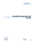
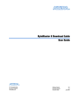
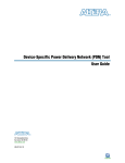
Cable-to-Board Connection
A standard USB cable connects to the USB port on the device.
Figure 2–1. USB-Blaster II Download Cable Block Diagram
EPM570M100C5
VCC
USB
Receptacle
USB Interface
Chip
I/O
LVDS
Drivers/Receivers
LVDS
Cabling
Voltage
Translator Circuitry
Pin 1
10-Pin
Female Plug
VCC (TRGT)
I/O
I/Os
I/O
I/O
I/Os
I/O
I/O
I/O
October 2014
Altera Corporation
USB-Blaster II Download Cable
User Guide
2–2
Chapter 2: USB-Blaster II Download Cable Specifications
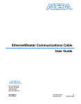
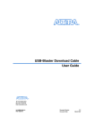
USB-Blaster II Plug Connection
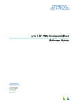
USB-Blaster II Plug Connection
The 10-pin female plug connects to a 10-pin male header on the circuit board
containing the target device.
Figure 2–2. USB-Blaster II Dimension - Inches and Millimeters
0.70 (17.8) Typ.
1.33 (33.8) Typ.
Cable Length: 8.77 (222.8) Typ.
2.5 (63.5) Typ.
0.81 (20.6) Typ.
1.63 (41.4) Typ.
Figure 2–3. USB-Blaster II 10-Pin Female Plug Dimensions - Inches & Millimeters
0.37 (9.4)Typ.
10
8
6
4
2
9
7
5
3
1
0.24 (6.1)Typ.
0.04 (1.0)Typ.
.025
.10 (2.5)Sq. 0.15 (3.8)Typ. (.63)Sq.
0.70 (17.8)Typ.
USB-Blaster II Download Cable
User Guide
October 2014 Altera Corporation
Chapter 2: USB-Blaster II Download Cable Specifications
10-Pin Female Plug Signal Names and Programming Modes
2–3
10-Pin Female Plug Signal Names and Programming Modes
Table 2–2. 10-Pin II Female Plug Signal Names and Programming Modes
Active Serial (AS) Mode
Passive Serial (PS) Mode
JTAG Mode
Pin
Signal Name
Description
Signal Name
Description
Signal Name
Description
1
DCLK
Clock signal
DCLK
Clock signal
TCK
Clock signal
2
GND
Signal ground
GND
Signal ground
GND
Signal ground
3
CONF_DONE
Configuration done
CONF_DONE
Configuration done
TDO
Data from device
4
VCC(TRGT) Target power supply
VCC(TRGT)
Target power
supply
VCC(TRGT)
Target power supply
5
nCONFIG
Configuration
control
nCONFIG
Configuration
control
TMS
JTAG state machine
control
6
nCE
Cyclone chip enable
—
No connect
PROC_RST (1)
Hard processor reset
7
DATAOUT
Active serial data
out
nSTATUS
Configuration
status
—
No connect
8
nCS
Serial configuration
device chip select
—
No connect
—
No connect
9
ASDI
Active serial data in
DATA0
Data to device
TDI
Data to device
10
GND
Signal ground
GND
Signal ground
GND
Signal ground
Note to Table 2–2:
(1) Use pin 6 for a hard processor reset under JTAG mode.
Circuit Board Header Connection
The 10-pin male header, which connects to the download cable's 10-pin female plug,
has two rows of five pins. The pins are connected to the device’s programming or
configuration pins.
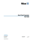
c If the header connection on the circuit board is a male receptacle, it must have a key
notch. Without a key notch, the 10-pin female plug will not connect. The following
figure shows a typical 10-pin male header with a key notch.
Figure 2–4. 10-Pin Male Header Dimensions - Inches and Millimeters
Top View
Side View
0.100 (2.540)
0.100
0.025 (0.635) Sq.
0.235 (5.969)
A key notch is required.
October 2014
Altera Corporation
USB-Blaster II Download Cable
User Guide
2–4
Chapter 2: USB-Blaster II Download Cable Specifications
Operating Conditions
1
Although a 10-pin surface mount header can be used for the download cable, Altera
recommends using a through-hole connector. Through-hole connectors hold up better
under the repeated insertion and removal.
Operating Conditions
The following tables summarize the maximum ratings, recommended operating
conditions, and DC operating conditions for the USB-Blaster II cable.
Table 2–3. USB-Blaster II Cable Absolute Maximum Ratings
Symbol
Parameter
Conditions
Min
Max
Unit
VCC(TRGT)
Target supply voltage
With respect to
ground
–0.5
6.5
V
VCC(USB)
USB supply voltage
With respect to
ground
–0.5
6.0
V
Target side input current
Pin 7
–100.0
100.0
mA
USB supply current
VBUS
—
200.0
mA
Target side output current
Pins: 1, 5, 6, 8, 9
–50.0
50.0
mA
II
II(USB)
Io
Table 2–4. USB-Blaster II Cable Recommended Operating Conditions
Symbol
Parameter
VCC(TRGT)
Conditions
Min
Max
Unit
Target supply voltage,
5.0-V operation
—
4.75
5.25
V
Target supply voltage,
3.3-V operation
—
3.0
3.6
V
Target supply voltage,
2.5-V operation
—
2.375
2.625
V
Target supply voltage,
1.8-V operation
—
1.71
1.89
V
Target supply voltage,
1.5-V operation
—
1.43
1.57
V
Table 2–5. USB-Blaster II Cable DC Operating Conditions (Part 1 of 2)
Symbol
VIH
VIL
USB-Blaster II Download Cable
User Guide
Parameter
Conditions
Min
Max
Unit
0.7 x
VCC(TRGT)
—
V
VCC(TRGT) < 2.0 V
0.65 x
VCC(TRGT)
—
V
VCC(TRGT) >= 2.0 V
—
0.3 x
VCC(TRGT)
V
VCC(TRGT) < 2.0 V
—
0.2 x
VCC(TRGT)
V
High-level input voltage VCC(TRGT) >= 2.0 V
Low-level input voltage
October 2014 Altera Corporation
Chapter 2: USB-Blaster II Download Cable Specifications
JTAG Timing Constraints and Waveforms
2–5
Table 2–5. USB-Blaster II Cable DC Operating Conditions (Part 2 of 2)
Symbol
VOH
VOL
ICC(TRGT)
Parameter
Conditions
Min
Max
Unit
5.0-V high-level output
voltage
VCC(TRGT) = 4.5 V, IOH = -32 mA
3.8
—
V
3.3-V high-level output
voltage
VCC(TRGT) = 3.0 V, IOH = -24 mA
2.4
—
V
2.5-V high-level output
voltage
VCC(TRGT) = 2.3 V, IOH = -12 mA
1.9
—
V
1.8-V high-level output
voltage
VCC(TRGT) = 1.65 V, IOH = -8 mA
1.2
—
V
1.5-V high-level output
voltage
VCC(TRGT) = 1.4 V, IOH = -6 mA
1.0
—
V
5.0-V low-level output
voltage
VCC(TRGT) = 4.5 V, IOL = 32 mA
—
0.55
V
3.3-V low-level output
voltage
VCC(TRGT) = 3.0 V, IOL = 24 mA
—
0.55
V
2.5-V low-level output
voltage
VCC(TRGT) = 2.3 V, IOL = 12 mA
—
0.3
V
1.8-V low-level output
voltage
VCC(TRGT) = 1.65 V, IOL = 8 mA
—
0.45
V
1.5-V low-level output
voltage
VCC(TRGT) = 1.4 V, IOL = 6 mA
—
0.3
V
Operating current (No
Load)
VCC(TRGT) = 5.5 V
—
316
uA
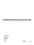
JTAG Timing Constraints and Waveforms
Figure 2–5. Timing Waveform for JTAG Signals (From Target Device Perspective)
tJCP
tJCH
tJCL
TCK
JTAG Output
tJPCO
TDO
TCK
JTAG Inputs
tJPSU_TMS
tJPH
TMS
tJPSU_TDI
TDI
October 2014
Altera Corporation
USB-Blaster II Download Cable
User Guide
2–6
Chapter 2: USB-Blaster II Download Cable Specifications
JTAG Timing Constraints and Waveforms
To use the USB-Blaster II at the maximum capability (24 MHz), meet the timing
constraints (Table 2–6) for the target device.
The timing constraints require that you consider device specifications as well as trace
propagation delays. If you do not follow the recommended constraints, you might
encounter timing issues at 24 MHz. If the target design cannot meet these constraints,
reduce the possibility of timing issues by slowing the TCK frequency. See “Changing
the TCK Frequency” on page 2–7 for instructions on running the USB-Blaster II at a
slower speed.
Table 2–6. JTAG Timing Constraints for the Target Device
Symbol
1
Parameter
Min
Max
Unit
tJCP
TCK clock period
41.67
—
ns
tJCH
TCK clock high time
20.83
—
ns
tJCL
TCK clock low time
20.83
—
ns
tJPCO
JTAG port clock to JTAG Header output
—
5.46 (2.5 V)
2.66 (1.5 V)
ns
tJPSU_TDI
JTAG port setup time (TDI)
—
24.42
ns
tJPSU_TMS JTAG port setup time (TMS)
—
26.43
ns
tJPH
—
17.25
ns
JTAG port hold time
The simulated timing is based on a slow timing model, which is a worst-case scenario
environment.
f For device-specific JTAG timing information, refer to the related device data sheet
available from the http://www.altera.com/literature/lit-index.html web page.
USB-Blaster II Download Cable
User Guide
October 2014 Altera Corporation
Chapter 2: USB-Blaster II Download Cable Specifications
Changing the TCK Frequency
2–7
Changing the TCK Frequency
The USB-Blaster II download cable has a default TCK frequency of 24 MHz. Where
signal integrity and timing prevents operating at 24 MHz, change the TCK frequency of
the USB-Blaster II:
1. Open the command line interface with the Quartus II bin directory in your path
(for example, C:\altera\14.0\quartus\bin64).
2. Type the following command to change the TCK frequency:
jtagconfig --setparam <cable number> JtagClock <frequency><unit prefix>
Where:
■
<cable number> is the USB-Blaster II cable to be modified.
■
<frequency> is the desired TCK frequency. Use one the following supported
rates:
■
■
24 MHz
■
16 MHz
■
6 MHz
■
24/n MHz (between 10 kHz and 6 MHz, where n represents an integer
value number)
<unit prefix> is the unit prefix for the frequency (e.g., M for MHz).
Example for setting TCK maximum frequency to 6 MHz:
jtagconfig --setparam 1 JtagClock 6M
October 2014
Altera Corporation
USB-Blaster II Download Cable
User Guide
2–8
USB-Blaster II Download Cable
User Guide
Chapter 2: USB-Blaster II Download Cable Specifications
Changing the TCK Frequency
October 2014 Altera Corporation
Additional Information
Document Revision History
Date
Version
Changes
Added that the USB-II download cable supports Advanced Encryption Standard (AES) key
and fuse programming.
September 2014
1.2
Added magenta LED color to Figure 1-1 supporting multiple cable use.
Clarified a cross reference pointing to device-specific JTAG timing information.
Added LED color table to Figure 1-1.
June 2014
1.1
Added “JTAG Timing Constraints and Waveforms” section.
Added “Changing the TCK Frequency” section.
January 2014
1.0
Initial release.
How to Contact Altera
To locate the most up-to-date information about Altera products, refer to the
following table.
Contact (1)
Technical support
Technical training
Product literature
Contact Method
Address
Website
www.altera.com/support
Website
www.altera.com/training
Email
Website
[email protected]
www.altera.com/literature
Nontechnical support (general)
Email
[email protected]
(software licensing)
Email
[email protected]
Note to Table:
(1) You can also contact your local Altera sales office or sales representative.
October 2014
Altera Corporation
USB-Blaster II Download Cable
User Guide
Info–2
Additional Information
Typographic Conventions
Typographic Conventions
Visual Cue
Meaning
Bold Type with Initial Capital
Letters
Indicate command names, dialog box titles, dialog box options, and other GUI
labels. For example, Save As dialog box. For GUI elements, capitalization matches
the GUI.
bold type
Indicates directory names, project names, disk drive names, file names, file name
extensions, software utility names, and GUI labels. For example, \qdesigns
directory, D: drive, and chiptrip.gdf file.
Italic Type with Initial Capital Letters
Indicate document titles. For example, Stratix IV Design Guidelines.
Indicates variables. For example, n + 1.
italic type
Variable names are enclosed in angle brackets (< >). For example, <file name> and
<project name>.pof file.
Initial Capital Letters
Indicate keyboard keys and menu names. For example, the Delete key and the
Options menu.
“Subheading Title”
Quotation marks indicate references to sections in a document and titles of
Quartus II Help topics. For example, “Typographic Conventions.”
Indicates signal, port, register, bit, block, and primitive names. For example, data1,
tdi, and input. The suffix n denotes an active-low signal. For example, resetn.
Courier type
Indicates command line commands and anything that must be typed exactly as it
appears. For example, c:\qdesigns\tutorial\chiptrip.gdf.
Also indicates sections of an actual file, such as a Report File, references to parts of
files (for example, the AHDL keyword SUBDESIGN), and logic function names (for
example, TRI).
r
An angled arrow instructs you to press the Enter key.
1., 2., 3., and
a., b., c., and so on
Numbered steps indicate a list of items when the sequence of the items is important,
such as the steps listed in a procedure.
■ ■
Bullets indicate a list of items when the sequence of the items is not important.
■
1
The hand points to information that requires special attention.
h
The question mark directs you to a software help system with related information.
f
The feet direct you to another document or website with related information.
m
The multimedia icon directs you to a related multimedia presentation.
c
A caution calls attention to a condition or possible situation that can damage or
destroy the product or your work.
w
A warning calls attention to a condition or possible situation that can cause you
injury.
The envelope links to the Email Subscription Management Center page of the Altera
website, where you can sign up to receive update notifications for Altera documents.
The feedback icon allows you to submit feedback to Altera about the document.
Methods for collecting feedback vary as appropriate for each document.
USB-Blaster II Download Cable
User Guide
October 2014 Altera Corporation
Additional Information
Certification Statements
Info–3
Certification Statements
Statement of China-RoHS Compliance
Table Info–1 lists hazardous substances included with the USB-Blaster download
cable.
Table Info–1. Table of Hazardous Substances’ Name and Concentration
(1)
Hexavalent
Chromium Mercury Polybrominated
(Cr6+)
(Hg)
biphenyls (PBB)
Polybrominated
diphenyl Ethers
(PBDE)
Lead
(Pb)
Cadmium
(Cd)
Electronic
Components
0
0
0
0
0
0
Populated
Circuit Board
0
0
0
0
0
0
Manufacturing
Process
0
0
0
0
0
0
Packing
0
0
0
0
0
0
Part Name
Note to Table Info–1:
(1) 0 indicates that the concentration of the hazardous substance in all homogeneous materials in the parts is below
the relevant threshold of the SJ/T11363-2006 standard.
USB 2.0 Certification
This product is USB 2.0 certified.
October 2014
Altera Corporation
USB-Blaster II Download Cable
User Guide
Info–4
USB-Blaster II Download Cable
User Guide
Additional Information
Certification Statements
October 2014 Altera Corporation