1
USB-Blaster Download Cable User Guide
Subscribe
Send Feedback
UG-USB81204
2015.08.20
101 Innovation Drive
San Jose, CA 95134
www.altera.com
TOC-2
Contents
Introduction to USB-Blaster Download Cable...................................................1-1
USB-Blaster Revision...................................................................................................................................1-1
Supported Devices and Host Systems....................................................................................................... 1-1
Specifications for USB-Blaster Download Cable................................................2-1
Block Diagram and Dimension..................................................................................................................2-1
Cable-to-Board Connection....................................................................................................................... 2-2
Pin Description.............................................................................................................................................2-2
Operating Conditions..................................................................................................................................2-3
Power Requirements....................................................................................................................................2-5
RoHS Compliance........................................................................................................................................2-6
Using the USB-Blaster Download Cable.............................................................3-1
Installing the USB-Blaster Driver on Windows.......................................................................................3-1
Installing the USB-Blaster Driver on Linux............................................................................................. 3-1
Installing on Red Hat Enterprise 4 or Earlier Versions.............................................................. 3-2
Installing on Red Hat Enterprise 5................................................................................................ 3-2
Setting up the USB-Blaster Hardware in the Quartus II Software........................................................3-2
Connecting the USB-Blaster Download Cable to the Board................................................................. 3-3
Revision History for USB-Blaster Download Cable User Guide....................... 4-1
Altera Corporation
1
Introduction to USB-Blaster Download Cable
2015.08.20
UG-USB81204
Subscribe
Send Feedback
The USB-Blaster™ download cable interfaces a USB port on a host computer to an Altera® FPGA
mounted on a printed circuit board. The cable sends configuration data from the host computer to a
standard 10-pin header connected to the FPGA. You can use the USB-Blaster download cable to
iteratively download configuration data to a system during prototyping or to program data into the
system during production.
USB-Blaster Revision
Table 1-1: USB-Blaster Revision
Revision
Indicator
Description
RoHS Compliant
Rev. A
Ribbon cable. No
revision marking on the
casing.
10-pin female connector that is connected
to the USB-Blaster through a ribbon cable.
No
Rev. B
"Rev. B" on the casing.
10-pin female connector that is connected
to the USB-Blaster through a flexible PCB
cable.
No
Rev. C
"Rev. C" on the casing.
10-pin female connector that is connected
to the USB-Blaster through a flexible PCB
cable.
Yes
Supported Devices and Host Systems
You can use the USB-Blaster download cable with supported Altera FPGAs, serial configuration devices,
and host systems.
© 2015 Altera Corporation. All rights reserved. ALTERA, ARRIA, CYCLONE, ENPIRION, MAX, MEGACORE, NIOS, QUARTUS and STRATIX words and logos are
trademarks of Altera Corporation and registered in the U.S. Patent and Trademark Office and in other countries. All other words and logos identified as
trademarks or service marks are the property of their respective holders as described at www.altera.com/common/legal.html. Altera warrants performance
of its semiconductor products to current specifications in accordance with Altera's standard warranty, but reserves the right to make changes to any
products and services at any time without notice. Altera assumes no responsibility or liability arising out of the application or use of any information,
product, or service described herein except as expressly agreed to in writing by Altera. Altera customers are advised to obtain the latest version of device
specifications before relying on any published information and before placing orders for products or services.
www.altera.com
101 Innovation Drive, San Jose, CA 95134
ISO
9001:2008
Registered
1-2
UG-USB81204
2015.08.20
Supported Devices and Host Systems
Table 1-2: Supported Devices and Host Systems
FPGA
Serial Configuration Device
Host System
Stratix® series
EPCS devices
Windows
Arria® series
EPCQ devices
Linux
Cyclone® series
EPCQ-L devices
MAX® series
Altera Corporation
Introduction to USB-Blaster Download Cable
Send Feedback
Specifications for USB-Blaster Download Cable
2
2015.08.20
UG-USB81204
Send Feedback
Subscribe
The USB-Blaster download cable has a universal USB connector that plugs into the PC USB port, and a
female connector that plugs into a male header on the device board. This section shows the hardware
components, their dimensions, and lists the pins, operating conditions and power requirements.
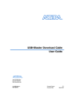
Block Diagram and Dimension
Figure 2-1: Block Diagram of the USB-Blaster Download Cable
USBVCC
VCC
USB
Receptacle
USB Interface
Chip
EPM7064AETC44
Voltage Translator
Circuitry
Pin 1
10-Pin
Female Plug
VCC (TRGT)
I/O
I/Os
I/O
I/O
I/Os
I/O
I/O
I/O
I/O
I/O
Figure 2-2: Dimension of the USB-Blaster Download Cable
0.5 (1)
7.5 (1)
2.5
1.0
(1) Applies to Rev. B and Rev. C.
2.0
All Dimensions are in inches.
© 2015 Altera Corporation. All rights reserved. ALTERA, ARRIA, CYCLONE, ENPIRION, MAX, MEGACORE, NIOS, QUARTUS and STRATIX words and logos are
trademarks of Altera Corporation and registered in the U.S. Patent and Trademark Office and in other countries. All other words and logos identified as
trademarks or service marks are the property of their respective holders as described at www.altera.com/common/legal.html. Altera warrants performance
of its semiconductor products to current specifications in accordance with Altera's standard warranty, but reserves the right to make changes to any
products and services at any time without notice. Altera assumes no responsibility or liability arising out of the application or use of any information,
product, or service described herein except as expressly agreed to in writing by Altera. Altera customers are advised to obtain the latest version of device
specifications before relying on any published information and before placing orders for products or services.
www.altera.com
101 Innovation Drive, San Jose, CA 95134
ISO
9001:2008
Registered
2-2
UG-USB81204
2015.08.20
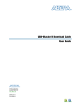
Cable-to-Board Connection
Cable-to-Board Connection
The USB-Blaster has a 10-pin female connector, which plugs into a 10-pin male header on the device
board. The male header consists of two rows of five pins, which are connected to the programming or
configuration pins of the device.
A 10-pin surface mount header can be used for the JTAG, AS, or PS download cable. However, Altera
recommends using a through-hole connector because of the repeated insertion and removal force needed.
Figure 2-3: Connectors and Dimensions
10-pin Male Header
(Device Board)
10-pin Female Connector
(USB-Blaster Download Cable)
0.425 Typ.
Top View
Side View
0.100
10
8
6
4
2
9
7
5
3
1
0.100
0.023 Sq .
0.235
0.250 Typ.
0.100 Sq.
0.025 Sq.
0.700 Typ.
Spacing between pin centers is 0.1 inches.
Dimensions are in inches
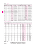
Pin Description
The following table lists the pins of the USB-Blaster female plug and describes their functions in the
JTAG, active serial and passive serial modes.
Table 2-1: Signal Names of the USB-Blaster Female Plug
Pin
AS Mode
PS Mode
JTAG Mode
Signal Name
Description
Signal Name
Description
Signal Name
Description
1
DCLK
Clock signal.
DCLK
Clock signal.
TCK
Clock signal.
2
GND
Signal ground.
GND
Signal ground.
GND
Signal ground.
3
CONF_DONE
TDO
Data from device.
4
VCC(TRGT)
VCC(TRGT)
Target power supplied
by the device board.
5
nCONFIG
6
nCE
Altera Corporation
Configuration
done.
Target power
supplied by
the device
board.
Configuration
control.
Cyclone chip
enable.
CONF_DONE
VCC(TRGT)
nCONFIG
—
Configuration
done.
Target power
supplied by
the device
board.
Configuration
control.
—
TMS
—
JTAG state machine
control.
—
Specifications for USB-Blaster Download Cable
Send Feedback
UG-USB81204
2015.08.20
AS Mode
Pin
2-3
Operating Conditions
Signal Name
7
DATAOUT
8
nCS
9
ASDI
10
GND
PS Mode
Description
Signal Name
Active serial
data out.
Description
Signal Name
Description
Configuration
status.
—
—
—
—
—
—
DATA0
Data to device.
TDI
Data to device.
GND
Signal ground.
GND
Signal ground.
nSTATUS
Serial
configuration
device chip
select.
Active serial
data in.
Signal ground.
JTAG Mode
Operating Conditions
Use the provided maximum ratings, recommended operating conditions and DC operating conditions to
ensure the correct usage of the USB-Blaster download cable.
Table 2-2: Absolute Maximum Ratings
Symbol
Parameter
Conditions
Min
Max
Unit
VCC(TRGT) Target supply voltage
With respect to ground
–0.3
5.5
V
VCC(USB)
USB supply voltage
With respect to ground
–0.5
6.0
V
Input current
TDO or dataout
–10.0
10.0
mA
–20.0
20.0
mA
–50.0
50.0
mA
Conditions
Min
Max
Unit
Target supply voltage,
5.0-V operation
—
4.75
5.25
V
Target supply voltage,
3.3-V operation
—
3.0
3.6
V
Target supply voltage,
2.5-V operation
—
2.375
2.625
mA
Target supply voltage,
1.8-V operation
—
1.71
1.89
mA
Target supply voltage,
1.5-V operation
—
1.43
1.57
mA
II
Io
Output current for Rev.
A or Rev. B cable
Output current for Rev.
C cable
TCK, TMS, TDI, nCS, nCE
Table 2-3: Recommended Operating Conditions
Symbol
VCC(TRGT)
Parameter
Specifications for USB-Blaster Download Cable
Send Feedback
Altera Corporation
2-4
UG-USB81204
2015.08.20
Operating Conditions
Table 2-4: DC Operating Conditions for USB-Blaster Rev. A and B
Symbol
Parameter
Conditions
Min
Max
Unit
VIH
High-level input
voltage
—
VCC(TRGT) – 0.2
—
V
VIL
Low-level input
voltage
—
—
0.15
V
5.0-V high-level
output voltage
VCC(TRGT) = 4.5 V, IOH = 1 mA
4.4
—
V
3.3-V high-level
output voltage
VCC(TRGT) = 3.0 V, IOH = 1 mA
2.9
—
V
2.5-V high-level
output voltage
VCC(TRGT) = 2.375 V, IOH = 1
mA
2.275
—
V
1.8-V high-level
output voltage
VCC(TRGT) = 1.71 V, IOH = 1 mA
1.61
—
V
1.5-V high-level
output voltage
VCC(TRGT) = 1.43 V, IOH = 1 mA
1.33
—
V
5.0-V low-level
output voltage
VCC(TRGT) = 5.5 V, IOL = 1 mA
—
0.125
V
3.3-V low-level
output voltage
VCC(TRGT) = 3.6 V, IOL = 1 mA
—
0.125
V
2.5-V low-level
output voltage
VCC(TRGT) = 2.625 V, IOL = 1
mA
—
0.125
V
1.8-V low-level
output voltage
VCC(TRGT) = 1.89 V, IOL = 1 mA
—
0.125
V
1.5-V low-level
output voltage
VCC(TRGT) = 1.57 V, IOL = 1 mA
—
0.125
V
Typical ICC(TRGT) = 16 uA
—
100
uA
Min
Max
Unit
2.0
—
V
VCC(TRGT)
—
V
VCC(TRGT) >= 2.0 V
—
0.8
V
VCC(TRGT) < 2.0 V
—
0
V
VOH
VOL
ICC(TRGT) Operating
current (No
Load)
Table 2-5: DC Operating Conditions for USB-Blaster Rev. C
Symbol
Parameter
Conditions
VIH
High-level input VCC(TRGT) >= 2.0 V
voltage
VCC(TRGT) < 2.0 V
VIL
Low-level input
voltage
Altera Corporation
Specifications for USB-Blaster Download Cable
Send Feedback
UG-USB81204
2015.08.20
Power Requirements
Symbol
VOH
VOL
Parameter
Conditions
2-5
Min
Max
Unit
5.0-V high-level
output voltage
VCC(TRGT) = 4.5 V, IOH = -10
mA
3.8
—
V
3.3-V high-level
output voltage
VCC(TRGT) = 3.0 V, IOH = -8 mA
2.3
—
V
2.5-V high-level
output voltage
VCC(TRGT) = 2.375 V, IOH = -6
mA
1.8
—
V
1.8-V high-level
output voltage
VCC(TRGT) = 1.71 V, IOH = -4
mA
1.2
—
V
5.0-V high-level
output voltage
VCC(TRGT) = 5.5 V, IOL = 10 mA
—
0.8
3.3-V high-level
output voltage
VCC(TRGT) = 3.6 V, IOL = 8 mA
—
0.7
2.5-V high-level
output voltage
VCC(TRGT) = 2.625 V, IOL = 6
mA
—
0.6
1.8-V high-level
output voltage
VCC(TRGT) = 1.89 V, IOL = 4 mA
—
0.5
Typical ICC(TRGT) = 16 uA
—
100
ICC(TRGT) Operating
current (No
Load)
uA
Power Requirements
The USB-Blaster VCC(TRGT) pin must be connected to a specific voltage for the device being programmed.
Connect pull-up resistors to the same power supply as the USB-Blaster VCC(TRGT).
Table 2-6: VCC(TRGT) Power Requirements
Device Family
Voltage Required
Stratix V, Stratix IV, and Stratix III
As specified by VCCPGM or VCCPD.
Stratix II, Stratix II GX, and Stratix
GX
As specified by VCCSEL.
Arria 10
As specified by VCCPGM or VCCIO.
Arria V
As specified by VCCPD.
Arria II GX
As specified by VCCPD or VCCIO of Bank 8C
Arria GX
As specified by VCCSEL.
Cyclone V
As specified by VCCPGM or VCCPD.
Cyclone IV
As specified by VCCA or VCCIO.
Cyclone III
As specified by VCCA or VCCIO.
Max 10
As specified by VCCIO.
FPGAs
Specifications for USB-Blaster Download Cable
Send Feedback
Altera Corporation
2-6
UG-USB81204
2015.08.20
RoHS Compliance
Device Family
Voltage Required
Configuration Devices
EPCS
3.3 V
EPCQ
3.3 V
EPCQ-L
1.8 V
RoHS Compliance
Table 2-7: Hazardous Substances and Concentration
A value of 0 indicates that the concentration of the hazardous substance in all homogeneous materials in the parts
is below the relevant threshold as specified by the SJ/T11363-2006 standard.
Part Name
Lead (Pb)
Cadmium
(Cd)
Hexavalent
Chromium
(Cr6+)
Mercury
(Hg)
Polybromi‐
nated
Biphenyls
(PBB)
Polybrominated
Diphenyl Ethers
(PBB)
Electronic
components
0
0
0
0
0
0
Populated
circuit board
0
0
0
0
0
0
Manufacturing
process
0
0
0
0
0
0
Packing
0
0
0
0
0
0
Altera Corporation
Specifications for USB-Blaster Download Cable
Send Feedback
Using the USB-Blaster Download Cable
3
2015.08.20
UG-USB81204
Subscribe
Send Feedback
To start using the USB-Blaster download cable, you must install the drivers on your system and set up the
hardware in the Quartus II software. Altera recommends that you use the latest version of the Quartus II
software.
To program or configure the device, connect the host system to the device board using the USB-Blaster
download cable and initiate the programming or configuration using the Quartus II Programmer. You
can also use the cable with the Quartus II SignalTap® II Logic Analyzer for logic analysis.
Installing the USB-Blaster Driver on Windows
1. Locate the USB-Blaster driver in \<Quartus II system directory>\drivers\usb-blaster.
If the driver is not in your directory, download the driver from www.altera.com/support/software/drivers.
2. Connect the USB-Blaster download cable to your PC.
3. Open Device Manager. In the Other devices tab, select and right click USB-Blaster. Then, click
Update Driver Software.
4. Click Browse. Browse to \<Quartus II system directory>\drivers\usb-blaster and click Next.
The Windows security warning is displayed.
5. Click Install to begin installing the driver.
6. Click Finish when the driver is installed.
7. Restart your system.
Related Information
https://www.altera.com/support/support-resources/download/drivers/dri-index.html
Installing the USB-Blaster Driver on Linux
The Quartus II software uses the USB drivers (usbfs) provided by Red Hat Linux to access the USBBlaster download cable. You need system administration (root) privileges to configure the drivers. You
must also change the permission on the ports before using the USB-Blaster download cable to program
devices.
Related Information
https://www.altera.com/support/support-resources/download/drivers/dri-index.html
© 2015 Altera Corporation. All rights reserved. ALTERA, ARRIA, CYCLONE, ENPIRION, MAX, MEGACORE, NIOS, QUARTUS and STRATIX words and logos are
trademarks of Altera Corporation and registered in the U.S. Patent and Trademark Office and in other countries. All other words and logos identified as
trademarks or service marks are the property of their respective holders as described at www.altera.com/common/legal.html. Altera warrants performance
of its semiconductor products to current specifications in accordance with Altera's standard warranty, but reserves the right to make changes to any
products and services at any time without notice. Altera assumes no responsibility or liability arising out of the application or use of any information,
product, or service described herein except as expressly agreed to in writing by Altera. Altera customers are advised to obtain the latest version of device
specifications before relying on any published information and before placing orders for products or services.
www.altera.com
101 Innovation Drive, San Jose, CA 95134
ISO
9001:2008
Registered
3-2
UG-USB81204
2015.08.20
Installing on Red Hat Enterprise 4 or Earlier Versions
Installing on Red Hat Enterprise 4 or Earlier Versions
1. Add the following lines to the /etc/hotplug/usb.usermap file.
#
# Altera USB-Blaster
#
usbblaster 0x03 0x09fb 0x6001 0x0 0x0 0x0 0x0 0x0 0x0 0x0 0x0 0x0
usbblaster 0x03 0x09fb 0x6002 0x0 0x0 0x0 0x0 0x0 0x0 0x0 0x0 0x0
usbblaster 0x03 0x09fb 0x6003 0x0 0x0 0x0 0x0 0x0 0x0 0x0 0x0 0x0
2. Create a file named /etc/hotplug/usb/usbblaster and add the following lines to it.
#!/bin/sh
# USB-Blaster hotplug script
# Allow any user to access the cable
chmod 666 $DEVICE
3. Make the file executable.
4. Complete your installation by setting up the programming hardware in the Quartus II software as
described in the following section.
Installing on Red Hat Enterprise 5
1. Create a file named /etc/udev/rules.d/51-usbblaster.rules and add the following lines to it. Ensure that all
code after #USB-Blaster must be in one line.
# USB-Blaster
BUS=="usb", SYSFS{idVendor}=="09fb", SYSFS{idProduct}=="6001", MODE="0666",
PROGRAM="/bin/sh -c 'K=%k; K=$${K#usbdev}; printf /proc/bus/usb/%%03i/%%03i $${K%%%
%.*} $${K#*.}'", RUN+="/bin/chmod 0666 %c"
2. Complete your installation by setting up the programming hardware in the Quartus II software.
Setting up the USB-Blaster Hardware in the Quartus II Software
1. Launch the Quartus II software.
2. Click Tools > Programmer.
3. Click Hardware Setup.
Altera Corporation
Using the USB-Blaster Download Cable
Send Feedback
UG-USB81204
2015.08.20
Connecting the USB-Blaster Download Cable to the Board
3-3
Figure 3-1: Hardware Setup Dialog Box
The Hardware Settings tab of the Hardware Setup dialog box is displayed.
4. From the Currently selected hardware drop-down list, select USB-Blaster [USB-0].
5. Click Close to close the Hardware Setup dialog box.
6. In the Programmer window, select the desired programming mode from the Mode drop-down list.
Table 3-1: Programming Modes
Mode
Joint Test Action Group (JTAG)
In-Socket Programming
Passive Serial
Active Serial Programming
Description
Programs or configures all supported Altera devices except EPCS,
EPCQ, and EPCQ-L devices.
USB-Blaster does not support this programming mode.
Configures all supported Altera devices except EPCS, EPCQ, and
EPCQ-L devices.
Programs a single EPCS, EPCQ, or EPCQ-L device.
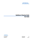
Connecting the USB-Blaster Download Cable to the Board
1. Disconnect the power cable from the device board.
2. Connect the USB-Blaster download cable to your PC.
3. Plug the USB-Blaster download cable into the 10-pin header on the device board.
Using the USB-Blaster Download Cable
Send Feedback
Altera Corporation
3-4
Connecting the USB-Blaster Download Cable to the Board
UG-USB81204
2015.08.20
Figure 3-2: Connection to the Device Board
BLA
ST
SID ER
E
PIN1
TAR
GET
SIDE
10-pin Female Connector
(connects to target printed
circuit board 10-pin male
header)
4. Connect the power cable to the device board.
The Found New Hardware wizard may open and prompt you to install a new hardware driver. Close
the wizard and follow the steps provided in subsequent sections to install the hardware driver.
5. To disconnect the USB Blaster download cable from the device board, follow these steps to ensure that
the cable is not damaged.
a. Remove power from the device board.
b. Unplug the USB-Blaster download cable from the board.
c. Unplug the USB-Blaster download cable from your PC.
Altera Corporation
Using the USB-Blaster Download Cable
Send Feedback
4
Revision History for USB-Blaster Download
Cable User Guide
2015.08.20
UG-USB81204
Send Feedback
Subscribe
Date
Version
Changes
August 2015
2015.08.20
• Removed PROC_RST signal which is not supported
in USB-Blaster.
May 2015
2015.05.04
• Updated the document organization.
• Added new devices in the following sections:
Supported Devices and Host Systems and Power
Requirements.
• Updated the procedure on driver installation for
Windows.
• Revised the pin width of the female plug.
April 2009
2.5
• Updated “Supported Devices” section.
• Updated “Software Requirements”.
• Deleted handnote in “Installing the USB-Blaster
Driver on Windows Vista Systems”.
• Updated Table 2–1.
• Added a handnote in “Circuit Board Header
Connection”.
• Updated Table 2–5.
April 2008
2.4
• Added “Statement of China-RoHS Compliance”.
• Added Table 2–8.
• Added “Installing the USB-Blaster Driver on
Windows Vista Systems”.
© 2015 Altera Corporation. All rights reserved. ALTERA, ARRIA, CYCLONE, ENPIRION, MAX, MEGACORE, NIOS, QUARTUS and STRATIX words and logos are
trademarks of Altera Corporation and registered in the U.S. Patent and Trademark Office and in other countries. All other words and logos identified as
trademarks or service marks are the property of their respective holders as described at www.altera.com/common/legal.html. Altera warrants performance
of its semiconductor products to current specifications in accordance with Altera's standard warranty, but reserves the right to make changes to any
products and services at any time without notice. Altera assumes no responsibility or liability arising out of the application or use of any information,
product, or service described herein except as expressly agreed to in writing by Altera. Altera customers are advised to obtain the latest version of device
specifications before relying on any published information and before placing orders for products or services.
www.altera.com
101 Innovation Drive, San Jose, CA 95134
ISO
9001:2008
Registered
4-2
UG-USB81204
2015.08.20
Revision History for USB-Blaster Download Cable User Guide
Date
Version
Changes
May 2007
2.3
• Updated “Introduction”.
• Added warning note about USB-Blaster cable in
“Hardware Setup” section.
• Added information on Linux setup in “Installing
the USB-Blaster Driver on Linux” section.
• Added feetpara note on driver information just
before the “Setting Up the USB-Blaster Hardware
in the Quartus II Software” section.
• Updated USB-Blaster installation procedure for QII
6.1 (32-bit or 64-bit) in “Installing the USB-Blaster
Driver on Windows 2000 and Windows XP
Systems” section.
March 2007
2.2
• Update to “Installing the USB-Blaster Driver on
Windows 2000 and Windows XP Systems” section.
July 2006
2.1
Minor update to Chapter 2, USB-Blaster Specifica‐
tions.
June 2006
2.0
• Updated Figure 2–1, Table 2–1, and Table 2–7.
• Added Table 2–6.
December
2004
1.2
Update to conditions in Table 2–2.
November
2004
1.1
Minor update.
July 2004
1.0
Initial release.
Altera Corporation
Revision History for USB-Blaster Download Cable User Guide
Send Feedback