1
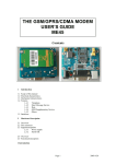
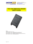
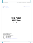
THE GSM/GPRS/CDMA MODEM
USER’S GUIDE
ME1203
Contents
1
Introduction
1.1
1.2
1.3
1.4
Scope of this manual
Electrical characteristics
Mechanical characteristics
Features
1.4.1
Telephony
1.4.2
Short Message Service
1.4.3
Data
1.4.4
GSM Supplementary Service
1.4.5
Others
1.5 Interfaces
2
Hardware Description
2.1 Overview
2.2 The connector
Page 1
2003-8-28
2.3 Signal descriptions
2.3.1
Power supply
2.3.2
Serial link
2.4 Overview
2.5 Functional description
1 Introduction
The ME1203 is designed to provide a quick and easy solution to systems that need to access
GSM/GPRS/CDMA network/functionality. The modem is full type approved and ready to use. It
employs the proven GSM WISMO™ technology from WAVECOM.
1.1 Scope of this manual
This document describes the hardware interface and the technical specification of the ME1203. For
information about controlling the modem via the AT commands, refer to the ‘ AT command manual’.
1.2 Electrical characteristics
•
•
•
•
•
•
•
•
•
•
•
Dual band GSM modem E-GSM 900/1800 or E-GSM 900/1900
Class 4: 2W for GSM 900
Class 1: 1W for GSM 1800/1900
Voice, SMS, Fax and data
Tricodec: Full Rate, Enhanced Full Rate and Half Rate
3V SIM interface
Power supply: 5V @ 2A
300mA average current consumption
9mA in idle mode
Operating temperature: -20°C to + 50°C
Storage temperature: -35°C to +85°C
1.3 Mechanical characteristics
•
•
Small size: 75mm(L) x 43mm(W) x 12mm(H)
Mounting: 2 screw holes
1.4 Features
1.4.1
•
•
•
Telephony (TCH/FS) and Emergency calls
Full Rate, Enhanced Full Rate and Half Rate
DTMF functions
1.4.2
•
•
Short Message Service
Point to Point MT and MO
SMS Cell Broadcast
1.4.3
•
•
•
•
Telephony
Data
Data circuit asynchronous, transparent and non-transparent up to 14.4kbps
Automatic fax group 3 (Class 1 and 2)
Alternate speech and fax
MNP2, V.42bis
Page 2
2003-8-28
GPRS packet data features
•
•
•
GPRS class 2 / Class B
Coding schemes CS1 to CS4
Compliant with SMG31bis
1.4.4
•
•
•
•
•
•
•
•
•
Call Forwarding
Call Barring
Multi Party
Call Waiting and Call Hold
Calling Line Identity
Advice of Charge
USSD
Closed User Group
Explicit Call Transfer
1.4.5
•
•
•
•
•
•
•
•
GSM Supplementary Service
Others
ME + SIM phone book management
Fixed Dialling Number
SIM Toolkit Class 2
SIM, network and service provider locks
Real Time Clock
Alarm management
Software upgrade through Xmodem protocol
UCS2 character set management
1.5 Interfaces
•
•
•
Single Antenna Interface
3V only internal SIM interface
RS232 Interface
2
Hardware Description
2.1 Overview
The ME1203 includes a Wavecom Wismo2C2/2D module, a SIM card holder , a IDC10-pin header
and a RF connector.
Mounting holes
LED
RS232
SIM
DCIN
5~12DC
Mounting holes
Mounting holes
Antenna
SMA
Figure : Top view
Page 3
2003-8-28
2.2 The connector
Signal description
2.2.1
Power supply:
Power supply design is an important factor. The GSM modem transmits in burst sequences, therefore
the power supply must be able to deliver high current peaks in short period of time.
Supply voltage = 5V ~12VDC
Supply current = 2 amperes.
2.2.2
3
Serial link
The Optional RS232 Interface
3.1 Overview:
The development board is designed for system integrators to explore the modem’s functionality. It
consists of a power supply, V.28 serial port, buzzer, connector for microphone + earpiece, general I/O
DIP switches, connector for 5x5 keypad, Reset button, Boot button and ON/OFF button.
3.2 Functional description
3.2.1
The serial port connector
2
4
6
8
10
1
3
5
7
9
Figure : The IDC 10-pin header of V.28 serial port
1
2
3
4
5
Type
DCD
RXD
TXD
DTR
GND
Description
RS232 interface, output
RS232 interface, output
RS232 interface, input
RS232 interface, input
GND
6
7
8
9
10
Page 4
Type
DSR
RTS
CTS
RI
NC
Description
RS232 interface, output
RS232 interface, input
RS232 interface, output
RS232 interface, output
2003-8-28