1
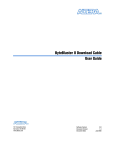
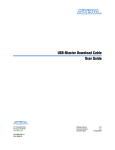
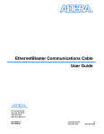
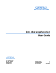
MasterBlaster Serial/USB
Communications Cable User Guide
101 Innovation Drive
San Jose, CA 95134
www.altera.com
Software Version:
Document Version:
Document Date:
80
1.1
© July 2008
Copyright © 2008 Altera Corporation. All rights reserved. Altera, The Programmable Solutions Company, the stylized Altera logo, specific device designations, and all other
words and logos that are identified as trademarks and/or service marks are, unless noted otherwise, the trademarks and service marks of Altera Corporation in the U.S. and other
countries. All other product or service names are the property of their respective holders. Altera products are protected under numerous U.S. and foreign patents and pending applications, maskwork rights, and copyrights. Altera warrants performance of its semiconductor products to current specifications in accordance with Altera's standard warranty,
but reserves the right to make changes to any products and services at any time without notice. Altera assumes no responsibility or liability arising out of the application or use of
any information, product, or service described herein except as expressly agreed to in writing by Altera Corporation. Altera customers are advised to obtain the latest version of
device specifications before relying on any published information and before placing orders for products or services.
UG-MB81204-1.1
P25-10322-00
Contents
Chapter 1. Installing the MasterBlaster Serial/USB Communications Cable
Introduction . . . . . . . . . . . . . . . . . . . . . . . . . . . . . . . . . . . . . . . . . . . . . . . . . . . . . . . . . . . . . . . . . . . . . . . . . . . . 1–1
Installation . . . . . . . . . . . . . . . . . . . . . . . . . . . . . . . . . . . . . . . . . . . . . . . . . . . . . . . . . . . . . . . . . . . . . . . . . . . . . 1–1
Installation on a Windows PC . . . . . . . . . . . . . . . . . . . . . . . . . . . . . . . . . . . . . . . . . . . . . . . . . . . . . . . . . . 1–2
Installation on a Linux or UNIX Workstation . . . . . . . . . . . . . . . . . . . . . . . . . . . . . . . . . . . . . . . . . . . . . 1–3
Selecting the MasterBlaster Cable for the SignalTap II Logic Analyzer . . . . . . . . . . . . . . . . . . . . . . . . 1–4
Chapter 2. MasterBlaster Serial/USB Communications Cable Data Sheet
Features . . . . . . . . . . . . . . . . . . . . . . . . . . . . . . . . . . . . . . . . . . . . . . . . . . . . . . . . . . . . . . . . . . . . . . . . . . . . . . . . 2–1
Functional Description . . . . . . . . . . . . . . . . . . . . . . . . . . . . . . . . . . . . . . . . . . . . . . . . . . . . . . . . . . . . . . . . . . . 2–1
Download Modes . . . . . . . . . . . . . . . . . . . . . . . . . . . . . . . . . . . . . . . . . . . . . . . . . . . . . . . . . . . . . . . . . . . . . 2–2
SignalTap II Logic Analysis . . . . . . . . . . . . . . . . . . . . . . . . . . . . . . . . . . . . . . . . . . . . . . . . . . . . . . . . . . . . 2–2
MasterBlaster Connections . . . . . . . . . . . . . . . . . . . . . . . . . . . . . . . . . . . . . . . . . . . . . . . . . . . . . . . . . . . . . 2–3
Header & Plug Connections . . . . . . . . . . . . . . . . . . . . . . . . . . . . . . . . . . . . . . . . . . . . . . . . . . . . . . . . . . 2–3
Powering the MasterBlaster Cable . . . . . . . . . . . . . . . . . . . . . . . . . . . . . . . . . . . . . . . . . . . . . . . . . . . . 2–4
Circuit Board Header Connection . . . . . . . . . . . . . . . . . . . . . . . . . . . . . . . . . . . . . . . . . . . . . . . . . . . . . 2–5
LED Status . . . . . . . . . . . . . . . . . . . . . . . . . . . . . . . . . . . . . . . . . . . . . . . . . . . . . . . . . . . . . . . . . . . . . . . . . . . 2–5
Operating Conditions . . . . . . . . . . . . . . . . . . . . . . . . . . . . . . . . . . . . . . . . . . . . . . . . . . . . . . . . . . . . . . . . . . . . 2–5
References . . . . . . . . . . . . . . . . . . . . . . . . . . . . . . . . . . . . . . . . . . . . . . . . . . . . . . . . . . . . . . . . . . . . . . . . . . . . . . 2–7
Chapter Info. Additional Information
Referenced Documents . . . . . . . . . . . . . . . . . . . . . . . . . . . . . . . . . . . . . . . . . . . . . . . . . . . . . . . . . . . . . . . .
Revision History . . . . . . . . . . . . . . . . . . . . . . . . . . . . . . . . . . . . . . . . . . . . . . . . . . . . . . . . . . . . . . . . . . . . .
How to Contact Altera . . . . . . . . . . . . . . . . . . . . . . . . . . . . . . . . . . . . . . . . . . . . . . . . . . . . . . . . . . . . . . . .
Typographic Conventions . . . . . . . . . . . . . . . . . . . . . . . . . . . . . . . . . . . . . . . . . . . . . . . . . . . . . . . . . . . . .
© July 2008
Altera Corporation
Info–1
Info–1
Info–1
Info–2
MasterBlaster Serial/USB Communications Cable User Guide
iv
MasterBlaster Serial/USB Communications Cable User Guide
© July 2008 Altera Corporation
List of Figures
v
List of Figures
Figure 1–1: MasterBlaster Serial/USB Communications Cable . . . . . . . . . . . . . . . . . . . . . . . . . . . . . . . . . . .
Figure 1–2: The Hardware Setup Dialog Box . . . . . . . . . . . . . . . . . . . . . . . . . . . . . . . . . . . . . . . . . . . . . . . . . . .
Figure 2–1: MasterBlaster Serial/USB Communications Cable . . . . . . . . . . . . . . . . . . . . . . . . . . . . . . . . . . .
Figure 2–2: MasterBlaster 10-Pin Female Plug Dimensions . . . . . . . . . . . . . . . . . . . . . . . . . . . . . . . . . . . . . .
Figure 2–1: 10-Pin Male Header Dimensions . . . . . . . . . . . . . . . . . . . . . . . . . . . . . . . . . . . . . . . . . . . . . . . . . . .
© July 2008
Altera Corporation
1-2
1-3
2-2
2-4
2-5
MasterBlaster Serial/USB Communications Cable User Guide
vi
MasterBlaster Serial/USB Communications Cable User Guide
List of Figures
© July 2008 Altera Corporation
List of Tables
vii
List of Tables
Table 2–1: MasterBlaster 9-Pin Serial D-Type Connector Pin-Outs . . . . . . . . . . . . . . . . . . . . . . . . . . . . . . . .
Table 2–2: MasterBlaster Female Plug’s Pin Names & Download Modes . . . . . . . . . . . . . . . . . . . . . . . . . . .
Table 2–1: LED Status Indicator . . . . . . . . . . . . . . . . . . . . . . . . . . . . . . . . . . . . . . . . . . . . . . . . . . . . . . . . . . . . . .
Table 2–2: MasterBlaster Cable Absolute Maximum Ratings . . . . . . . . . . . . . . . . . . . . . . . . . . . . . . . . . . . . .
Table 2–3: MasterBlaster Cable Recommended Operating Conditions . . . . . . . . . . . . . . . . . . . . . . . . . . . . .
Table 2–4: MasterBlaster Cable DC Operating Conditions . . . . . . . . . . . . . . . . . . . . . . . . . . . . . . . . . . . . . . .
© July 2008
Altera Corporation
2-3
2-4
2-5
2-6
2-6
2-6
MasterBlaster Serial/USB Communications Cable User Guide
viii
MasterBlaster Serial/USB Communications Cable User Guide
List of Tables
© July 2008 Altera Corporation
1. Installing the MasterBlaster
Serial/USB Communications Cable
Introduction
The MasterBlasterTM serial/USB communications cable is a download cable that
allows PC and workstation users to program and configure devices in-system. The
MasterBlaster cable provides multi-device JTAG chain configuration and
programming support for SRAM-based devices, such as APEXTM 20K and MercuryTM
devices, EEPROM-based devices, such as MAX® 3000 and MAX 7000 devices, and
configuration devices, such as the EPC2 and EPC16. You can also use the
MasterBlaster cable to run SignalTap® II logic analysis. The MasterBlaster cable also
provides multi-device passive serial (PS) chain configuration support for
SRAM-based devices, such as APEX 20K and Mercury devices. This cable can be used
in 2.5-, 3.3-, and 5.0-V systems.
Altera® offers a variety of hardware to program and configure Altera devices. For
conventional device programming, in-system programming, and in-circuit
reconfiguration, designers can choose from a wide range of programming hardware
options.
This user guide provides the following information about the MasterBlaster™
serial/USB communications cable.
■
How to install the cable and its driver software
■
How to use the cable after installation
■
A complete list of the cable’s features
■
A functional description of the cable
Installation
The MasterBlaster communications cable connects a circuit board to the USB
(Windows 2000, Windows XP x32 edition, and Windows Vista x32 edition only) or RS232 serial port (called a COM port on a PC) on a PC, UNIX, or Linux workstation. The
10-pin female plug for the cable connects to a 10-pin male header on the circuit board
that contains the target device(s), as shown in Figure 1–1. Programming or
configuration data can be downloaded from the serial or USB port, using the Quartus®
II Programmer, through the MasterBlaster cable to the circuit board through these
connections.
1
The Quartus II software version 8.1 and later will no longer support MasterBlaster
communication cable.
The MasterBlaster communications cable receives power from any one of the
following sources:
© July 2008
■
5.0- or 3.3-V circuit boards
■
5.0 V from the USB cable (Windows 2000, Windows XP x32 edition, and Windows
Vista x32 edition only)
Altera Corporation
MasterBlaster Serial/USB Communications Cable User Guide
1–2
Cable
Chapter 1: Installing the MasterBlaster Serial/USB Communications
■
DC power supply, which is supplied with the MasterBlaster communications cable
The MasterBlaster cable connects to a computer through a serial or USB port, and
connects to the circuit board through a standard 10-pin female connector.
Installation on a Windows PC
To install and set up the MasterBlaster cable for device configuration or programming
on a Windows PC, follow these steps:
1. Connect one end of a standard RS-232 cable or a standard USB cable, to the
MasterBlaster cable and connect the other end to the appropriate port on the
computer.
1
If you are using the MasterBlaster communications cable with the USB port, the
Windows 2000, Windows XP, or Windows Vista operating system prompts you to
locate the MasterBlaster USB driver mblaster.inf file. The MasterBlaster driver is
located in your \<Quartus II system directory>\drivers directory.
2. Connect the 16-pin female header end of the cable to the 16-pin male MasterBlaster
port, and the 10-pin female end of the cable to the
10-pin male header on the target printed circuit board. Figure 1–1 shows the
MasterBlaster serial/USB communications cable.
Figure 1–1. MasterBlaster Serial/USB Communications Cable
3. Open the Quartus II Programmer. Choose Programmer (Tools menu) or choose
New (File menu). Click the Other Files tab, select Chain Description File, and
click OK.
4. In the Programmer window, click Hardware Setup. The Hardware Settings tab of
the Hardware Setup dialog box is displayed.
5. Click Add Hardware. The Add Hardware dialog box is displayed.
6. In the Hardware type list, select either MasterBlaster (COM) or MasterBlaster
(USB).
MasterBlaster Serial/USB Communications Cable User Guide
© July 2008 Altera Corporation
Chapter 1: Installing the MasterBlaster Serial/USB Communications Cable
Installation
1–3
1
The USB option is available only for Windows 2000, Windows XP x32 edition and
Windows Vista x32 edition systems.
1
The COM option is available only for Windows 2000, Windows XP x32 edition,
Windows XP x64 edition and Windows Vista x32 edition systems.
7. In the Port list, select the appropriate port.
8. If you are using a serial port, in the Baud rate list, select a baud rate appropriate
for your computer.
9. Click OK to close the Add Hardware dialog box. You will see MasterBlaster in the
Available hardware items section of the Hardware Setup dialog box.
10. Click on MasterBlaster to highlight it, then click on the Select Hardware button to
the right of the Available hardware items section. You will now see MasterBlaster
and your selected port in the Currently selected hardware section of the window,
as shown in Figure 1–2.
11. Click Close to close the Hardware Setup dialog box.
Figure 1–2. The Hardware Setup Dialog Box
12. Close the Programmer window.
Installation on a Linux or UNIX Workstation
To install and set up the MasterBlaster cable for device configuration or programming
on a Linux or UNIX Workstation, follow these steps:
1. With a standard RS-232 cable, connect one end of the cable to the MasterBlaster
cable, and connect the other end of the cable to the appropriate port on the
computer.
2. Connect the 16-pin female header end of the cable to the 16-pin male MasterBlaster
port, and the 10-pin female end of the cable to the 10-pin male header on the target
printed circuit board, as shown in Figure 1–1.
© July 2008
Altera Corporation
MasterBlaster Serial/USB Communications Cable User Guide
1–4
Cable
Chapter 1: Installing the MasterBlaster Serial/USB Communications
3. Open the Quartus II Programmer. Choose Programmer (Tools menu) or choose
New (File menu). Click the Other Files tab, select Chain Description File, and
click OK.
4. In the Programmer window, click Hardware Setup. The Hardware Settings tab of
the Hardware Setup dialog box is displayed.
5. Click Add Hardware. The Add Hardware dialog box is displayed.
6. In the Hardware type list, select MasterBlaster.
7. In the Port box, select the name of the appropriate serial port. Also, make sure you
have read and write permission for the serial port.
8. In the Baud rate list, select a baud rate that is appropriate for your computer.
9. Click OK.
10. In the Hardware Setup dialog box, click Close.
Selecting the MasterBlaster Cable for the SignalTap II Logic Analyzer
To select the MasterBlaster communications cable for the SignalTap II Logic Analyzer,
follow these steps.
1. Choose SignalTap II Logic Analyzer (Tools menu). The SignalTap window will
open.
2. Under JTAG Chain Configuration, select MasterBlaster in the Hardware
pull-down list.
If the MasterBlaster cable does not appear in the Hardware list, continue as follows:
1. Under JTAG Chain Configuration, click Setup.
2. Click Add Hardware in the Hardware Setup dialog box to add a hardware setup
for the MasterBlaster cable.
3. Click Add Hardware in the Hardware Setup dialog box to add a hardware setup
for the communications cable.
f
For more information about SignalTap II logic analysis with the MasterBlaster cable,
refer to Selecting the Communications Cable for the SignalTap II Logic Analyzer in the
Quartus II Help.
MasterBlaster Serial/USB Communications Cable User Guide
© July 2008 Altera Corporation
2. MasterBlaster Serial/USB
Communications Cable Data Sheet
Features
■
Supports SignalTap® II logic analysis in the Altera® Quartus® II software
■
Allows PC, Linux, and UNIX users to perform the following functions:
■
Configure Stratix® IV, Stratix III, Stratix II, Stratix II GX, Stratix, Stratix GX,
CycloneTM III, Cyclone II, Cyclone, MercuryTM, APEXTM II, APEX 20K, FLEX®
10K, FLEX 3000A, FLEX 6000, FLEX 8000 devices, and ExcaliburTM embedded
processor solutions
■
Program MAX® II, MAX 9000, MAX 7000S, MAX 7000B, MAX 7000A, EPC2,
EPC4, EPC8, and EPC16 devices in-system
■
Supports operation with VCC at 5.0 V, 3.3 V, or 2.5 V
■
Provides a fast, low-cost method for in-system programming
■
Downloads data from the Quartus II development software and the MAX+PLUS®
II software versions 9.3 and higher
■
Interfaces with an RS-232 serial or universal serial bus (USB) port
■
Uses a 10-pin circuit board connector
Functional Description
The MasterBlasterTM serial/USB communications cable (ordering code:
PL-MASTERBLASTER) is a standard PC serial or USB port hardware interface (see
Figure 2–1). This cable downloads configuration data to Stratix IV, Stratix III, Stratix
II, Stratix II GX, Stratix, Stratix GX, Cyclone III, Cyclone II, Cyclone, Mercury,
APEX II, APEX 20K (including APEX 20K, APEX 20KE, and APEX 20KC), FLEX 10K
(including FLEX 10KA and FLEX 10KE), FLEX 8000, and FLEX 6000 devices, as well
as programming data to MAX II, MAX 9000, MAX 7000S, and MAX 7000A (including
MAX 7000AE) devices. Because design changes are downloaded directly to the
device, prototyping is easy and multiple design iterations can be accomplished in
quick succession. The MasterBlaster cable also supports in-circuit debugging with the
SignalTap II embedded logic analyzer in Stratix, APEX II, and APEX 20K devices.
© July 2008
Altera Corporation
MasterBlaster Serial/USB Communications Cable User Guide
2–2
Chapter 2: MasterBlaster Serial/USB Communications Cable Data Sheet
Functional Description
Figure 2–1. MasterBlaster Serial/USB Communications Cable
Download Modes
The MasterBlaster cable provides two download modes:
■
Passive serial mode (PS)—In this mode the Quartus II Programmer can configure
all Altera devices supported by the Quartus II software except MAX 3000 and
MAX 7000 devices.
■
JTAG mode—Industry-standard IEEE Std. 1149.1 Joint Test Action Group (JTAG)
interface for programming JTAG-capable devices. In JTAG mode, the Quartus II
Programmer can program or configure all Altera devices supported by the
Quartus II software, except FLEX 6000 devices. FLEX 6000 devices can be in a
JTAG chain, but they must be bypassed; they cannot be configured. The Quartus II
Programmer can also program EPC2, EPC4, EPC8, and EPC16 configuration
devices in this mode. The JTAG chain can contain any number and combination of
Altera and non-Altera devices that comply with this IEEE 1149.1 specification.
SignalTap II Logic Analysis
The SignalTap II logic analysis enables captured device data at specified trigger points
and stores the data in APEX II and APEX 20K embedded system blocks (ESBs). This
data is then sent to the JTAG IEEE Std. 1149.1 port of an APEX II or APEX 20K device,
uploaded through the MasterBlaster communications cable, and displayed in the
Quartus II Waveform Editor.
f
For more information on SignalTap logic analysis, see the Design Debugging using the
SignalTap II Embedded Logic Analyzer chapter in volume 3 of the Quartus II Handbook.
MasterBlaster Serial/USB Communications Cable User Guide
© July 2008 Altera Corporation
Chapter 2: MasterBlaster Serial/USB Communications Cable Data Sheet
Functional Description
2–3
MasterBlaster Connections
The MasterBlaster cable connects to a computer through a serial or USB port and
connects to the circuit board through a standard 10-pin female connector. Data is
downloaded from the serial or USB port through the MasterBlaster cable to the circuit
board through the connections discussed in this section.
Header & Plug Connections
The 9-pin male D-type connector connects to an RS-232 port with a standard serial
cable. See Table 2–1.
1
The USB connector can be used with any standard USB cable.
Table 2–1. MasterBlaster 9-Pin Serial D-Type Connector Pin-Outs
f
Pin
Signal Name
Description
2
rx
Receive data
3
tx
Transmit data
4
dtr
Data terminal ready
5
GND
Signal ground
6
dsr
Data set ready
7
rts
Request to send
8
cts
Clear to send
For more information on 9-pin versus 25-pin serial connectors, search for “9-pin or 25pin serial connectors” in the Altera solutions database at www.altera.com.
The 10-pin female plug connects to a 10-pin male header on the circuit board
containing the target device(s). Figure 2–2 shows the dimensions of the female plug.
© July 2008
Altera Corporation
MasterBlaster Serial/USB Communications Cable User Guide
2–4
Chapter 2: MasterBlaster Serial/USB Communications Cable Data Sheet
Functional Description
Figure 2–2. MasterBlaster 10-Pin Female Plug Dimensions
0.425 Typ.
Color Strip
1
3
5
7
9
2
4
6
8
10
0.250 Typ.
0.100 Sq.
0.025 Sq.
0.700 Typ.
Dimensions are shown in inches. The spacing between pin centers is 0.1 inches.
Table 2–2 identifies the 10-pin female plug’s pin names for the corresponding
download mode.
Table 2–2. MasterBlaster Female Plug’s Pin Names & Download Modes
Pin
PS Mode
Signal Name
JTAG Mode
Description
Signal Name
Description
1
dclk
Clock signal
tck
Clock signal
2
gnd
Signal ground
gnd
Signal ground
3
CONF_DONE
Configuration control
tdo
Data from device
4
VCC
Power supply
VCC
Power supply
5
nCONFIG
Configuration control
tms
JTAG state machine control
6
VIO
Reference voltage for
MasterBlaster output driver
VIO
Reference voltage for MasterBlaster output
driver
7
nstatus
Configuration status
–
No connect
8
–
No connect
–
No connect
9
data0
Data to device
tdi
Data to device
10
gnd
Signal ground
gnd
Signal ground
Powering the MasterBlaster Cable
The MasterBlaster cable can receive power from the following sources:
■
5.0- or 3.3-V circuit boards
■
DC power supply
■
5.0 V from the USB cable
MasterBlaster Serial/USB Communications Cable User Guide
© July 2008 Altera Corporation
Chapter 2: MasterBlaster Serial/USB Communications Cable Data Sheet
Operating Conditions
2–5
When 5.0- or 3.3-V power is not available on the circuit board, the MasterBlaster cable can be
powered by either DC power or the USB cable.
1
For the MasterBlaster cable’s output drivers, connect the circuit board’s VCC and
ground to the MasterBlaster cable’s VCC, VIO, and GND pins.
Circuit Board Header Connection
The MasterBlaster cable’s 10-pin female plug connects to a 10-pin male header on the
circuit board. The 10-pin male header has two rows of five pins, which are connected
to the device’s programming or configuration pins. Figure 2–1 shows the dimensions
of a typical 10-pin male header.
1
Although a 10-pin surface mount header can be used for the JTAG, AS or PS
download cable, Altera recommends using a through-hole connector due to the
repeated insertion and removal force needed.
Figure 2–1. 10-Pin Male Header Dimensions
Top View
Side View
0.100
0.025 Sq.
0.100
0.235
LED Status
The purpose of the LED indicator lights located on the MasterBlaster download cable
is to provide information about the status of the MasterBlaster cable. Table 2–1 lists
the indicator and status of the MasterBlaster cable.
Table 2–1. LED Status Indicator
Color
Blink Frequency
Description
Green
Slow
Cable ready
Green
Fast
Performing a logic analysis
Amber
Slow
Programming in progress
Operating Conditions
Table 2–2 through 2–6 summarize the absolute maximum ratings, recommended
operating conditions, and DC operating conditions for the MasterBlaster cable.
© July 2008
Altera Corporation
MasterBlaster Serial/USB Communications Cable User Guide
2–6
Chapter 2: MasterBlaster Serial/USB Communications Cable Data Sheet
Operating Conditions
Table 2–2. MasterBlaster Cable Absolute Maximum Ratings
Symbol
Parameter
Conditions
Min
Max
Unit
VCC
Supply voltage
With respect to ground
–0.5
7.0
V
VI
DC input voltage
With respect to ground
–0.5
7.0
V
Conditions
Min
Max
Unit
Board header supply voltage,
5.0-V operation
—
4.5
5.5
V
Board header supply voltage,
3.3-V operation
—
3.0
3.6
V
Table 2–3. MasterBlaster Cable Recommended Operating Conditions
Symbol
VCC
Parameter
(Note 1), (2)
Notes for Table 2–3
(1) The DC adapter supply voltage has a minimum value of 3.0 V, a maximum value of 16.0 V, and a power consumption of 1 W (VCC can be at 5.0
V, 3.3 V, or 2.5 V).
(2) The 5.0-V USB cable supply voltage has a minimum value of 4.5 V and a maximum value of 5.5 V (VCC can be at 5.0 V, 3.3 V, or 2.5 V).
Table 2–4. MasterBlaster Cable DC Operating Conditions
Symbol
Parameter
Conditions
Min
Max
Unit
VIH
High-level input voltage
VCC = VIO
VIL
Low-level input voltage
VCC = VIO
VOH
5.0-V high-level TTL
output voltage
TTL load. VCC = VIO = 4.5 V, IOH = 8 mA
3.2
V
3.3-V high-level TTL
output voltage
TTL load. VCC = VIO = 3.0 V, IOH = 4 mA
2.4
V
5.0-V high-level CMOS output
voltage
CMOS load. VCC = VIO = 4.5 V,
IOH = 0.1 mA
4.0
V
3.3-V high-level CMOS output
voltage
CMOS load. VCC = VIO = 3.0 V,
IOH = 0.1 mA
2.7
V
2.5-V high-level CMOS output
voltage
CMOS load. VCC = VIO = 2.3 V,
IOH = 0.1 mA
2.0
V
5.0-V low-level TTL output
voltage
TTL load. VCC = VIO = 4.5 V, IOL = 8 mA
0.4
V
3.3-V low-level TTL output
voltage
TTL load. VCC = VIO = 3.0 V, IOL = 4 mA
0.4
V
5.0-V low-level CMOS output
voltage
CMOS load. VCC = VIO = 4.5 V,
IOL = 0.1 mA
0.1
V
3.3-V low-level CMOS output
voltage
CMOS load. VCC = VIO = 3.0 V,
IOL = 0.1 mA
0.1
V
2.5-V low-level CMOS output
voltage
CMOS load. VCC = VIO = 2.3 V,
IOL = 0.1 mA
0.1
V
1.0
W
VOL
P
Operating power
MasterBlaster Serial/USB Communications Cable User Guide
0.25 ¥ VIO + 0.3 V
V
0.25 ¥ VIO
V
© July 2008 Altera Corporation
Chapter 2: MasterBlaster Serial/USB Communications Cable Data Sheet
References
2–7
References
For more information on configuration and in-system programmability (ISP), see the
following sources:
© July 2008
■
The Altera Configuration Handbook
■
AN 95: In-System Programmability in MAX Devices
■
AN 100: In-System Programmability Guidelines
■
APEX 20K Programmable Logic Device Family Data Sheet
■
FLEX 10K Embedded Programmable Logic Family Data Sheet
■
FLEX 8000 Programmable Logic Device Family Data Sheet
■
FLEX 6000 Programmable Logic Device Family Data Sheet
■
MAX 9000 Programmable Logic Device Family Data Sheet
■
MAX 7000 Programmable Logic Device Family Data Sheet
■
MAX 7000A Programmable Logic Device Family Data Sheet
■
Design Debugging using the SignalTap II Embedded Logic Analyzer chapter in
volume 3 of the Quartus II Handbook
Altera Corporation
MasterBlaster Serial/USB Communications Cable User Guide
2–8
MasterBlaster Serial/USB Communications Cable User Guide
Chapter 2: MasterBlaster Serial/USB Communications Cable Data Sheet
References
© July 2008 Altera Corporation
Info. Additional Information
Referenced Documents
■
Refer to the following introduction and overview topics in Quartus® II Help:
■
Selecting the Communications Cable for the SignalTap II Logic Analyzer
Revision History
The table below displays the revision history for the chapters in this user guide.
Date and
Document
Version
July 2008,
v1.1
July 2004,
v1.0
Changes Made
Summary of Changes
■
General Style and Formatting update.
■
Added the “Additional Information” chapter.
■
Added Windows Vista to the supported operating system.
■
Updated the “Features” section.
■
Updated the “Functional Description” section.
■
Updated the “Download Modes” section.
—
Initial release.
—
How to Contact Altera
For the most up-to-date information about Altera® products, refer to the following
table.
Contact (1)
Contact Method
Address
Technical support
Website
www.altera.com/support
Technical training
Website
www.altera.com/training
Email
[email protected]
Product literature
Website
www.altera.com/literature
Altera literature services
Email
[email protected]
Non-technical support (General)
Email
[email protected]
(Software Licensing)
Email
[email protected]
Note to table:
(1) You can also contact your local Altera sales office or sales representative.
© July 2008
Altera Corporation
MasterBlaster Serial/USB Communications Cable User Guide
Info–2
Chapter Info: Additional Information
Typographic Conventions
Typographic Conventions
This document uses the typographic conventions shown below.
Visual Cue
Meaning
Bold Type with Initial Capital
Letters
Command names, dialog box titles, checkbox options, and dialog box options are shown
in bold, initial capital letters. Example: Save As dialog box.
bold type
External timing parameters, directory names, project names, disk drive names, filenames,
filename extensions, and software utility names are shown in bold type. Examples: fMAX,
\qdesigns directory, d: drive, chiptrip.gdf file.
Italic Type with Initial Capital
Letters
Document titles are shown in italic type with initial capital letters. Example: AN 75:
High-Speed Board Design.
Italic type
Internal timing parameters and variables are shown in italic type.
Examples: tPIA, n + 1.
Variable names are enclosed in angle brackets (< >) and shown in italic type. Example:
<file name>, <project name>.pof file.
Initial Capital Letters
Keyboard keys and menu names are shown with initial capital letters. Examples: Delete
key, the Options menu.
“Subheading Title”
References to sections within a document and titles of on-line help topics are shown in
quotation marks. Example: “Typographic Conventions.”
Courier type
Signal and port names are shown in lowercase Courier type. Examples: data1, tdi,
input. Active-low signals are denoted by suffix n, for example, resetn.
Anything that must be typed exactly as it displays is shown in Courier type. For example:
c:\qdesigns\tutorial\chiptrip.gdf. Also, sections of an actual file, such as a
Report File, references to parts of files (for example, the AHDL keyword SUBDESIGN), as
well as logic function names (e.g., TRI) are shown in Courier.
1., 2., 3., and
a., b., c., etc.
Numbered steps are used in a list of items when the sequence of the items is important,
such as the steps listed in a procedure.
■ ● •
Bullets are used in a list of items when the sequence of the items is not important.
v
The checkmark indicates a procedure that consists of one step only.
1
The hand points to information that requires special attention.
c
A caution calls attention to a condition or possible situation that can damage or destroy
the product or the user’s work.
w
A warning calls attention to a condition or possible situation that can cause injury to the
user.
r
The angled arrow indicates you should press the Enter key.
f
The feet direct you to more information about a particular topic.
MasterBlaster Serial/USB Communications Cable User Guide
© July 2008 Altera Corporation