1
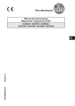
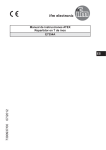
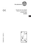
80008908/00 08/2014
ATEX operating instructions
T splitter stainless steel
E7354A
UK
Remarks for safe use in hazardous areas
Functions and features
• Use in hazardous areas according to the classification
II 3G
II 3D
(group II, category 3, apparatus for gas and dust atmosphere)
Complies with the standards EN60079-0, EN60079-15 and EN60079-31.
Marking
II 3G Ex nA II T6 Gc X
II 3D Ex tc IIIC T70°C Dc X
Installation / Set-up
The units must only be installed, connected and set up by qualified staff. The qualified staff must have knowledge of protection classes, regulations and provisions
for apparatus in hazardous areas.
Check whether the classification (see "marking" above and marking on the unit)
is suitable for the application. Adhere to the relevant national regulations and
provisions.
• Permissible operating temperature of the application:
0 ... +60°C
With the T splitter the AS-i voltage and external auxiliary voltage can be tapped via
the M2 socket (current rating 4 A).
Disconnect the power supply.
Important notes
Ensure when replacing the T splitter that the pierced points on the AS-i flat cable
are either used again or are placed within the black seal area of the T splitter.
If no connector is fitted to the M12 socket (tightening torque 0.6...0.8 Nm) ensure
that the protective cover is in place.
2
Tests with the following flat cables were carried out and passed successfully:
E74000, E74010, E74200, E74210 as well as all technically identical versions with
different lengths.
The E74100 and E74110 flat cables as well as all technically identical versions
with different lengths are not suited.
It is the responsibility of the operator to check the suitability of the flat cables for
use in hazardous areas, taking into account the environmental conditions (tempeUK
rature, chemicals, etc).
Mounting of the lower part
Select a flat mounting surface. Fix the lower part onto the mounting surface
(mounting holes 1); the mounting screws are not supplied. The supplied rubber
blanks should be used to seal unused cable ducts.
1
1
3
Insert the AS-i flat cable (yellow) into the "AS-i" cable duct and the 24 V flat cable
(black) into the other cable duct. Ensure correct positioning of the cables in the
profiled slot.
4
Mounting of the upper part
Put the upper part on the lower part and tighten the screws alternately (screws
supplied).
2
UK
1
1: M12 socket, tightening torque 0.6...0.8 Nm
2: Screws, tightening torque 2.5 Nm
Mounting drawing
Cable guide lower part
Take care in laying the AS-i flat cable, the flat cable should be laid straight for
about 15 cm.
15 cm
5
Wiring
1
4
2
3
5
M12 socket
Pin
AS-i +
1
0V
2
AS-i -
3
+24 V
4
not used
5
Special conditions for safe operation
•
•
•
•
•
•
•
•
•
•
•
•
•
6
Avoid electrostatic charging on plastic units and cables.
Do not mount the module in the dust flow.
Avoid dust deposits on the splitter box.
Avoid electrostatic charging, only clean the unit with a damp cloth. In principle,
rubbing with non-conductive materials must be avoided.
Avoid direct radiation with high UV components (sunlight), mount the unit in a
protected place.
The unit is rated for low impact energy (EN60079-0, table 8, 4 joules). Protect
splitter box and cable against destruction.
The unit with the M12 protective cover in place meets the requirements of the
categories 3D and 3G.
Use connectors which are suited for hazardous areas, e.g. ifm connectors
EVC**A with Ex certificate (certificate number BVS 08 ATEX E 109 U).
Do not separate the module upper part from the FC lower part while live.
Do not separate the M12 connectors when energised.
When connecting an M12 connector ensure that the O-ring is present and
undamaged in the socket.
Check the tightening torque of the screws two weeks after mounting and
retighten them, if necessary.
Protective caps, housing upper and lower parts and M12 fittings may only be
opened or closed in a sufficiently clean environment.
• For use in hazardous areas according to the indication compliance with the
protection rating is essential. Therefore appropriate care must be taken when
mounting the housing and the seals.
• Only use the supplied lower part and supplied seals.
• If only one cable duct is used, the other one has to be closed using the flat
cable blank.
• Flat cables must be firmly laid. Loads on the entry caused by strain or
UK
movement of the flat cables must be avoided.
Maintenance / Repair
The unit must not be modified nor can it be repaired. In case of a fault please
contact the manufacturer. The data sheet and the EC declaration of conformity are
available from the manufacturer on request.
7