1
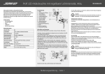
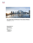
CH A P T E R
1
Troubleshooting the CTS 500-32
Revised: February 2012, OL-21845-01
You may want to periodically test system components using the hardware and software tests available in
the Cisco TelePresence System (CTS) Administration Troubleshooting window. This chapter contains
information about troubleshooting CTS 500-32 hardware and software.
Before You Begin
1.
Obtain your IP address in one of the following ways:
– From the CTS Cisco Unified IP phone touch the following softkeys:
Manual > more > Info
Tip
If you have more options on your phone, touch the more softkey until you reach the end of the
selections.
– From the Cisco TelePresence Touch 12 tap the following:
More > Status > System Status
Note
2.
Make a note of the IP address.
3.
Enter the IP address in your laptop’s browser window.
4.
Click Yes to accept all security connection messages.
You cannot perform diagnostics during an active Cisco TelePresence system call.
Proceed to the following sections to troubleshoot system components:
•
Adjusting the Camera, page 1-2
•
Testing the Display, page 1-2
•
Verifying Speaker Function, page 1-3
•
Verifying Microphone Function, page 1-4
•
Testing the Light Fixture, page 1-5
•
Testing Digital Media Player Audio, page 1-5
•
Troubleshooting the CTS 500-32, page 1-6
•
Where to Go Next, page 1-7
Cisco TelePresence System Administration Guide
OL-21845-01
1-1
Chapter 1
Troubleshooting the CTS 500-32
Adjusting the Camera
Note
The display used in this product contains mercury. Dispose of according to local, state, and federal laws.
Adjusting the Camera
Refer to the Cisco TelePresence System 500-32 Assembly, Use & Care, and Field-Replaceable Unit
Guide for complete camera management information:
Testing the Display
Different light sources and the amount of light in terms of lumens or watts produces different color
temperatures. These color temperatures are sometimes expressed using terms such as cool, warm, or
daylight, but can be expressed more precisely in kelvins (K) as a numeric value.
Note
Cisco recommends that you use lighting with a color temperature of 4000 to 4100 K.
Tip
In many cases, the color temperature is printed on the light bulb.
Note
If you are unable to determine the type and color temperature of light bulbs in the meeting room,
experiment with color temperature settings until the color and images on the display screen look lifelike.
Each time you change the setting and click Apply, the color temperature in the display changes. You
cannot see these changes until you enter loopback mode for the camera. See “Verifying Speaker
Function” section on page 1-3 to enter loopback mode.
To adjust a display:
Step 1
Log in to the Cisco TelePresence System.
Step 2
Choose Troubleshooting > Hardware Setup.
Step 3
Click the Displays radio button. A test image appears.
Step 4
Click Start in the Testing box to start the adjustment process. The Current Color Temperature test screen
appears, as shown in Figure 1-1.
Note
Each display in the meeting room should be showing a set of horizontal grey bars and that display's
relative position. The current color temperature setting is displayed.
Cisco TelePresence System Administration Guide
1-2
OL-21845-01
Chapter 1
Troubleshooting the CTS 500-32
Verifying Speaker Function
Figure 1-1
Color Temperature Test Screen
Step 5
Select the color temperature of the lighting in the meeting room from the drop-down menu. The Apply
button is activated.
Step 6
Click Apply.
Step 7
Click Stop to stop the test.
Verifying Speaker Function
To verify that the speakers are working properly and that the left and right speakers are not switched:
Step 1
Log in to the Cisco TelePresence System.
Step 2
Navigate to Troubleshooting > Hardware Setup > Speakers.
Step 3
Click Start to begin the speaker test. The speaker test screen appears, as shown in Figure 1-2
Cisco TelePresence System Administration Guide
OL-21845-01
1-3
Chapter 1
Troubleshooting the CTS 500-32
Verifying Microphone Function
Figure 1-2
Speaker Test Screen
Step 4
Click Cycle Through Speakers to have sound cycled automatically for 5 seconds on each speaker.
Step 5
Listen carefully as the sound moves from the left to the right speaker and watch the speaker icons on the
display.
Step 6
Make sure the sound from the speakers corresponds with the left and right speaker icons on the display.
Note
Step 7
You might have to move close to the display to determine the source of the sound.
Click Stop to end testing.
Verifying Microphone Function
Tip
During a call, the CTS 500-32 microphone can transmit ambient noise in the surrounding area, such as
other people talking in or near the same area. Make every effort to reduce or eliminate background noise
before you begin the test call.
To verify that the CTS 500-32 microphone array is working properly:
Step 1
Log in to the Cisco TelePresence System.
Step 2
Navigate to Troubleshooting > Hardware Setup > Microphones.
Step 3
Click Start to begin the test.
Step 4
Lightly tap the microphone on the underside of the display and watch the audio meter on the display to
make sure that the sound registers.
Cisco TelePresence System Administration Guide
1-4
OL-21845-01
Chapter 1
Troubleshooting the CTS 500-32
Testing the Light Fixture
Step 5
Click Stop to end the test.
Testing the Light Fixture
Use the following information to check the LEDs, light fixture, and configure the audio for the digital
media player (DMP).
Light
Each CTS 500-32 has a built-in light fixture. This troubleshooting feature lets you see or change the
status of the light.
Step 1
Navigate to Troubleshooting > Hardware Setup > Other Devices.
Step 2
Click the Light tab.
Step 3
Click the Start radio button to begin testing the light. If the light feature is enabled, the Light State On
button is highlighted. If the light feature is disabled, the Light State Off button is highlighted. Click the
Light State On or Light State Off button to change the current state of the light.
Step 4
To end the test, click Stop.
When you end the testing, the state of the light reverts to its default setting as specified in
Cisco Unified Communications Manager.
Testing Digital Media Player Audio
When you are not in a Cisco TelePresence call, the DMP feature allows you to use the DMP audio as the
secondary audio input source.
For more information about the DMP, see the Cisco Digital Media Players home page on Cisco.com.
To configure and test the DMP audio:
Step 1
Connect the DMP to the codec and display as follows:
•
Connect the DMP HD video cable to the HD Video input marked as “Auxiliary Input (ex. DMP)”
on the codec.
•
Connect the DMP audio cable to the Auxiliary PC Audio input on the codec.
Step 2
Navigate to Troubleshooting > Hardware Setup > Other Devices.
Step 3
Click the DMP tab.
Step 4
Click the Start button.
Step 5
Select one of the following radio buttons:
•
Select the DMP radio button if the audio that you connected to the codec is coming from a DMP.
•
If you are using a non-DMP source, select the PC radio button.
When Secondary Audio Input Source is set to DMP, audio input is active only when:
Cisco TelePresence System Administration Guide
OL-21845-01
1-5
Chapter 1
Troubleshooting the CTS 500-32
Troubleshooting the CTS 500-32
•
The CTS 500-32 is not in a call
•
The time period is during normal business hours
Note
Define normal business hours with the Display on Time and Display on Duration fields in
Cisco Unified Communications Manager. For information about configuring normal business
hours for your CTS 500-32, see the Cisco Unified Communications Manager Configuration
Guide for the Cisco TelePresence System.
When Secondary Audio Input Source is set to PC, the audio input is active while the presentation
source is active, both in and out of a call.
Step 6
To end DMP audio configuration or testing, click Stop.
The CTS 500-32 retains the setting that you just set.
Troubleshooting the CTS 500-32
Table 1-1
Troubleshooting the CTS 500-32
Problem
Possible Cause
Actions
Phone verification fails
during first-time setup.
The DHCP has dynamically allocated
a TFTP server address that is
different than the actual TFTP
address of the Unified
Communications Manager server for
your system.
To fix this problem, complete the following steps:
1.
Run the first-time setup wizard until you reach the
System Verification Complete Screen.
2.
Click the CTS Admin UI button to go to the
Cisco TelePresence Administration interface.
3.
Enter your username and password.
Tip
By default, the username is admin and the password
is cisco.
4.
Navigate to Unified CM Settings.
5.
Click the Specify radio button, which allows you to
change the TFTP server IP address.
6.
Change the TFTP server to the valid TFTP server
address for your system.
7.
Click Apply.
When running the First
Time Setup Wizard, the
Eye Height check box is
not checked.
This does not note a problem with the system. No action is
The check box for the Eye Height
Setup checklist on the left side of the required.
first-time setup wizard should be
checked. In some cases, however, the
box does not get checked.
Camera setup or
troubleshooting fails.
The room may be too dark.
Note
Add more light to the room and click Try Again to rerun the
camera setup procedure.
For more system troubleshooting information, see the Cisco TelePresence System Troubleshooting Guide on
Cisco.com.
Cisco TelePresence System Administration Guide
1-6
OL-21845-01
Chapter 1
Troubleshooting the CTS 500-32
Where to Go Next
Where to Go Next
For information about system messages that may appear on the Cisco TelePresence system, see the
Cisco TelePresence System Message Guide on the Cisco TelePresence Administration Software Error
and System Messages home page on Cisco.com.
See the First-Time Setup chapter of the Cisco TelePresence System 500-32 Assembly, Use & Care, and
Field-Replaceable Unit Guide for complete information about the CTS 500-32:
Cisco TelePresence System Administration Guide
OL-21845-01
1-7
Chapter 1
Troubleshooting the CTS 500-32
Where to Go Next
Cisco TelePresence System Administration Guide
1-8
OL-21845-01