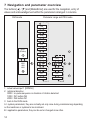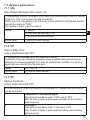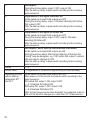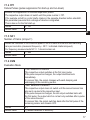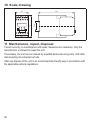
1
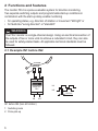
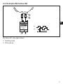
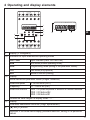
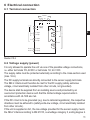
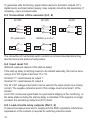
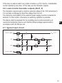
Operating instructions
Monitor FD-2
UK
DR2005
DR2006
7390342 / 01
07 / 2007
Content
1 Safety instructions�����������������������������������������������������������������������������������������������4
2 Functions and features����������������������������������������������������������������������������������������6
2.1 Example IN1 before IN2��������������������������������������������������������������������������������6
2.2 Example IN2 before IN1��������������������������������������������������������������������������������7
3 Operating principle����������������������������������������������������������������������������������������������8
4 Operating and display elements��������������������������������������������������������������������������9
5 Installation���������������������������������������������������������������������������������������������������������10
5.1 Mounting of the sensors:�����������������������������������������������������������������������������10
6 Electrical connection������������������������������������������������������������������������������������������ 11
6.1 Terminal connection������������������������������������������������������������������������������������� 11
6.2 Voltage supply (power)�������������������������������������������������������������������������������� 11
6.3 Connection of the sensors (In1, 2)��������������������������������������������������������������12
6.4 Input reset 1/2����������������������������������������������������������������������������������������������12
6.5 Load circuits relay outputs (Out1, 2)������������������������������������������������������������12
6.6 Load circuits transistor outputs (Out1, 2)�����������������������������������������������������13
6.7 Typical input circuit��������������������������������������������������������������������������������������13
7 Navigation and parameter overview������������������������������������������������������������������14
7.1 System parameters�������������������������������������������������������������������������������������15
7.1.1 SOx�����������������������������������������������������������������������������������������������������15
7.1.2 ST1�����������������������������������������������������������������������������������������������������15
7.1.3 SC1�����������������������������������������������������������������������������������������������������15
7.1.4 FP1�����������������������������������������������������������������������������������������������������17
7.1.5 NC1����������������������������������������������������������������������������������������������������17
7.1.6 EVM����������������������������������������������������������������������������������������������������17
7.1.7 DIM�����������������������������������������������������������������������������������������������������18
7.1.8 VER����������������������������������������������������������������������������������������������������18
7.2 Application parameters��������������������������������������������������������������������������������19
7.2.1 CTx�����������������������������������������������������������������������������������������������������19
7.2.2 DTx�����������������������������������������������������������������������������������������������������19
7.2.3 FTx�����������������������������������������������������������������������������������������������������19
8 Programming�����������������������������������������������������������������������������������������������������20
8.1 Programming example DT2 (delay time, output 2)��������������������������������������21
8.2 Notes on programming��������������������������������������������������������������������������������22
2
8.2.1 RUN mode������������������������������������������������������������������������������������������22
8.2.2 Time-out function��������������������������������������������������������������������������������22
8.2.3 Numerical entries��������������������������������������������������������������������������������22
8.2.4 Factory Reset�������������������������������������������������������������������������������������22
8.2.5 KEY function���������������������������������������������������������������������������������������23
9 Technical data����������������������������������������������������������������������������������������������������24
10 Scale drawing��������������������������������������������������������������������������������������������������26
11 Maintenance, repair, disposal��������������������������������������������������������������������������26
3
UK
These instructions apply to all units of the monitor type FD-2.
They are intended for authorised persons according to the EMC and low voltage
directives.
They are part of the unit. They contain information about the correct handling
of the product. Read them before use to familiarise yourself with operating
conditions, installation and operation. Follow the safety instructions.
1 Safety instructions
Follow the operating instructions. Non-observance of the instructions, operation
which is not in accordance with use as prescribed below, wrong installation or
incorrect handling can affect the safety of operators and machinery.
The installation and connection must comply with the applicable national and
international standards. Responsibility lies with the person installing the device.
The unit must only be installed, connected and put into operation by a qualified
electrician as
• during the installation dangerous contact voltage occurs and
• the safe function of the unit and the plant is only guaranteed when installation
is correctly carried out.
Disconnect the unit externally before handling it. Also disconnect any
independently supplied relay load circuits.
Be careful when handling the unit once power is applied. This is only allowed by
qualified personnel due to the protection rating IP 20.
The design of the unit corresponds to the protection class II except for the terminal
blocks. Protection against accidental contact (finger-touch to IP 20) for qualified
personnel is only guaranteed if the terminal screw has been completely screwed
in. For the correct operation the unit must be mounted in a housing (protection
rating IP 40 or higher) which can only be opened using a tool or in a locked control
cabinet.
If the unit has an external 24 V DC supply, this voltage must be generated and
supplied externally according to the requirements for safe extra-low voltage
(SELV) since this voltage is supplied without further measures near the operating
elements and at the terminals for the supply of connected pulse pick-ups.
The wiring of all signals in connection with the SELV circuit of the device must also
comply with the SELV criteria (safety extra-low voltage, safe electrical isolation
from other electric circuits).
4
If the externally supplied or internally generated SELV voltage is externally
grounded, the responsibility lies with the user in accordance with the applicable
national installation regulations. All statements in these operating instructions refer
to the unit the SELV voltage of which is not grounded.
It is not allowed to supply external voltage to the terminals for the pulse pick-up
supply.
The consumption of current which exceeds the value given in the technical data is
not allowed.
An external main switch must be installed for the unit which can switch off the unit UK
and all related circuits. This main switch must be clearly assigned to the unit.
As described in the technical specifications below the device can be operated in
a wide ambient temperature range. Because of the additional internal heating the
operating elements and the housing walls can have high perceptible temperatures
when touched in hot environments.
In case of malfunction of the unit or queries please contact the manufacturer.
Any tampering with the device can seriously affect the safety of operators and
machinery. This is not permitted and leads to an exclusion of liability and warranty.
5
2 Functions and features
The monitor FD-2 is a pulse evaluation system for direction monitoring.
Two separate switching outputs and programmable start-up conditions in
combination with the start-up delay enable monitoring
• for operating states, e.g. direction of rotation or movement "left/right" or
• for faults like "wrong direction" or "standstill".
WARNING
The FD-2 monitor is a single-channel design. Using an electrical connection of
the outputs of two or more units to achieve a redundant circuit, they can also
be used for safety-related tasks. All applicable technical standards must be
followed.
2.1 Example IN1 before IN2
IN 1
IN 2
MONITOR
FD-2
OUT 1
OUT 2
ON
OFF
IN1 before IN2 (here left rotation)
1: Switching cams
2: Pulse pick-up
6
IN1
IN2
≥ 0,25 ms
2.2 Example IN2 before IN1
IN 1
UK
IN 2
MONITOR
FD-2
OUT 1
OUT 2
OFF
EIN
IN1
IN2
≥ 0,25 ms
IN2 before IN1 (here right rotation)
1: Switching cams
2: Pulse pick-up
7
3 Operating principle
The monitor takes pulses of external pulse pick-ups at 2 separate input channels,
evaluates their time offset and switches the 2 outputs according to the set
parameters.
In principle, it can be said:
• for the pulse sequence IN1 before IN2 output 1 switches,
i.e. relay 1 is energised, transistor output 1 is switched. (Relay 2 is deenergised, transistor output 2 is blocked.)
• for the pulse sequence IN2 before IN1 output 2 switches,
i.e. relay 2 is energised, transistor output 2 is switched. (Relay 1 is deenergised, transistor output 1 is blocked.)
Even in case of a temporary standstill the output remains switched
• until the pulse sequence changes or
• until the output is reset by the programmable reset time or
• until the operating voltage is switched off.
The display indicates the current rotational speed [RPM] or input frequency [Hz] at
the input channel IN1 or the last detected pulse sequence [0/1/2DIR].
0DIR = no pulse sequence or direction of rotation detected
1DIR = pulse sequence IN1 before IN2
2DIR = pulse sequence IN2 before IN1
Please note:
The input pulses must be phase-shifted and overlap for about 0.25 ms.
8
4 Operating and display elements
UK
1
1a
1b
1c
2
Display (7/14-segment)
Indicators for input channels and operating modes
CH1...CH4
Input channels (here: CH1 and CH2)
RUN
Run mode (normal operating mode)
PRG
Programming mode (setting of the parameter values)
TST
Test mode (only opitonal)
KEY
Status of the unit (locking)
Display
Actual values and parameter values (5 digits, numerical)
Rotational speed
0...60.000 RPM (CH1)
Frequency
0.1...1000.0 Hz (CH1)
Rotational direction
0DIR = no pulse sequence or direction of rotation detected
1DIR = IN1 before IN2
2DIR = IN2 before IN1
Outside the value ranges the display shows "----".
Display
Parameter abbreviation and units (3-digit, alphanumeric)
[▲] and [▼] buttons
Selection of the actual value display, parameter selection, setting of the parameter
values
9
3
4
5
6
[Mode/Enter] button
Selection of the operating mode, acknowledgement of the parameter value, front
reset
LED In1/2 (yellow)
Input pulses
LEDs Out1/2 (green) Switching status of the outputs 1 and 2
Off
Output is not switched
(relay de-energised, transistor blocked)
On
Output is switched
(relay energised, transistor switched)
Flashing quickly
Output is kept latched
(parameter SOx, Store Output)
Flashing slowly
The delay time is effective for the output. The output switches
when the delay time has elapsed and the trigger event is still
present (parameter DTx, delay time).
Panel for labelling
5 Installation
Mount the unit on a DIN rail or by means of a mounting base. Leave enough
space between the unit and the top and bottom of the control cabinet to enable air
circulation and to avoid excessive heating.
Take into account the internal heating of all units when mounting several units side
by side. The environmental conditions must be observed for every unit.
5.1 Mounting of the sensors:
Adhere to the installation instructions of the manufacturer.
10
6 Electrical connection
6.1 Terminal connection
Power
AC/DC or
7 8
5
6
Sensor
supply
DC
1 2
3
16
In 1
In 2
4 pnp
10 npn
11 pnp
12 npn
Reset 1
17 pnp
Reset 2
18 pnp
15
13
14
24
UK
Out 1
Out 2
21
19
20
Monitor FD-2
6.2 Voltage supply (power)
It is only allowed to operate the unit via one of the possible voltage connections,
i.e. either terminals 7/8, AC/DC or terminals 1/2; 24 V DC.
The supply cable must be protected externally according to the cross-section used
(max. 16 A).
The DC supply terminals are directly connected to the sensor supply terminals.
The SELV criteria must therefore be met for the DC supply (safety extra-low
voltage, circuit electrically isolated from other circuits, not grounded).
The device shall be supplied from an isolating source and protected by an
overcurrent protection device such that the limited voltage requirements in
accordance with UL 508 are met.
If the DC circuit is to be grounded (e.g. due to national regulations), the respective
directives must be adhered to (safety extra-low voltage, circuit electrically isolated
from other circuits).
If the unit is supplied on AC, the low voltage provided for the sensor supply meets
the SELV criteria according to EN 61010, overvoltage category II, soiling degree 2.
11
To guarantee safe functioning, signal cables (sensors, transistor outputs, 24 V
digital inputs) and load cables (supply, relay outputs) should be laid separately. If
necessary, use a screened cable.
6.3 Connection of the sensors (In1, 2)
DC PNP
BN
BN
BK
BK
BU
BU
DC NPN
5
45
4
11
11
6
6
DC quadronorm
WH
WH
BK
BK
BN
BN
BK
BK
BU
BU
AC/DC
5
105
10
12
12
6
6
BN
BN
5
5
BU
BU
4
11
4
11
NAMUR up to 25 V
5
5
BN
BN
10
12
10
12
4
11
4
11
BU
BU
6
6
The connection of mechanical switch contacts is not recommended since they
tend to bounce and produce faulty pulses.
6.4 Input reset 1/2
(External reset and release of the start-up delay)
If the start-up delay or latching reset is to be started externally, this can be done
using a 24 V DC signal at terminal 17 or 18.
Terminal 17 = reset/release for output 1
Terminal 18 = reset/release for output 2
The 24 V DC voltage at terminal 5 can be used for the reset inputs via a closing
contact. The negative reference point of this voltage must be terminal 1 of the
monitor.
A 24 V DC continuous signal leads to a permanent bridging of the monitoring, i.e.
the same state as during the start-up delay is indicated. If the signal is no longer
provided, the set start-up delay time (ST1) starts.
6.5 Load circuits relay outputs (Out1, 2)
To prevent excessive wear and to comply with the EMC regulations interference
suppression of the contacts is required for switching inductive loads.
12
If the relay is used to switch very small currents (e.g. PLC inputs), considerable
contact resistance can arise. In this case use the transistor outputs.
6.6 Load circuits transistor outputs (Out1, 2)
The transistor outputs need a common external voltage of 24 V DC at terminal 3.
It is normally not allowed to take this voltage from the unit.
The reference point (GND) of the external power supply must be connected to
terminal 1 of the monitor, otherwise no switching operation is possible.
The device shall be supplied from an isolating source and protected by an
UK
overcurrent protection device such that the limited voltage requirements in
accordance with UL 508 are met.
6.7 Typical input circuit
70E
UBB (24 V)
+ sensor supply
ϑ
47n
2K2
4K7
270E
10K
npn
1n0
4K7
10n0
10K
270E
pnp
1n0
2K2
4n7
- sensor supply
13
7 Navigation and parameter overview
The buttons [▲] / [▼] and [Mode/Enter] are used for the navigation, entry of
values and acknowledgement within the parameters arranged in columns.
RUN mode
Parameter range and PRG mode
VER
DIM
EVM
NC1
FP1
input 1
[RPM/Hz)
0DIR
1DIR
2DIR
SC1
A
ST1
SO1
SO2
CT1
CT2
DT1
DT2
B
FT1
FT2
1: actual value input 1 [RPM/Hz]
2: rotational direction
0DIR = no pulse sequence or direction of rotation detected
1DIR = IN1 before IN2
2DIR = IN2 before IN1
3: back to the RUN mode
A = system parameters; they are normally set only once during commissioning depending
on the machines or systems to be monitored.
B = application parameters; they can be set or changed more often.
14
7.1 System parameters
7.1.1 SOx
Store Output (latching function outputs 1/2)
If the parameter is active, the outputs do not switch back automatically in case of a change
of direction. They must be reset internally or externally.
NOTE: A reset is only possible in the Run mode. A reset deletes the last detected direction
and sets the display to "0DIR".
SO1 applies to output 1, SO2 to output 2.
Values
0 = inactive
UK
1 = front reset ([Mode/Enter] > 3 s)
2 = front reset and external reset
Default value
0 (latching function inactive)
7.1.2 ST1
Start-up Delay Time
(only in combination with SC1)
To suppress error messages when an installation is started.
Irrespective of the input pulses the respective output is switched during the set time as
defined by the following parameter SC1 when the unit has been switched on or the 24 V
signal has been removed from the reset input.
Values
0.0...1000.0 s
Default value
0.0 (start-up delay inactive)
7.1.3 SC1
Start-up Conditions
(only in combination with ST1)
In combination with the start-up delay and the parameter SC1 defined start-up conditions
can be determined.
1
Suppression of the direction signal
During the start-up delay: output 1 OFF, output 2 OFF
After the start-up delay: outputs switch according to the incoming
pulse sequence
2
Set output 1
During the start-up delay: output 1 ON, output 2 OFF
After the start-up delay: outputs switch according to the incoming
pulse sequence
15
3
4
5
6
Values
Default value
Operating principle
without start-up
parameters ST1
and SC1:
16
Set output 2
During the start-up delay: output 1 OFF, output 2 ON
After the start-up delay: outputs switch according to the incoming
pulse sequence
Suppression of the signal IN2 before IN1
At the switch-on moment both outputs are OFF
During the start-up delay: output 1 ON when detecting IN1 before
IN2, output 2 OFF
After the start-up delay: outputs switch according to the incoming
pulse sequence
Suppression of the signal IN1 before IN2
At the switch-on moment both outputs are OFF
During the start-up delay: output 1 OFF, output 2 ON when
detecting IN2 before IN1
After the start-up delay: outputs switch according to the incoming
pulse sequence
Set outputs 1 and 2 until the first detection of direction
At the switch-on moment both outputs are ON
During the start-up delay: after the first detection of direction the
"wrong" relay de-energises, e.g. if IN1 before IN2, output 1 remains
ON and output 2 changes to OFF
After the start-up delay: outputs switch according to the incoming
pulse sequence
1...6
1 (suppression of the direction signal during the start-up delay)
At the switch-on moment both outputs are OFF.
After power on of the monitor the outputs switch according to the
pulse sequence.
IN1 before IN2: output 1 ON, output 2 OFF
(→ 2.1 Example IN1 before IN2)
IN2 before IN1: output 1 OFF, output 2 ON
(→ 2.2 Example IN2 before IN1)
After an input sequence has been detected, the respective output is
ON until the direction changes or a reset time (CT1) has been set.
7.1.4 FP1
Failure Pulses (pulse suppression for start-up and run-down)
Enables the suppression of direction-dependent pulses.
The respective output does not switch until the pulse number > FP1.
If for example a shaft or a rotor briefly rotates in the opposite direction before standstill,
this parameter prevents that a change of direction is signalled.
This is also so for the first start-up.
Values
0...100
Default value
0
UK
7.1.5 NC1
Number of Cams (at input 1)
Allows the indication of the rotational speed in RPM if there is more than one switching
cam per revolution (measured frequency ÷ NC1 = indicated rotational speed).
For frequency measurements NC1 = 1 should remain set.
Values
1...999
Default value
1
7.1.6 EVM
Evaluation Mode
0
1
Values
Default value
"Fast" detection of direction
The respective output switches at the first input pulse.
If the pulse sequence changes, the output switches back
immediately.
If a sensor fails, the output changes with each damping and
undamping of the remaining sensor.
"Safe" detection of direction
The respective output does not switch until the second sensor has
also sent a pulse to the respective input.
If the pulse sequence changes, the set output switches back with
the first pulse; the output which is not set only switches after a pulse
of the second sensor.
If a sensor fails, the output switches back after the first pulse of the
remaining sensor and remains OFF.
0, 1
1 (reliable detection of direction)
17
7.1.7 DIM
Dimension (display format)
Indication in RPM (revolutions per minute) or Hz
Values
Default value
0 = RPM
1 = Hz
0 (RPM)
7.1.8 VER
Software version
Possibility to check which software version is installed
(5-digit number with the abbreviation VCO)
18
7.2 Application parameters
7.2.1 CTx
Cycle Time (reset time for output 1/2)
The respective output switches back if within the set reset time no direction-dependent
pulses have been detected.
With inactive reset time (0.0 s) the output remains switched according to the pulse
sequence last detected.
(→ 3 Operating principle)
CT1 applies to output 1, CT2 to output 2.
Values
0.0...1000.0 s
Default value
0.0 (no reset time, respective output remains switched)
UK
7.2.2 DTx
Delay Time (for output 1/2)
Enables a delayed switching of the outputs 1/2.
The respective output does not switch until the set delay time has elapsed and the
detected pulse sequence continues.
The delay time is only effective for switching, not for switching back the respective output.
DT1 applies to output 1, DT2 to output 2.
Values
0.0...1000.0 s
Default value
0.0 (no delay time)
7.2.3 FTx
Fleeting Time (for outputs 1/2)
If a pulse sequence is detected, the output changes its state during the set time and then
switches back to the initial state.
NOTE: It is not useful to activate a fleeting time and the latching function SOx for an output
at the same time.
FT1 applies to output 1, FT2 to output 2.
Values
0.0...1000.0 s
Default value
0.0 (no fleeting time, respective output switches statically)
19
8 Programming
WARNING
If programming takes place during operation, dangerous contact voltage may
occur. Therefore ensure that programming is done by a qualified electrician.
Parameter changes during operation, especially changes to the switching
function and the switch points can lead to malfunction in the plant.
Therefore disconnect it during the change and then check the function.
Programming consists of 6 steps:
1. Change from the RUN mode to the parameter range 1 or 2
2. Select the requested parameter (SO1, ST1, SC1, etc.)
3. Change to the PRG mode
4. Set or change the parameter value
5. Acknowledge the set parameter value
6. Return to the RUN mode
20
[Mode/Enter]
[▲] / [▼]
[Mode/Enter]
[▲] / [▼]
[Mode/Enter] > 3 s
[Mode/Enter] > 3 s
8.1 Programming example DT2 (delay time, output 2)
Operation
Change from the RUN mode to the parameter range (here 2)
►► Briefly press [Mode/Enter] twice.
>> The 2nd parameter range is displayed.
Selection of the requested parameter (here DT2)
►► Press the [▼] button until the parameter DT2 is
displayed with the current set value (here default
value 0.0).
Change to the PRG mode
►► Briefly press [Mode/Enter] once.
>> The unit is in the programming mode.
>> PRG indicator visible, parameter abbreviation
flashes.
Set or change the parameter value
►► Press the [▲] / [▼] buttons until the requested
parameter value is indicated.
(→ 8.2.3 Numerical entries)
Acknowledge the set parameter value
►► Press [Mode/Enter] until the parameter abbreviation no longer flashes and the indicator PRG has
disappeared.
>> The new parameter value is indicated and
effective.
Return to the RUN mode
►► Press [Mode/Enter] for about 3 s or wait for the
time-out function (approx. 15 s).
>> The unit is again in the RUN mode, the current
value is indicated.
Display
CH2
RUN
CH2
RUN
UK
CH2
RUNPRG
CH2
RUNPRG
CH2
RUN
CH2
RUN
21
8.2 Notes on programming
8.2.1 RUN mode
During programming the unit internally remains in the RUN mode
(RUN indicator visible). This means that until a new value is acknowledged
with [Mode/Enter], the unit carries out its monitoring function on the basis of
the previously set parameters and switches the relay and transistor outputs
accordingly.
The monitoring function of the monitor is deactivated by continuously
pressing [Mode/Enter] in the RUN mode. The deactivation is effective as
long as the button is pressed.
8.2.2 Time-out function
If during programming no pushbutton is pressed for approx. 15 s, this is seen as a
cancellation.
Parameter changes which are not acknowledged with [Mode/Enter] are rejected.
The previously set parameter value is restored and remains effective for the
monitoring functions.
8.2.3 Numerical entries
Press [▲] or [▼] and hold the button.
The smallest decade becomes active and is counted up or down depending on the
selected pushbutton (e.g. 1, 2, 3,...0). Then comes the next decade, etc.
As soon as the pushbutton is released, the active decade flashes. It is set by
pressing [▲] or [▼] several times. The preceding decade then flashes and can be
set.
8.2.4 Factory Reset
The factory default values can be restored by pressing [▲] and [▼] simultaneously
during power on. All previously entered parameter values are lost.
22
8.2.5 KEY function
The unit can be locked to prevent incorrect entries.
Locking
►► Press [▲] and [▼] simultaneously
and hold the buttons pressed.
>> The KEY indicator flashes.
►► Release the pushbuttons when
the KEY indicator is continuously
indicated.
Unlocking
►► Press [▲] and [▼] simultaneously
and hold the buttons pressed.
>> The KEY indicator flashes.
►► Release the buttons when the KEY
indicator is no longer indicated.
UK
23
9 Technical data
Power supply
Supply voltage AC/DC:
Frequency
Supply voltage DC
Voltage tolerance
Power consumption
Sensor inputs
Sensor types
Sensor supply
Load current sensor input
Current consumption sensor
Switch point for PNP pulse pick-up
Switch point for NPN pulse pick-up
Input frequency (max.)
Characteristic values
Accuracy of the frequency
measurement
Power-on delay time
Reset/release inputs 1/2
External auxiliary voltage
Current consumption
Switch point for positive switching
Outputs
Relay outputs (Out1, 2)
Switching capacity
Relay switching times
Cycles
Transistor outputs (Out1, 2)
24
DR2005
DR2006
110...240 V AC/DC
23...60 AC/DC
50...60 Hz
27 V DC (typ. 24 V DC)
-20...+10 %
AC/DC input: 5 VA / DC input: 3 W
PNP/NPN; NAMUR (24 V DC)
24 V DC; short-circuit proof and overload protected
approx. 10 mA
max. 15 mA
> 12 V ON; < 5 V OFF
> 15 V OFF; < 8 V ON
max. 1 kHz
(input pulses must be phase-shifted and overlap for
about 0.25 ms)
< 1%
300 ms (this corresponds to the display refresh
time)
24 V DC
typ. 2.5 mA
> 14 V
2 changeover contacts; potential-free
6 A (250 V AC); B300, R300
10...20 ms (energising), 30...40 ms (deenergising)
> 107 (without load)
3 x 10⁵ (250 V AC, 4 A, ohmic resistance)
PNP switched; externally supplied; short-circuit
proof
Switching voltage/switching
current
Device details
Housing
Dimensions (H x W x D)
Weight
Protection housing / terminals
Connection
Display
Environmental conditions
Ambient/storage temperature
Air pressure
Permissible relative air humidity
Maximum operating altitude
cULus test conditions
CE marking
24 V DC (± 20 %) / max. 15 mA
Housing for DIN rail mounting; plastic
78 x 45 x 120 mm
490 g
IP 50/20
21 dual-chamber terminals;
2 x 2.5 mm² (AWG 14)
LC display: 7/14-segment
UK
-20...+60°C / -25...+80°C
75...106 kPa
max. 75 % (35°C)
2000 m above sea level
Housing dimensions for temperature rise test:
200 x 200 x 150 mm
according to EN 61010 (1993); +A2 (1995; EMC
89/336/EEC), EN 50081-1; EN 61000-6-2
25
10 Scale drawing
120
2
3
4
5
6
7
8
9
10
11
12
13
14
15
16
17
18
19
20
21
22
23
24
78
1
35,5
45
11 Maintenance, repair, disposal
If used correctly, no maintenance and repair measures are necessary. Only the
manufacturer is allowed to repair the unit.
If necessary, the unit can be cleaned by qualified personnel using a dry cloth after
disconnecting all connected circuits.
After use dispose of the unit in an environmentally friendly way in accordance with
the applicable national regulations.
26