1
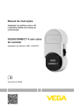
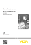
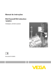
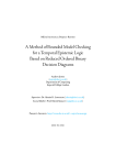
Operating Instructions
WEB-VV VH
Configuration, first steps
Indication
and adjustment
Contents
Contents
1
About this document
1.1
1.2
1.3
2
.
.
.
.
.
.
.
.
.
.
.
.
.
.
.
.
.
.
.
.
.
.
.
.
.
.
.
.
.
.
.
.
.
.
.
.
.
.
.
.
.
.
.
.
.
.
.
.
.
.
.
.
.
.
.
.
.
.
.
.
.
.
.
.
.
.
.
.
.
.
.
.
.
.
.
Prerequisites . . . . . . . . . . . . . . . . . . . . . . . . . . . . . .
Start WEB-VV the first time . . . . . . . . . . . . . . . . . . . .
7
8
User accounts . . . . . . . . . . . . . . . . . . . . . . . . . . . . .
14
Definition message/notification. . . . . . . . . . . . . . . . . .
Notifications via e-mail . . . . . . . . . . . . . . . . . . . . . . .
Notification via SMS/fax . . . . . . . . . . . . . . . . . . . . . .
16
18
19
Further configuration options
7.1
8
5
5
.
.
.
.
.
Messages and notifications
6.1
6.2
6.3
7
Scope of delivery . . . . . . . . . . . . . . . . . . . . . . . . . . .
What is VMI/WEB-VV? . . . . . . . . . . . . . . . . . . . . . . .
.
.
.
.
.
User administration
5.1
6
4
4
4
4
4
.
.
.
.
.
Operation
4.1
4.2
5
..
..
..
..
..
Authorised personnel . . . .
Appropriate use . . . . . . . .
Warning about misuse . . .
General safety instructions
Environmental instructions.
Product description
3.1
3.2
4
3
3
3
For your safety
2.1
2.2
2.3
2.4
2.5
3
Function. . . . . . . . . . . . . . . . . . . . . . . . . . . . . . . . . .
Target group . . . . . . . . . . . . . . . . . . . . . . . . . . . . . .
Symbolism used. . . . . . . . . . . . . . . . . . . . . . . . . . . .
Layout . . . . . . . . . . . . . . . . . . . . . . . . . . . . . . . . . . .
20
Supplement
8.1
License agreement . . . . . . . . . . . . . . . . . . . . . . . . . .
21
35069-EN-081201
2
WEB-VV VH • Configuration, first steps
1 About this document
1 About this document
1.1 Function
This operating instructions manual provides all the information you
need for installation and setup. Please read this information before
setting up the instrument and keep this manual accessible in the
immediate vicinity of the device.
1.2 Target group
This operating instructions manual is directed to trained qualified
personnel. The contents of this manual should be made available to
these personnel and put into practice by them.
1.3 Symbolism used
Information, tip, note
This symbol indicates helpful additional information.
Caution: If this warning is ignored, faults or malfunctions can
result.
Warning: If this warning is ignored, injury to persons and/or serious
damage to the instrument can result.
Danger: If this warning is ignored, serious injury to persons and/or
destruction of the instrument can result.
Ex applications
This symbol indicates special instructions for Ex applications.
l
à
Action
This arrow indicates a single action.
Sequence
Numbers set in front indicate successive steps in a procedure.
35069-EN-081201
1
List
The dot set in front indicates a list with no implied sequence.
WEB-VV VH • Configuration, first steps
3
2 For your safety
2 For your safety
2.1 Authorised personnel
All operations described in this operating instructions manual must be
carried out only by trained specialist personnel authorised by the plant
operator.
2.2 Appropriate use
WEB-VV is a WEB portal for simple recording, presentation and
transmission of measured values. Measured values can be transmitted
via Internet, telephone lines or GSM network to the WEB-VV server.
2.3 Warning about misuse
Improper or unconventional use can lead to application-specific
dangers. The displayed measured values must only be used for
visualisation and inventory monitoring. Automatic monitoring for overfill
(overfill protection), for example, is not allowed.
2.4 General safety instructions
Installation and use of the software are carried out at your own risk. We
do not accept liability for consequential damage.
2.5 Environmental instructions
Protection of the environment is one of our most important duties. That
is why we have introduced an environment management system with
the goal of continuously improving company environmental protection.
The environment management system is certified according to DIN
EN ISO 14001.
Please help us fulfil this obligation by observing any environmental
instructions that may be in this manual.
35069-EN-081201
4
WEB-VV VH • Configuration, first steps
3 Product description
3 Product description
3.1 Scope of delivery
Scope of delivery
l
l
WEB-VV contact data
WEB-VV license agreement
3.2 What is VMI/WEB-VV?
VMI
VMI stands for Vendor Managed Inventory (supplier-controlled
inventory). The supplier is responsible for the inventory of his products
at the customer's location. He takes over inventory monitoring via
remote enquiry and autonomously controls the delivery of replenishments.
WEB-VV
WEB-VV stands for simple remote enquiry, user-friendly visualisation
and long-term data archiving. Thanks to its interfaces to standard
inventory control systems (ERP systems) as well as its comprehensive
notification functions, WEB-VV is the ideal basis for all VMI solutions.
WEB-VV is based on modern Web technologies, visualisation is
carried out via any standard browser such as e.g. the Internet Explorer.
This is possible in the local network as well as world-wide via Internet.
A local installation of application software for measured value
indication is hence not necessary. The transmission of measured
values is either carried out via LAN, Internet, GSM/GPRS or telephone
line. The protected area for measured value indication is only
accessible with an individual password, the connection is established
via the secure https protocol.
The measured values are provided by on-site sensors and collected
and further processed by appropriate VEGA signal conditioning
instruments. These signal conditioning instruments transmit (timecontrolled) the measured values to the defined WEB-VV server. The
indication of the measured values can be a bar graph or a table. Apart
from the current measured values, history data are also available. The
current measured values can be sent cyclically at any time also via email/SMS/fax. Event-controlled notification can also be configured.
WEB-VV is available in two versions, centrally hosted at VEGA or
locally installed at the customer's location.
At its own computer centre VEGA provides the server for adminstration of the inventory data. Through interruption-free power supply,
redundant hardware and automatic backup, 24-hour availablility is
guaranteed 365 days per year. Installation, administration and future
software updates are included in the one-time installation fee.
35069-EN-081201
Hosting at VEGA
WEB-VV VH • Configuration, first steps
5
3 Product description
Hosting locally
VEGA provides the instrument technology and software. Installation,
setup and adminstration are carried out by the customer. Operation as
well as maintenance, backup and software update also lie within the
customer's responsibility. The precondition is that the customer must
have his own IT infrastructure with appropriately qualified personnel.
35069-EN-081201
6
WEB-VV VH • Configuration, first steps
4 Operation
4 Operation
4.1 Prerequisites
The following prerequisites must be fulfilled in order to use WEB-VV:
WEB-VV contact data
You receive this document with the order confirmation. Enter your
company data, including an appropriate contact person. A contact for
the user account of the supervisor is also required. Please send the
contact data to the fax number given in the form.
WEB-VV license agreement
After sending in the contact data, you receive the license agreement.
This agreement includes the services, the duties and the liabilities of
both parties. The access data for the first login are also included.
Setup device network
A device network consists of a signal conditioning instrument
VEGAMET/VEGASCAN/PLICSRADIO with connected sensors and
the respective measurement loops. If signal conditioning instruments
are integrated via Ethernet interface into a company network with
internet access, the measured values can be transmitted directly via
http (Port 80) to the WEB-VV server. If the measured values should be
transmitted via modem (analogue/ISDN/GSM/GPRS), an appropriate
communication device is also required. In addition, the access data of
a provider are required in order for the signal conditioning instrument
to gain access to the Internet.
35069-EN-081201
Set up the signal conditioning instrument with PACTware according to
the respective instructions manual as well as the online help available
in PACTware and start a test transmission of the measured values.
Fig. 1: Test transmission WEB-VV measured values
WEB-VV VH • Configuration, first steps
7
4 Operation
Contact the WEB-VV administrator after setting up the device network.
The administrator then assigns the new device network accordingly
and releases the measured values for indication.
4.2 Start WEB-VV the first time
WEB-VV registration
Start your web browser and enter the URL: https://web-vv.vega.com.
Enter the access data from the User Agreement in the entry screen. As
an alternative, you can visit a demo plant to get acquainted with the
program - for this you do not need a password.
Fig. 2: WEB-VV registration
Adjustment system
The WEB-VV user interface is divided into different sections. These
sections fulfil the functions described below:
35069-EN-081201
8
WEB-VV VH • Configuration, first steps
4 Operation
Fig.
1
2
3
4
5
l
l
l
l
l
35069-EN-081201
First steps
Create a project
3: WEB-VV adjustment interface
Dynamic navigation section
Static navigation section
Breadcrumb navigation
Identification section
Information and application section
Dynamic navigation section: Shows the respective menu items
in dependence on the respective level
Static navigation section: Offers the options of global settings
such as language, time and password
Breadcrumb navigation: Shows the path of the current page,
provides the option to jump back to higher levels
Identification section: Informs you on the current application
level and shows the name of the plant operator, project and
measured value view.
Information and application section: Shows the measured
values or allows user-specific settings and selection options
The following steps are the minimum requirement for a measured
value indication:
1
Create a project: A project includes the assignment of a device
network, the user administration as well as the actual visualisation.
2
Assignment of a device network: Each device network stands
for a signal conditioning instrument with one or several measurement loops as well as a data transmission facility.
3
Create a measured value view: The measured value view
defines which measurement loops of a signal conditioning
instrument are combined into a group and made available for
visualisation.
The creation of a corresponding project is required for measured value
indication. Generally it is useful to create an individual project for each
end customer. To do this select the menu item "Projects" and click the
WEB-VV VH • Configuration, first steps
9
4 Operation
button "Add". Choose as project name e.g. the plant name or the
customer name. Fill in the other required fields and save your settings
via the button "Save and quit".
Fig. 4: Create a WEB-VV project
Assign a device network
After the device network has been set up on site and the measured
values have been transmitted to the WEB-VV server, the WEB-VV
administrator releases the device network to the WEB portal on your
request. Now all prerequisites are fulfilled and you can assign the
desired device network to one or several projects. If a device network
is not assigned to a project, a measured value view is not possible.
Therefore select the menu item "Device networks" in the left navigation
area. You will now see a list of all available device networks.
Fig. 5: List of the available device networks
After you have selected the desired device network, you will see in the
opening window all relevant details of this device network.
35069-EN-081201
10
WEB-VV VH • Configuration, first steps
4 Operation
Fig. 6: Device network details
Push the button "Assign device network" and assign one of the listed
projects to the device network. Save your selection via the button
"Save and quit".
Fig. 7: Assignment project -> Device network
Select the desired project and click the button "Add". Enter an
appropriate name for the measured value view and click to "Continue".
35069-EN-081201
Create measured value
views
WEB-VV VH • Configuration, first steps
11
4 Operation
Fig. 8: Create measured value view
Select the requested measurement loops from the list. Max. eight
measurement loops are possible per measured value view. Save your
selection via the button "Save and quit".
Fig. 9: Selection of measurement loops in a measured value view.
Show measured values
Select the desired project. You now get a list of all available measured
value views. Click to the requested measured value view. Now you
see the current measured values in a bar chart. In the left navigation
area, you can either select the tabular form or a display of the history
values. Here you will also find the display and configuration of
messages and information.
35069-EN-081201
12
WEB-VV VH • Configuration, first steps
4 Operation
35069-EN-081201
Fig. 10: Measured value view
WEB-VV VH • Configuration, first steps
13
5 User administration
5 User administration
5.1 User accounts
WEB-VV offers different user accounts that contain certain functions,
tasks and rights. The following user modes are available:
Supervisor
The supervisor is the contact person and is responsible for all
concerns in a company or in a facility. He has all rights on the plant
operator level. The supervisor is e.g. allowed to:
l
l
l
l
l
l
l
Create/modify/delete projects
Assign device networks
Configure SMS and fax providers
Create/modify/delete user accounts (main user/user)
Create/modify/delete measured value views
Create notification transmission
Create/modify/delete locations
Each WEB-VV supervisor can create additional user accounts on his
own. The supervisor account should generally not be used for
presentation of measured values - it is mainly designated for creation
and configuration.
Main user
The main user is responsible for a certain project of a plant operator.
Within this project, he has the same rights as a supervisor. The main
user is e.g. allowed to:
l
l
l
Create/modify/delete user accounts (user)
Create/modify/delete measured value views
Create notification transmission
User
A user has only read authorisation for the projects and measured value
views. It is the recommended user account for measured value
indication during operation.
Establish a user account
To establish a user account, you have to navigate into the menu "User
accounts" and select the button "Add". Enter the necessary data into
the entry mask and then click to the button "Continue". Take note of
capital and small letters when entering "User" and "Password"
because this is checked in both fields (case-sensitive).
35069-EN-081201
14
WEB-VV VH • Configuration, first steps
5 User administration
Fig. 11: Create a new user account
35069-EN-081201
Assign the user account to a plant operator and a project. Via the
listbox "Function" you select the respective user role. Save your
selection with "Save and quit".
WEB-VV VH • Configuration, first steps
15
6 Messages and notifications
6 Messages and notifications
6.1 Definition message/notification
Messages
Messages are a list of events and messages and are divided into the
following categories:
Faults
A fault is signalled by a yellow warning triangle in the upper right corner
below the measured value view. By clicking on the warning triangle
you automatically reach the fault list. Here, you get further information
about the current fault. Via the button "Mark as read" you confirm the
message. The yellow warning triangle remains until all messages of
the fault list are acknowledged.
A fault message can be caused by the following:
l
l
l
Communication failures between WEB-VV and signal conditioning
instrument, e.g. a missing data transmission
Measured value status faulty, e.g. sensor or measurement loop
out of order (E013)
Measurement loop in simulation
Alarms
An alarm is generated by WEB-VV when a defined value exceeded or
underrun. This is shown in the measured value graphic by a colour
change and presentation of the exceeded or underrun limit value of the
affected measurement loop. In addition, there is an entry under
"Alarms" in the message section. Via the button "Acknowledge“ the
alarm message can be acknowledged by the logged on user with the
current time stamp.
Transmission list
In the transmission list, all notifications sent by the system via e-mail/
SMS/fax are listed. The list includes successful as well as failed
transmissions.
35069-EN-081201
16
WEB-VV VH • Configuration, first steps
6 Messages and notifications
Fig. 12: Message list: Faults
Notifications
35069-EN-081201
Notifications are messages and information sent via e-mail/SMS/fax or
outputted on the screen. They are divided into the following categories:
Actual measured values
Actual measured values are sent as notification. They can be sent time
as well as event controlled via e-mail/SMS/fax.
Alarms
An alarm is not only registered automatically under "Messages" but
can also be sent via e-mail/SMS/fax.
Faults
A fault is not only registered automatically under "Messages" but can
also be sent via e-mail/SMS/fax.
Fig. 13: Selection notification types
WEB-VV VH • Configuration, first steps
17
6 Messages and notifications
6.2 Notifications via e-mail
Via e-mail is the easiest way to send notifications - this is free of
charge and requires no additional providers. The following lists the
different notification types:
Time control
The actual measured values are transmitted at defined times
independent of the measuring result. The time control can be
configured as follows:
l
l
l
l
l
one time on any day and at any time
on the hour every 1/2/3/6/8 hours
daily at any time
monthly on any day and at any time
annually in any month, on any day and at any time
Fig. 14: Time-controlled notification via e-mail
Fig. 15: Daily notification via e-mail
Alarm threshold
l
l
l
18
Lo: Message when a predefined measured value is underrun
LoLo: When the Lo notification threshold has already been
underrun and yet another message should be sent
Hi: Message when a predefined measured value is exceeded
WEB-VV VH • Configuration, first steps
35069-EN-081201
A message should not be sent at a certain time but when a certain
level is reached. First of all, an alarm threshold must be defined. Four
notification thresholds are available for each measurement loop:
6 Messages and notifications
l
HiHi: When the Hi notification threshold has already been
exceeded and yet another message should be sent
Tip:
In many cases it is useful to set a hysteresis. If the actual level
fluctuates around the level value of the notification threshold, the set
value would be continuously underrun and exceeded. This would
generate a continuous transmission of messages even though the
actual level basically doesn't change at all.
Fig. 16: Configuration of the alarm thresholds
6.3 Notification via SMS/fax
35069-EN-081201
To be able to send a notification via SMS or fax, it is necessary to
register with an appropriate provider beforehand. In this case, contact
the WEB-VV hotline first.
Fig. 17: SMS configuration
WEB-VV VH • Configuration, first steps
19
7 Further configuration options
7 Further configuration options
7.1 Layout
The appearance of WEB-VV can be adapted to individual requirements. Not only can the colour be modified but also certain graphics
such as company logo or certain text passages.
Fig. 18: Layout settings
35069-EN-081201
20
WEB-VV VH • Configuration, first steps
8 Supplement
8 Supplement
8.1 License agreement
8.1.1 WEB-VV
This license agreement is an agreement between user (as natural or
legal person) and VEGA (VEGA Grieshaber KG, Schiltach) for the
software product
WEB-VV.
By using WEB-VV with access data, the user accepts the following
provisions of this agreement and the company-internal processing of
his customer data. If the user is not in agreement, he is not allowed to
use WEB-VV with the access data.
§ 1 General information
WEB-VV is a software that makes Web-based measured values
available to the user. Through the access data, the user has direct
access to these measured values and, depending on the authorisation
level, also the option to make appropriate settings.
§ 2 Services of VEGA
VEGA provides the user with personal, non-transferable access data
for WEB-VV, but can revoke this data at any time. VEGA reserves the
right to modify the access data, if necessary, for safety reasons. There
is no obligation on VEGA's part to maintain and service WEB-VV.
§ 3 Duties of the user
The access data provided by VEGA must be kept secret. The user is
solely responsible for all actions and measures carried out when these
access data are used. VEGA must be informed immediately if the
name or legal form of the specified company is changed. In such case,
VEGA reserves the right to change the access data.
§ 4 Access data
35069-EN-081201
The user name is taken from the WEB-VV contact data. In the license
agreement that is sent separately, the user name and the password for
first-time access are listed. The user name cannot be modified. The
password can be modified any time by the user via WEB-VV. After the
signed user agreement is returned, VEGA will enable access.
WEB-VV VH • Configuration, first steps
21
8 Supplement
§ 5 Liability
Despite all its careful checking of content and function, VEGA does not
accept responsibility for the correctness, completeness and up-todateness of the WEB-VV software, including any consequences that
may result from using WEB-VV. Also, no liability claims can be made in
case of loss or falsification of data. This exclusion of liability also
includes all damages and/or other harm incurred by third parties due to
possible errors of WEB-VV. VEGA also does not guarantee the
correctness of the displayed measurement values.
§ 6 Miscellaneous
VEGA is entitled to cancel this license agreement at any time giving 3
months notice. Only German law is applicable, in exclusion of
international civil law. If a provision of this user agreement turns out to
be void, the other provisions will remain valid. A void provision will be
replaced by an effective one which protects the economic interests of
the parties in the best possible way.
35069-EN-081201
22
WEB-VV VH • Configuration, first steps
35069-EN-081201
8 Supplement
WEB-VV VH • Configuration, first steps
23
Printing date:
VEGA Grieshaber KG
Am Hohenstein 113
77761 Schiltach
Germany
Phone +49 7836 50-0
Fax +49 7836 50-201
E-mail: [email protected]
www.vega.com
ISO 9001
All statements concerning scope of delivery, application,
practical use and operating conditions of the sensors and
processing systems correspond to the information available at the time of printing.
© VEGA Grieshaber KG, Schiltach/Germany 2008
Subject to change without prior notice
35069-EN-081201