1
Installation and operating instructions:
Radio-control light sensor
Type: DALI LS ADVANCED
OSRAM GmbH
Hellabrunner Str. 1
D-81536 Munich
Tel.: +49 (0) 89 6213 – 0
Fax: +49 (0) 89 6213 – 2020
Customer Service Center (KSC) Germany
Albert-Schweitzer-Str. 64
D-81735 Munich
Tel.: +49 (0) 1803 677 – 200
Fax: +49 (0) 1803 677 – 202
www.osram.com
Contents
1.
Function overview.........................................................Page 3
2.
Activating the sensor/inserting the batteries .................Page 3
3.
Programming in the ADVANCED central unit ...............Page 4
4.
Installation.....................................................................Page 5
5.
Lighting control/setpoint adjustment .............................Page 6
6.
Notes on radio operation ..............................................Page 7
7.
Technical data ..............................................................Page 8
Page 2
Installation instructions: Light Sensor DALI LS ADVANCED
1.
Function overview
The radio-control light sensor transmits brightness values to the DALI central unit in a DALI
ADVANCED lighting control system. How often the sensor sends the values will depend on how often
the brightness in the detection area changes.
The sensor detects the luminance in a particular detection area and forwards this brightness value
(actual value) to the central unit. This actual value is compared with the setpoint value stored in the
central unit. The central unit then uses this comparison to control the lighting.
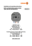
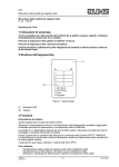
The light sensor consists of the following:
c: Base plate
d: Brightness sensor
e: LED
Abb. A
c
d e
2.
Activating the sensor/inserting the batteries
Battery type:
The light sensor is operated with a lithium button cell (type CR 2450N). The battery is included with
the sensor.
To avoid damaging the electronics through electrostatic discharge, you must comply with the safety
precautions for electrostatically sensitive devices when changing the battery.
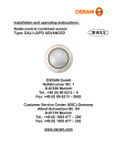
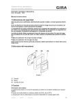
Inserting (replacing) the battery
Abb. B
1. Detach the light sensor from the base plate by
turning the unit approx. 45° anticlockwise (Fig. B).
2. If there is an old battery in the sensor:
Remove this battery. You need to wait about 2
minutes before inserting the new battery to allow
the capacitor to discharge.
45°
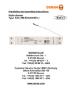
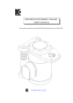
Abb. C
3. Insert the new battery as shown in Fig. C. The battery
should make contact with the side ⊕ contact of the battery
holder. Push the battery gently until it clicks in place. Make
sure the battery is the right way round (⊕ = on top = visible
when inserted). Make sure there is no grease on the battery.
4. When the battery is inserted, the light sensor spends
the first 30 seconds sending special programming telegrams
so that it can be identified in the system.
The LED will flash during this process.
Installation instructions: Light Sensor DALI LS ADVANCED
Page 3
Flat battery indicator:
The LED integrated in the light sensor (Fig. A 3) can only be seen in darkness. It flashes about three
times whenever a transmission is made.
If the LED flashes about ten times, this indicates that the battery is almost flat (LowBatt) and has to be
replaced.
Important:
Keep batteries away from children. If a battery is swallowed, seek medical attention immediately.
Replace the battery with one of the same type.
The old battery should be removed immediately and disposed of properly.
3.
Programming in the ADVANCED central unit
The light sensor must be trained for lighting control in the central unit so that the central unit can
identify the sensor as part of its system.
The actual function of the sensor is assigned to the central unit by the manual programming unit
(MPU) Î see also the operating instructions for the manual programming unit.
A light sensor can only be assigned to one group of the lighting control system.
A maximum of eight light sensors or combined sensors can be integrated in the system.
Procedure
1. Remove the battery from the light sensor (allow enough time for the capacitor to discharge).
2. On the manual programming unit (MPU), start the "radio startup" programming mode.
3. Insert the battery again. The light sensor will now transmit special programming telegrams for
approx. 30 seconds, to which the manual programming unit will react ("light sensor found"). On the
MPU, enter the number of the luminaire group to be controlled by this sensor.
4. Terminate the radio startup procedure on the MPU.
This completes the programming process.
Notes:
When you enter the group on the MPU the message "programming..." will appear. This message does
not disappear until the light sensor stops sending programming telegrams (up to 30 seconds after the
battery has been inserted). During this time, no other functions can be performed by the system.
We recommend that you label the light sensor with the device number indicated on the MPU and enter
this number in the documentation for the lighting system.
Deleting the sensor in the DALI ADVANCED central unit
Trained devices can be deleted via the MPU Î see the operating instructions for the manual
programming unit.
Page 4
Installation instructions: Light Sensor DALI LS ADVANCED
4.
Installation
Electrical equipment may only be installed by qualified electricians.
The light sensor is installed on the ceiling above an illuminated work area (Fig. D).
Make sure the sensor is not exposed to direct light.
Note
Do not attach the light sensor to the base plate until you have inserted the battery and trained the
sensor in the central unit.
Installation:
1.) Detach the light sensor from the base plate by turning the unit
approx. 45° anticlockwise.
Abb. D
1,7 m
2,5 m
2.) Install the base plate directly on the ceiling using the screw
provided (Fig. E1) or the adhesive pad.
3.) Turn the light sensor clockwise through no more than 45° on
the base plate until it clicks into place.
Abb. E
c
d
To improve radio transmission, you can thread the antenna out of the casing. To do this, puncture the
antenna opening (Fig. E2) carefully with a screwdriver and push the antenna through the hole before
installing the base plate. Do not strip the antenna or shorten it.
Installation instructions: Light Sensor DALI LS ADVANCED
Page 5
5.
Lighting control/setpoint adjustment
As already mentioned, a group is assigned to the light sensor when it is trained in the
ADVANCED central unit. The luminaires of this group will then be controlled by the sensor.
This group must also be assigned at least one channel button on a wall-mounted or hand-held
transmitter for operating the lighting controls. Train the relevant channel button using the
manual programming unit and then assign this button to the group to be controlled ("control of
group XX",Î see operating instructions for the manual programming unit).
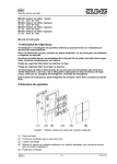
Setting the brightness setpoint
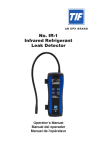
Abb. F
c
d
e
The luminance measured on the light sensor (Fig. F2)
comprises the reflected artificial light (Fig. F1) and
daylight (Fig. F3) and depends on the reflective
properties of the surface (Fig. F4).
It is transmitted as a brightness value at regular intervals
to the central unit for evaluation. If the setpoint is
changed, this brightness value is stored in the central
unit as the setpoint for lighting control.
f
Changing the setpoint:
Select "Regulation" in the "Lighting Control" menu on the manual programming unit. Enter the number
of the group to be controlled. You can now change the setpoint. Adjust the lighting to the required
setting and select "Change Setpoint". The message "waiting for brightness value.." will appear. The
next brightness value that the light sensor sends is stored as the new setpoint in the central unit
("Setpoint changed"). This process may take up to 90 seconds.
Activate lighting control by switching the "Regulation" option to "ON".
Note:
As long as there is a radio link between the MPU and the central unit, lighting regulation will
not be carried out.
Lighting control
Lighting control is active if the relevant group has been switched on because a trained channel button
on a wall-mounted or hand-held transmitter has been pressed (short press). The lighting system is
switched to 100 % and the brightness is then adjusted to the setpoint stored in the central unit. If the
measured brightness value exceeds the current brightness setpoint at the minimum dimmer setting for
the luminaires, the relevant group is automatically switched off. The lighting system is not
automatically switched on again.
Terminating control
If the regulated group is adjusted (faded up or down) using trained channel buttons on a wall-mounted
or hand-held transmitter, lighting control is terminated and the lighting value set manually is retained.
The same applies when a lighting scene involving the regulated group is selected. To restart lighting
control, you need to switch the group off and on again using an appropriate trained channel button.
Page 6
Installation instructions: Light Sensor DALI LS ADVANCED
6.
Notes on radio operation
A non-exclusive transmission path is used for radio transmission, which means that
interference cannot be ruled out.
Radio transmission is not suitable for safety applications, such as emergency shutdown or
calls to the emergency services.
The range of a transmitter (up to 100 m in the open) depends on the nature of the building:
Dry material
Wood, plaster, plasterboard
Brick, MDF
Reinforced concrete
Metal, metal grating, aluminium
cladding
Penetration
approx. 90 %
approx. 70 %
approx. 30 %
approx. 10 %
Notes on radio operation
This radio system may only be connected to other communication networks if this does not
infringe the relevant national laws.
-
This radio system may not be used for communicating beyond property boundaries.
-
If operated in Germany, the regulations contained in Official Bulletin Vfg 73/2000 must be met.
If used as specified, this device complies with the requirements of the R&TTE directive
(1999/5/EU). A complete conformity declaration can be found on the internet at: www.osram.com
The light sensor may be operated in all EU and EFTA states.
Installation instructions: Light Sensor DALI LS ADVANCED
Page 7
7.
Technical data
Power supply:
3 V DC
Battery:
1 x lithium cell CR 2450N
Transmission frequency: 433.42 MHz, ASK
Range:
max. 100 m (in the open)
Coding:
> 1 billion possibilities
Type of protection:
IP 20
Temperature range:
+5 °C to +55 °C
Relative humidity:
max. 65% (no condensation)
Brightness:
approx. 3 lx to 2000 lx
Dimensions (∅ x H):
52 mm x 23 mm
Date 13.09.02 / Light Sensor ADVANCED Version 1.0
Subject to change without notice. Errors and omission excepted.
Page 8
Installation instructions: Light Sensor DALI LS ADVANCED