1
3 Functional Description
3.4 Special functions of the error connection
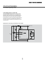
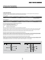
The fault output pin can be configured to act as an input
or an output. Use the appropriate command found in
the following table to configure the pin for the desired
functionality.
Fault pin as pulse output:
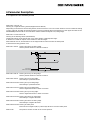
In the ENCOUT mode the fault pin is used as pulse
output, which outputs an adjustable number of pulses per
magnetic pitch. The pulses are derived from the Hall sensor
signals of the LM motors and are limited to 4000 pulses per
second.
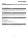
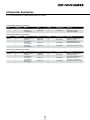
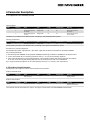
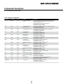
Command
Function
Description
ERROUT
Error Output
Fault pin as error output
ENCOUT
Encoder Output
Fault pin as pulse output
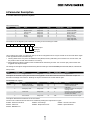
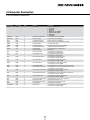
Command
Function
Description
DIGOUT
Digital Output
Fault pin as digital output.
The output initializes to low logic
(pulled to GND)
LPN
Load Pulse
Number
Preset pulse number for ENCOUT.
Value range: 1 to 255
DIRIN
Direction Input
Fault pin as direction input
REFIN
Reference Input
Fault pin as reference
or limit switch input
Example:
Output 100 pulses per magnetic pitch at the fault pin:
LPN100
In the case of 18 mm/s = 100 pulses per second are output.
The REFIN and DIRIN functions have already been
explained in the relevant sections.
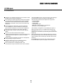
– One of the set current limitation values (LPC, LCC)
is exceeded
For speeds that would generate more than the maximum
possible pulse number at the set LPN value, the maximum
number is output. The set pulses are precisely achieved,
but the timing does not necessarily have to exactly agree
(delays possible). Position determination via pulse counting
is therefore possible, provided that no change occurs in the
direction and the maximum possible pulse number is not
exceeded.
– Set maximum permissible speed deviation (DEV)
is exceeded
Fault pin as digital output:
Fault pin as error output:
In ERROUT mode the output is set as soon as one of the
following errors occurs:
− Overvoltage detected
In DIGOUT mode, the error connection can be used as
universal digital output. The digital output can be set
or deleted via the following commands.
− Maximum coil or MOSFET temperature exceeded
In order to hide the transient occurrence of errors during
the acceleration phase, for example, an error delay can
be set which specifies how long an error must be present
before it is displayed at the error output:
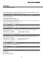
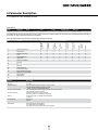
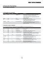
Command
Function
Description
DCE
Delayed Current
Error
Delayed error output for ERROUT
in 1/100 sec.
Example:
Only display error after 2 seconds: DCE200
If one of the above errors occurs, a corresponding
Emergency Object is sent to the CAN network!
Please consider the error mask in object 0x2320.
Only it is set at 1, the error status will be send.
See also chapter 6.2 Manufacturer-specific objects
under FAULHABER fault register.
21
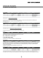
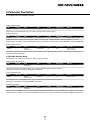
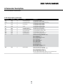
Command
Function
Description
CO
Clear Output
Set digital output DIGOUT
to low level
SO
Set Output
Set digital output DIGOUT
to high level
TO
Toggle Output
Switch digital output DIGOUT