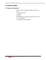
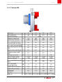
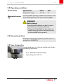
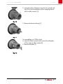
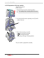
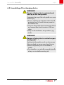
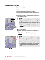
1
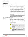
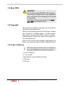
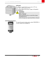
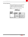
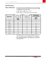
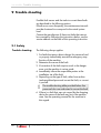
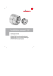
Installation manual Jaw module Jaw module. Table of contents 1 General...................................................................................................................4 1.1 Information about this manual........................................................................4 1.2 Explanation of symbols..................................................................................4 1.3 Limitations of liability.....................................................................................5 1.4 Max. RPM....................................................................................................6 1.5 Copyright.....................................................................................................6 1.6 Scope of delivery..........................................................................................6 1.7 Spare parts..................................................................................................7 1.8 Warranty terms............................................................................................7 2 Safety......................................................................................................................8 2.1 Responsibility of the customer.........................................................................8 2.2 Personnel requirements..................................................................................8 2.3 Intended use.................................................................................................9 2.4 Personal protective equipment......................................................................11 2.5 Special dangers..........................................................................................12 2.6 Further warnings.........................................................................................15 2.7 Clamping force...........................................................................................15 2.8 Screws.......................................................................................................16 2.9 Functionality...............................................................................................16 2.10 Environmental protection...........................................................................17 3 Technical data.......................................................................................................18 3.1 General information....................................................................................18 3.1.1 Variant RD......................................................................................19 3.1.2 Variant SE.......................................................................................20 3.2 Operating conditions..................................................................................21 3.3 Dimensional sheet.......................................................................................21 3.4 Type designation........................................................................................21 4 Structure and function.............................................................................................22 4.1 Overview RD*.............................................................................................22 4.2 Overview SE*.............................................................................................22 4.3 Brief description..........................................................................................23 4.4 Optional Accessories...................................................................................24 4.4.1 Jaws...............................................................................................24 4.4.2 Special grease.................................................................................25 5 Transporting, packaging, storing.............................................................................26 5.1 Safety instructions for transporting................................................................26 5.2 Symbols on the packaging...........................................................................26 5.3 Transport inspection....................................................................................26 5.4 Packaging..................................................................................................27 5.5 Storing.......................................................................................................28 2 Order Hotline +49 [0]7144. 907-333 Jaw module. english 6 Assembly...............................................................................................................29 6.1 Pre-consideration........................................................................................29 6.2 Preparation................................................................................................30 6.2.1 Preparation of the machine for assembly............................................30 6.2.2 Preparation of the jaw module..........................................................32 6.3 Assembling of the clamping device...............................................................33 6.3.1 Assembly of the jaw module.............................................................34 6.3.2 Assembly of the jaws........................................................................36 6.3.3 Boring the soft jaws..........................................................................38 6.4 Tests..........................................................................................................40 6.5 Control of the stroke position........................................................................41 6.6 Activities after production is concluded.........................................................41 7 Disassembly, subsequent storage, disposal...............................................................42 7.1 Safety........................................................................................................42 7.2 Disassembly of the jaw module....................................................................43 7.2.1 Disassembling the jaws....................................................................43 7.2.2 Disassembling the jaw module..........................................................44 7.3 Subsequent storage of the clamping device...................................................44 7.4 Disposal.....................................................................................................45 8 Maintenance..........................................................................................................46 8.1 General.....................................................................................................46 8.2 Cleaning....................................................................................................47 8.3 Preservation...............................................................................................48 8.4 Use of lubricant..........................................................................................49 8.5 Maintenance schedule.................................................................................50 8.6 Bolt torque.................................................................................................51 9 Trouble shooting....................................................................................................52 9.1 Safety........................................................................................................52 9.2 Trouble shooting table.................................................................................53 9.3 Start-up after corrected fault........................................................................54 10 Appendix............................................................................................................55 10.1 Service Hotline..........................................................................................55 10.2 Representatives.........................................................................................55 10.2.1 Germany......................................................................................56 10.2.2 Europe..........................................................................................57 10.2.3 America........................................................................................60 10.2.4 Asia.............................................................................................61 10.2.5 Australia.......................................................................................62 10.2.6 Africa...........................................................................................62 11 Index...................................................................................................................63 »Translation of original installation manual« Order Hotline +49 [0]7144. 907-333 3 Jaw module. General 1 General 1.1 Information about this manual This manual enables safe and efficient handling of the clamping device. The manual is a component of the clamping device and must be kept in the immediate vicinity of the clamping device where it is accessible for personnel at all times. Personnel must have carefully read and understood this manual prior to starting all tasks. The basic prerequisite for safe work is compliance with all the safety instructions and handling instructions in this manual. Illustrations in this manual are provided for a basic understanding and may deviate from the actual model of the clamping device. It is assumed that the reader is familiar with standard procedures, such as cleaning the mounting surfaces. 1.2 Explanation of symbols Safety instructions Safety instructions are indicated by symbols in this operating manual. The safety instructions are introduced by signal words that express the scope of the hazard. The safety instructions must be strictly adhered to, you must act prudently to prevent accidents, personal injury, and material damage. DANGER … indicates an imminent dangerous situation than can result in death or serious injury if it is not avoided. WARNING … indicates a possible dangerous situation that can result in death or serious injury if it is not avoided. 4 Order Hotline +49 [0]7144. 907-333 Jaw module. General english CAUTION … indicates a possible dangerous situation that can result in minor or light injury if it es not avoided. NOTE … indicates a possible dangerous situation that can result in material damage if it is not avoided. Tips and recommendations … indicates useful tips and recommendations, as well as information for efficient and trouble-free operation. 1.3 Limitations of liability All information and instructions in this operating manual have been provided under due consideration of applicable standards and regulations, the current state of technology, as well as our many years of experience. The manufacturer assumes no liability for damage due to: ➢Failure to follow the instructions in the manual ➢Non-intended use ➢Deployment of untrained personnel ➢Unauthorized conversions ➢Technical changes ➢Use of non-approved spare parts The actual scope of delivery can vary from the explanations and graphic representations provided in this manual in the case of special versions, if supplemental order options are desired, or on the basis of the latest technical changes. The agreed obligations in the delivery contract, the general terms and conditions, as well as delivery conditions of the manufacturer, and the statutory regulations valid at the time the contract was concluded, apply. Order Hotline +49 [0]7144. 907-333 5 Jaw module. General 1.4 Max. RPM CAUTION! The maximum permissible RPM of the clamping device must be redetermined in every application case, on the basis of the clamping forces required for machining. Of all RPMs of the groups specified, the lowest given RPM must always be used. 1.5 Copyright This manual is protected by copyright and is provided exclusively for internal purposes. Delivery of the operating manual to third parties, duplication in any form – including excerpts – as well as exploitation and/or communication of the content, are not permitted [except for internal use] without written approval from the manufacturer. Actions to the contrary make damage compensation mandatory. We reserve the right to enforce additional claims. 1.6 Scope of delivery All tools and accessories that are not included in the scope of delivery are marked as optional. In scope of delivery: 1 Jaw module Optionally the scope of delivery includes: Claw jaws Soft jaws 6 Order Hotline +49 [0]7144. 907-333 Jaw module. General english 1.7 Spare parts WARNING! Safety risk if the wrong spare parts are used! Incorrect or defective spare parts can cause damage, malfunction, or total failure; they can also impair safety. Only use manufacturer's original spare parts. Only purchase spare parts from authorized dealers or direct from the manufacturer. Addresses are in the appendix. 1.8 Warranty terms The warranty terms are included in the manufacturer's terms and conditions. Order Hotline +49 [0]7144. 907-333 7 Jaw module. Safety 2 Safety This section provides an overview o fall the important safety aspects for optimal protection of personnel, as well as for safe and trouble-free operation. 2.1 Responsibility of the customer The device is used in industrial applications. Consequently the owner of the device is subject to legal industrial safety obligations. In addition to the safety instruction in this manual, generally valid safety and accident protection guidelines, and environmental protection guidelines must be adhered to and complied with for the area of implementation of the device. WARNING! Risk of injury! Declining operating force, for example by declining energy supply, may cause serious personal injury. The product may be used only on machines where it is ensured, that during use, the operating force does not drop. 2.2 Personnel requirements WARNING! Danger of injury due to insufficient qualification! Improper handling of the clamping device can cause serious injury or material damage. Only have activities performed by personnel who are qualified to perform these activities. The following qualifications are cited in the operating manual for the various activity areas. 8 Order Hotline +49 [0]7144. 907-333 Jaw module. Safety english Specialized personnel are personnel who due to their specialized training, skills, and experience, as well as knowledge of the applicable regulations, are capable of executing the tasks assigned to them and of recognizing and avoiding possible hazards on their own. Hydraulic specialist The hydraulic specialist has been trained for the particular task area in which he is active and is familiar with the relevant standards and regulations. Due to his specialized training and experience the hydraulic specialist can perform tasks on hydraulic equipment and recognize and avoid possible dangers on his own. Electric specialist The electric specialist has been trained for the particular task area in which he is active and is familiar with the relevant standards and regulations. Due to his specialized training and experience the electric specialist can perform tasks on electric equipment and recognize and avoid possible dangers on his own. Only persons from whom it can be expected that they reliably execute their work are considered as personnel. Persons whose capability to react is impaired, for instance through drugs, alcohol, or medication, are not approved. Comply with age-specific and job-specific regulations that are applicable at the installation site when selecting personnel. 2.3 Intended use The clamping device is designed for installation in a machine tool according to CE compliant. Within the machine tool the clamping device is designed exclusively as a through-bore chuck for bar work and / or as an endstop chuck for chuck work. The clamping device should only be mounted, operated, maintained, and cleaned by instructed, specialized personnel. Order Hotline +49 [0]7144. 907-333 9 Jaw module. Safety Intended use also includes compliance with all the instructions in this manual. The clamping device is to be used for the case of application contractually agreed between the producer/deliverer and the user, as well as such cases of application described in the product description which are also in accordance with the technical values. The safe function of the clamping device is, as far as it can be foreseen, guaranteed when it is used for the intended purpose in accordance with the appropriate safety regulations. Any use that extends beyond the intended use, or any other use of the clamping device is considered to be misuse and can cause dangerous situations. WARNING! Danger due to misuse! Misuse of the clamping device can cause dangerous situations. Particularly refrain from the following uses of the clamping device: Use in machines other than machine tools. Use in machine tools with technical data other than that specified on the clamping device. Claims of any type due to damage arising from non-intended use are excluded. Unintended and improper use of the Power Chuck is for example If workpieces are not clamped properly If safety regulations are disregarded and persons are working at the clamping device without additional protective devices e.g. for machining. If the clamping device is used for machines or tools for which it is not intended. 10 Order Hotline +49 [0]7144. 907-333 Jaw module. Safety english 2.4 Personal protective equipment Wearing of personal protective equipment is required to minimize health hazards when working with the device. Always wear the protective equipment necessary for the respective task when working with the device. Follow the instructions that have been posted in the work area. Always wear For all tasks always wear: Protective work clothing is tight-fitting work clothing with low resistance to tearing, with tight sleeves, and without projecting parts. It is primarily used to protect against entanglement by moving machine parts. Do not wear rings, chains, or other jewelry. Safety footwear for protection against heavy falling parts and slipping on slippery substrates. For special tasks wear Special protective equipment is required when executing special tasks. Separate reference is made to this equipment in the specific sections of this manual. This special protective equipment is explained below: Hard hat to protect against falling and flying parts and materials. Protective goggles to protect eyes from flying parts and liquid splashes. Protective gloves to protect hands from friction, abrasion, puncture wounds, or deeper injuries, as well as from contact with hot surfaces. Order Hotline +49 [0]7144. 907-333 11 Jaw module. Safety 2.5 Special dangers In the following section residual risks are cited that occur due to installation of the clamping device in a machine tool. In each case the residual risks that have been determined based on a risk analysis of the machine must be specified by the customer. Horizontal / lying parts Follow the safety instructions listed here and the warnings in the other sections of this manual to reduce health hazards and to avoid dangerous situations. WARNING! Danger of injury due to horizontal parts! Before transporting the clamping device in horizontal condition: Put the clamping device on a non-slip pad Screw in the eye bolts Suspended loads WARNING! Life-threatening danger due to suspended loads! Some clamping devices must be lifted with a crane. When lifting the clamping device there is a life-threatening hazard due to falling parts or parts swinging out of control. Never step under suspended loads. Comply with the instructions concerning the intended attachment points. Ensure that the sling gear is securely seated! Do not attach lifting gear in projecting components. Only use approved hoists and sling gear with sufficient bearing capacity. Do not use rope and belts that are torn or frayed. 12 Order Hotline +49 [0]7144. 907-333 Jaw module. Safety Moving parts english WARNING! Danger of injury due to moving parts! Rotating parts of the clamping device can cause serious injuries. Do not reach into moving parts or handle moving parts during operation. Note the gap dimensions of moving parts. Do not open covers when the device is in operation. Be aware of afterrun time: Prior to opening the covers ensure that all parts have come to a standstill. Wear tight-fitting protective work clothing in the danger zone. Wrong clamping of the work piece WARNING! Danger of injury due to incorrect clamping of the work piece! Incorrect work piece clamping may lead to the ejection of the work piece and result in serious injuries. Under dimensioned (tolerance) parts can lead to incorrect clamping! Check the unmachined work pieces at random on dimensional accuracy. Too low supply pressure can lead to the reduction of clamping force! Too high supply pressure can lead to damage of the components of the clamping device! Check and adjust, if necessary, the supply pressure regularly. Do random checks of the unmachined work pieces on dimensional accuracy. Order Hotline +49 [0]7144. 907-333 13 Jaw module. Safety Missing changing parts WARNING! Danger of injury due to missing changing parts! When operating the clamping device without changing parts [segmented clamping bushing, clamping heads, work piece end-stops] there is a higher danger of crushing injuries due to the stroke of movable components of the clamping device. The clamping process may not be initiated without assembled segmented clamping bushing and/or work piece end-stop. Parts with sharp edges WARNING! Risk of injury! When screwing in individual components such as for example work piece end-stops, threaded adapters and similar devices that are equipped with an external thread or wear caused by burrs, there is risk of cutting. The operation must be done only by qualified personnel. Wearing of gloves / [PSA] is required! 14 Order Hotline +49 [0]7144. 907-333 Jaw module. Safety english 2.6 Further warnings WARNING! Risk of injury! Never reach for the clamping device while the spindle is rotating. Before starting to work on the mandrel, make sure the machine spindle cannot be put in motion. WARNING! Risk of injury! By repeated reworking or wear and tear of the clamping surfaces sharp edges and burrs may appear and lead to severe cutting damages. WARNING! Damage of clamping device! The clamping device may be released exclusively in the standing condition! 2.7 Clamping force The achieved clamping force can vary due to the maintenance condition of the clamping device [state of lubrication and degree of contamination] [see chapter »Maintenance«]. The clamping force must be checked at regular intervals. This requires the use of static clamping force measuring devices. CAUTION! Damages due to excessive draw and compressive force! An excessive draw force and/or compressive force may damage the clamping device. The max. draw force and compressive force may not be exceeded. Order Hotline +49 [0]7144. 907-333 15 Jaw module. Safety 2.8 Screws Moving parts WARNING! Danger of injury due to screws and stud screws being accelerated out of the device!! Screws and stud screws radially attached to the product can be accelerated out of the device and cause severe injuries. At the product radially mounted screws and stud screws which were loosened for assembly and maintenance must be re-tightened with the correct tightening torque! The tightening torque is given at the product itself, near the screw or threaded pin, and/or given in chapter »Bolt torque«. All screws or stud screws that are not marked with a tightening torque specification are tightened with the prescribed tightening torque and locked [medium-strength bonding] in the factory and should only be unscrewed after consultation with the manufacturer. If in doubt you must contact the manufacturer immediately do determine the subsequent procedure. 2.9 Functionality NOTICE! With high contamination of the clamping device the functionality is no longer guaranteed. The cleaning and maintenance intervals must be observed. 16 Order Hotline +49 [0]7144. 907-333 Jaw module. Safety english 2.10 Environmental protection NOTE! Environmental hazard due to incorrect handling! Incorrect handling of environmentally hazardous substances, particularly improper disposal, can cause significant environmental damage. Always comply with the instructions cited below If environmentally harmful substances should inadvertently get into the environment, initiate suitable measures immediately. If in doubt notify the responsible municipal authority about the damage. The following environmentally harmful substances are used: Lubricants Lubricants like greases and oils can contain toxic substances. Ensure that they do not get into the environment. The device must be disposed of by a specialized disposal company. To achieve trouble-free operational performance of the clamping device only use HAINBUCH lubricants. See the appendix for reference addresses. Order Hotline +49 [0]7144. 907-333 17 Jaw module. Technical data 3 Technical data 3.1 General information The jaw module is available in different sizes and variants. Information about e.g. dimensions weight you will find on the corresponding drawing that you can order at HAINBUCH. For examples some technical data: 18 Order Hotline +49 [0]7144. 907-333 Jaw module. Technical data english 3.1.1 Variant RD Fig. 1 Chuck size Jaw module size Concentricity [mm] Clamping range [mm] Speed n max. [1/min] max. actuating force at unscrewing the jaws [KN] max. draw force axial [KN] max. clamping force radial [KN] Release stroke radial [mm] Clamping reserve radial [mm] Stroke per jaw [mm] Variant of gear cutting Vibration circle-Ø max. permissible boring-Ø [mm] max. permissible boring depth [mm] Length without jaws [mm] Length with jaws [mm] Weight [kg] On stock Order no. 65 145 65 215 80 215 100 215 0,020 A 115 5000 183 3000 183 3000 186 3000 29 29 29 29 29 29 29 29 60 60 60 60 C 0,9 0,9 0,9 1,8 D 0,7 0,7 0,7 1 AT AX 1,6 1,5x60° ~149 1,6 1,5x60° ~220 1,6 1,5x60° ~220 2,8 1,5x60° ~220 BW 115 200 200 200 BX 15 15 15 15 AI AJ 37,5 77 6,3 ü 37,5 77 11,3 ü 37,5 77 12,6 ü 37,5 77 14,5 ü 10721/0001 10721/0002 10721/0003 10721/0004 Order Hotline +49 [0]7144. 907-333 19 Jaw module. Technical data 3.1.2 Variant SE Fig. 2 Chuck size Jaw module size Concentricity [mm] Clamping range [mm] Speed n max. [1/min] max. actuating force at unscrewing the jaws [KN] max. draw force axial [KN] max. clamping force radial [KN] Release stroke radial [mm] Clamping reserve radial [mm] Stroke per jaw [mm] Variant of gear cutting Vibration circle-Ø max. permissible boring-Ø [mm] max. permissible boring depth [mm] Length without jaws [mm] Length with jaws [mm] Weight [kg] On stock Order no. 20 65 145 0,020 115 5000 65 215 0,020 183 3000 100 215 0,020 186 3000 29 29 29 AX BW 29 60 0,9 0,7 1,6 1,5x60° ~149 115 29 60 0,9 0,7 1,6 1,5x60° ~220 200 29 60 1,8 1 2,8 1,5x60° ~220 200 BX 15 15 15 AI AJ 37,5 77 6,3 ü 37,5 77 11,3 ü 37,5 77 14,5 ü 10720/0001 10720/0002 10720/0003 A C D AT Order Hotline +49 [0]7144. 907-333 Jaw module. Technical data english 3.2 Operating conditions Environment Mechanical actuating Specification Value Unit Temperature range 15 - 65 °C In each possible operating condition the maximum draw force and compressive force may not be exceeded! WARNING! Risk of injury! Using false technical data can lead to serious personal injury and property damage. The technical data [label on the product, assembly drawing] must be observed and may not be modified by the operator! 3.3 Dimensional sheet Dimension sheets for the respective product can be requested from HAINBUCH. 3.4 Type designation The type designation is on the jaw module and includes the following information: 1 2 ID no. [marked with the # symbol] Type designation and size Fig. 3 Order Hotline +49 [0]7144. 907-333 21 Jaw module. Structure and function 4 Structure and function 4.1 Overview RD* 1. x 1. Adjustable top jaw with serration 2. Base body 3. Locking screw 4. Coupling 5. CENTREX system for mm-precise insertion without aligning 6. Base jaw 7. Slot nut Fig. 4 4.2 Overview SE* 1. Adjustable top jaw with serration 2. Base body 3. Locking screw 4. Coupling 5. CENTREX system for mm-precise insertion without aligning 6. Base jaw 7. Slot nut Fig. 5 * View as an example 22 Order Hotline +49 [0]7144. 907-333 Jaw module. Structure and function english 4.3 Brief description Small workpiece – small chuck This is the simple formula of our new modular solution. Using the new small jaw module, about 80 % of usual components are covered, and for larger components it can be easily changed over to a large jaw module within 30 seconds. The basic unit is a SPANNTOP chuck or TOPlus chuck. So add to this the jaw modules, clamping heads and mandrels; you achieve reliability, accuracy, and safety that traditional jaw chucks lack especially for I.D. clamping. Clamp from inside with a jaw chuck – at any rate this is hardly done by anyone. Those who have experience with HAINBUCH mandrels are aware of the unbelievable, even seeming almost impossible clamping situations that are feasible. The new jaw module now completes a clamping system that offers the right solution for each clamping situation, without compromise. Key advantages Minimal interference contour, optimal utilization of the jaws Flexible, fast and repeatable change-over to clamping head or mandrel clamping Deadlength clamping with jaws [e.g. claw jaw clamping on the blank] Rigid workpiece clamping with pull-back effect through the use of clamping head or mandrel [e.g. short clamping for machining finished parts] Full passage with actuation of the clamping head Ideal for sensitive clamping and delicate components Can be used as a pick-up chuck on sub spindles Also excellently suited for stationary use Order Hotline +49 [0]7144. 907-333 23 Jaw module. Structure and function CAUTION! Risk of injury! Risk of component fracture when using the jaw module for I.D. clamping. Use the jaw module only for O.D. clamping! 4.4 Optional Accessories The accessories described here are not included in the scope of delivery. Specially developed segmented clamping bushings match to the respective maximum RPM are available for each clamping device. Trouble-free and precise function of HAINBUCH clamping devices is only ensured when using original HAINBUCH segmented clamping bushings. Lubricating grease and grease gun are required for cleaning and preservation of the clamping device. The lubricating grease is also specially matched for protection of the vulcanized segments of the segmented clamping bushings and increase their service life and elasticity by a significant factor. 4.4.1 Jaws The jaw module can be used with a claw jaw set or with soft jaws. Claw jaw set counter bore Side 1: 25 – 34 – 43 - 52 mm Side 2: 61 – 70 mm 10723/0001 79 – 88 mm 10723/0002 97 – 106 mm 10723/0003 Fig. 6 24 Order no. Order Hotline +49 [0]7144. 907-333 Jaw module. Structure and function english Soft jaws The soft jaws can be bored up to a max. ø115 mm [size 145] or ø200 mm [size 215]. They can be ordered with order number 10724/0001 from HAINBUCH. CAUTION! Fig. 7 Risk of injury! When boring the soft jaws remind the chapter »Boring the jaws«! Risk of component rupture by failure to observe! 4.4.2 Special grease The special grease has the order number 2085/0005; it can be ordered from HAINBUCH. Fig. 8 Order Hotline +49 [0]7144. 907-333 25 Jaw module. Transporting, packaging, storing 5 Transporting, packaging, storing 5.1 Safety instructions for transporting Unbalanced package WARNING! Danger of falling due to an unbalanced package Packed goods can have an unbalanced package. If attached incorrectly the package can tip and cause life-threatening injuries. Note the markings on the packages. Attach the crane hook in such a manner that it is located above the center of gravity. Carefully lift and see if the load tilts. If necessary change the attachment. 5.2 Symbols on the packaging Fragile Identifies packages with fragile or sensitive contents. Handle the packed goods with care; do not allow them to fall, and do not subject them to impact. Protect from moisture Keep packed goods dry and protected against moisture. 5.3 Transport inspection Check delivery immediately upon receipt to ensure that delivery is complete and to identify any transport damage. Proceed as follows it there is apparent external damage: Do not accept the delivery, or only accept it with reservation. Note the extend of transport damage on the transport documents or on the transport company's delivery ticket. Submit a complaint. 26 Order Hotline +49 [0]7144. 907-333 Jaw module. Transporting, packaging, storing english Report any defect as soon as it is detected. Claims for damage compensation can only be enforced during the applicable periods for giving notice of lack of conformity. 5.4 Packaging About the packaging Individual packages are packed according to the expected transport conditions. Environmentally-friendly materials have been used exclusively for the packaging. Packaging should protect the specific components from transport damage, corrosion, and other damage until installation. Therefore do not destroy the packaging, remove it just before installation. The packed goods are sealed in foil airtight and packed in cartons. See the »Technical Data« section for the specific weight of the respective sizes. Handling packaging materials Dispose of packaging materials in accordance with the respectively valid statutory regulations and local guidelines. NOTE! Improper disposal causes environmental damage! Packaging materials are valuable raw materials and in many cases they can be reused, or they can be effectively treated and recycled. Dispose of packaging materials in an environmentally responsible manner. Comply with locally applicable disposal guidelines. If necessary commission a specialized company to dispose of packaging. Order Hotline +49 [0]7144. 907-333 27 Jaw module. Transporting, packaging, storing 5.5 Storing Under certain circumstances instructions for storage and subsequent storage are affixed to the packages that extend beyond the requirements cited here. Comply with these instructions accordingly. Storage of packages Only store packages under the following conditions: Do not store outdoors. Store in a dry and dust-free location Do not expose to aggressive media Protect from direct sunlight Avoid mechanical vibration Storage temperature: 15 bis 35 °C Relative humidity: max. 60 % For storage periods longer than 3 months: Check the general condition of all parts and the packaging at regular intervals. Touch up or re-apply anti-corrosion agents as needed Subsequent storage Only re-store the clamping device under the following conditions: of the clamping device Thoroughly clean the clamping device prior to subsequent storage [see section »Cleaning«] Thoroughly oil and grease the clamping device. [see section »Cleaning«] Store the clamping device in airtight foil The clamping device must be stored securely in position. If this is not guaranteed, use a suitable container for the clamping device or equip the shelf with a circumferential securing edge. 28 Order Hotline +49 [0]7144. 907-333 Jaw module. Assembly english 6 Assembly 6.1 Pre-consideration Screws are tightened according to the size of the screw and the general torque. To avoid axis-parallel warpage under load and to get stiffness turn in the screws evenly. To avoid precision error clean the screw joint surfaces and also the mating surfaces, see »Maintenance«. The ex works wetting of the plate surfaces and the clamping element is only corrosion protection. It's not functionally lubricated. The insertion of lubricant is provided only on the mechanical surfaces. Pay attention to the instructions for lubricants in the chapter »Maintenance«. Avoid too much lubricant on the bearing surface, as this can cause face runout. Seal rings (e.g. o-ring, quad-ring seal) and sealing surfaces must be lubricated. Note the information in the chapter »Maintenance«. Note that the function surfaces (plate surface, mating surface, cone surface and seal surface) may not be damaged. CAUTION! Wear safety shoes during the assembly and maintenance work. Make sure that the starting of the spindle is impossible. Order Hotline +49 [0]7144. 907-333 29 Jaw module. Assembly 6.2 Preparation The total weight of the jaw module depends on the size and can be as much as 15 kg. NOTE! Material damage due to falling of the jaw module! When mounting the jaw module can fall and be damaged e.g. may cause material damage at the machine. Two people are always required for this task. Always handle carefully with the jaw module Always wear safety footwear. 6.2.1 Preparation of the machine for assembly Before assembling the jaw module to the base end-stop of the clamping device must be disassembled. 8. x Special tools required: Allen wrench Changing fixture 1. Remove the assembled clamping head [1] with a suitable changing fixture [2]. Fig. 9 30 Order Hotline +49 [0]7144. 907-333 Jaw module. Assembly english 2. Loosen the three clamping screws for the ground endstop [2] in the circumference of the clamping device with an allen wrench [1]. Fig. 10 3. Remove the base end-stop [1]. Fig. 11 For assembling to a TOPlus chuck: 4. Loosen the three countersunk screws [3] at the plate [1] by using an allen wrench [2]. 5. Remove the plate [1]. Fig. 12 Order Hotline +49 [0]7144. 907-333 31 Jaw module. Assembly 6.2.2 Preparation of the jaw module 6. x Special tools required: Allen wrench 1. Move the base jaws [1] in outermost position. 1 The coupling slider is thereby pulled to the front. Fig. 13 2. Turn back [out] the centric operating screw [2] until it is about 3mm out. 2 Fig. 14 3. Remove the mounting screws [3]: either the mounting screws M6 or the mounting screws M8 depending on the type of clamping device. 3 Fig. 15 The jaw module is prepared for assembly. 32 Order Hotline +49 [0]7144. 907-333 Jaw module. Assembly english 6.3 Assembling of the clamping device WARNING! Danger of injury due to unintentional start-up of the tool spindle! Unexpected start-up of the tool spindle can cause severe injury. Prior to switching on automatic mode close all protective doors or hoods that are present on the machine tool. Unscrew all eye bolts from the clamping device and remove them from the interior of the machine. Only run the machine in set-up mode or jog mode. WARNING! Danger of injury due to vertical suspended spindle! Bending into the machine work are when assembling overhead can cause severe head injuries. Secure components prior to overhead assembly. For assembly on a vertically suspended spindle always use a suitable mounting aid. Order Hotline +49 [0]7144. 907-333 33 Jaw module. Assembly 6.3.1 Assembly of the jaw module 4. x WARNING! Danger of injury due to vertical suspended spindle! Bending into the machine work are when assembling overhead can cause severe head injuries. Secure components prior to overhead assembly. For assembly on a vertically suspended spindle always use a suitable mounting aid. Special tools required: Allen wrench SW5 / SW6 1. Put the machine into set-up mode. 2. Remove all tools from the machine's interior. 3. Reduce the clamping pressure of the machine to lowest level. 4. Move the drawtube of the machine into front end position [release position]. Note the position of the torsional safety! 5. Place the jaw module on the chuck. Fig. 16 6. Screw in the 3 mounting screws - 3xM6 at SPANNTOP nova / TOPlus and/or. - 3xM8 at SPANNTOP mini / TOPlus mini and tighten them firmly with the correct tightening torque, see chapter »Maintenance«. Fig. 17 34 Order Hotline +49 [0]7144. 907-333 Jaw module. Assembly english 7. Screw in the central screw till end. WARNING! Fig. 18 The central screw now must be flush to the front side be about 1 mm deeper than the cover sheet Please refer to chapter »6.5 Control of the stroke position« 8. The coupling jaws are now operated and engage to the chuck coupling. The jaw module is coupled. CAUTION! Risk of injury! When assembled incorrect, the clamping force may not be sufficiently transferred. Too low clamping force can lead to the ejection of the workpiece. Make sure that the central screw is mounted correctly. Move the machine into release position! State of release position: State of release position: WRONG assembled CORRECT assembled Fig. 19 Central screw protrudes Fig. 20 Central screw deepened about 1mm The jaw module is assembled. Order Hotline +49 [0]7144. 907-333 35 Jaw module. Assembly 6.3.2 Assembly of the jaws 9. x Special tools required: Allen wrench SW10 1. Put the machine into set-up mode. 2. Remove all tools from the machine's interior. 3. Reduce the clamping pressure of the machine to lowest level. 4. Move the drawtube of the machine into front end position [release position]. 3 NOTE! Material damage due to incorrect tightening torque! By incorrect tightening torque components can be damaged. Notice the permissible [maximum] torque of 100 Nm! Fig. 21 5. Assemble the top jaws Put on the top jaws. Position the jaws by the marking and the scale on the cover plate. Tighten the screws [3] with the tightening torque of 100 Nm . NOTE! Material damage caused by exceeding the maximum position! By exceeding the maximum position, the strength of the component is no longer ensured. In greatest position the slot nut must maximum be flush with the outer diameter of the base jaws! Fig. 22 36 Order Hotline +49 [0]7144. 907-333 Jaw module. Assembly english When inserting the claw jaws and pushing into the smallest position the specified clamping diameter is achieved. Example: Jaw module size145 clamping-Ø 79 Screw the claw jaws onto the slot nut without tightening, so the claw jaw is still movable Push the claw jaws completely inside to the endstop Pull back until they engage to the next possible gearing Tighten the claw jaws. The clamping diameter of 79 mm is reached. When clamping beginning at Ø 82 the claw jaw can be set by 1 tooth to the outside. The clamping range is increased by 3 mm. Order Hotline +49 [0]7144. 907-333 37 Jaw module. Assembly 6.3.3 Boring the soft jaws 6. x Special tools required: Allen wrench SW10 NOTE! Material damage due to component fragmentation! Incorrect boring of the soft jaw can cause component failure. Observe the max. boring contour, see figure below! Fig. 23 Always assemble the soft jaws in suitable position for workpiece clamping. By positioning the jaws in the smallest possible area the centrifugal loss is minimized. 1. Put the machine into set-up mode. 2. Remove all tools from the machine's interior. 3. Reduce the clamping pressure of the machine to lowest level. 4. Move the drawtube of the machine into front end position. 5. Adjust the clamping force to the level in which the workpiece will be clamped to achieve the best possible concentricity. Pay attention to the maximum allowed clamping force! 38 Order Hotline +49 [0]7144. 907-333 Jaw module. Assembly english NOTE! Material damage due to component fragmentation! Fig. 24 Component fragmentation due to wrong boring of the big diameters. When boring the big diameters from ø190 to ø 200 mm for size 215 from ø105 to ø 115 mm for size 145 the jaws must be assembled with the wide side facing out! 6. Set the jaws in their future clamping position by inserting a round material in the center of the jaws. The clamping position is reached when the base jaws are flush with the outside of the circumference. A reserve clamping stroke is ensured. 7. Bore the jaws in the usual way. Fig. 25 NOTE! Material damage due to lack of precision! Clamping jaws for highest repeatability must be bored and/or grinded out in the clamping device under clamping pressure. When boring and/or grinding out make sure, that the loading ring or loading plug is clamped by the top jaws and not from the base jaws. 8. Check the position of the base jaws and the reserve stroke by a test clamping. Order Hotline +49 [0]7144. 907-333 39 Jaw module. Assembly 6.4 Tests NOTE! Material damage due to damaged adaptation clamping device! A damaged, incomplete, or unbalanced adaption clamping device can significantly damage or even destroy the machine tool and the work piece. Only use complete and properly assembled adaptation clamping devices. If in doubt contact the manufacturer. Ensure the following points prior to each installation and start-up of the adaption clamping device: 40 The adaption clamping device must be undamaged. All cylindrical screws of the adaptation clamping device must be present and tightened with the proper tightening torque. The set RPM of the machine tool should not exceed the maximum permissible speed of the adaption clamping device; see chapter »Max. RPM«. The maximum drawtube force specified on the perimeter of the adaptation clamping device must not be exceeded. The clamping pressure of the machine is sufficiently high to clamp the workpiece securely. Of all the specified draw forces and pressure forces the lowest values are always to be used. All assembly tools must be removed from the interior of the machine. Adaptation clamping device and work piece must be compatible – check the clamping diameter regularly. The workpiece is clamped by a sufficient workpiece clamping in the adaptation clamping device. Order Hotline +49 [0]7144. 907-333 Jaw module. Assembly english 6.5 Control of the stroke position WARNING! Crushing danger from moving parts! Crushing danger from moving parts during controlling the stroke position! Gaps, caused while controlling the stroke position, can cause severe injury. Only do the controlling of the stroke position with assembled changing parts. Only run the machine in set-up mode or jog mode. Release position Fig. 26 Clamping reserve Clamping position Fig. 27 Fig. 28 6.6 Activities after production is concluded 9. x 1. Move the clamping device into unclamped position. 2. Switch off the machine tool and safeguard it from being switched on again. 3. Open the protective door or hood. 4. Clean the clamping device and a possibly mounted adaptation clamping device and adapter of chips and production residues using a soft, lint-free cloth and oil them lightly. 5. Close the protective door or hood. Order Hotline +49 [0]7144. 907-333 41 Jaw module. Disassembly, subsequent storage, disposal 7 Disassembly, subsequent storage, disposal If there is break in production that lasts longer than 3 days, the clamping device must be disassembled and properly stored in accordance with the manufacturer's specifications [see section »Transport, packaging, storage«]. Prior to disassembling: Put the machine in set up mode. Remove fuels and auxiliary materials, as well as residual processing materials and dispose of these items in an environmentally-responsible manner. 7.1 Safety Safeguarding against restart DANGER! Life-threatening danger if restarted without authorization When disassembling there is danger of the energy supply being switched on inadvertently. This poses a life-threatening hazard for persons in the danger zone. Prior to starting the tasks switch off all energy supplies and safeguard them from being switched on again. WARNING! Danger of injury due to falling components! When mounting components can fall and cause severe injury and material damage. Two people are always required for this task. Use a crane. For assembly on a vertically suspended spindle always use a suitable mounting aid. 42 Order Hotline +49 [0]7144. 907-333 Jaw module. Disassembly, subsequent storage, disposal english 7.2 Disassembly of the jaw module WARNING! Danger of injury due to vertical suspended spindle! Bending into the machine work are when assembling overhead can cause severe head injuries. Secure components prior to overhead assembly. For assembly on a vertically suspended spindle always use a suitable mounting aid. 7.2.1 Disassembling the jaws 6. x Special tools required: Allen wrench SW10 1. Put the machine tool in set up mode. 2. Remove all tool from the interior of the machine. 3. Set the clamping pressure of the machine on the lowest setting. 4. Move the drawtube of the machine into the front stop position [release position]. 5. Loosen and remove the screws [3]. 3 6. Remove the top jaws. Fig. 29 The jaws are disassembled. Order Hotline +49 [0]7144. 907-333 43 Jaw module. Disassembly, subsequent storage, disposal 7.2.2 Disassembling the jaw module 7. x WARNING! Danger of injury due to vertical suspended spindle! Bending into the machine work are when assembling overhead can cause severe head injuries. Secure components prior to overhead assembly. For disassembly from a vertically suspended spindle always use a suitable mounting aid. Special tools required: Allen wrench SW5 / SW6 1. Put the machine tool in set up mode. 2. Set the clamping pressure of the machine on the lowest setting. Fig. 30 3. Move the drawtube of the machine into the front stop position [release position]. 4. First turn back the central screw. The coupling jaws are actuated and release the coupling of the chuck. The jaw module is uncoupled. 5. Loosen and remove the 3 mounting screws. Fig. 31 6. Remove the jaw module from the clamping device. Fig. 32 The jaw module is disassembled. 7.3 Subsequent storage of the clamping device The clamping device must be cleaned and treated with corrosion protection for subsequent storage [see section »Cleaning«]. 44 Order Hotline +49 [0]7144. 907-333 Jaw module. Disassembly, subsequent storage, disposal english NOTE! The storage conditions are specified in the section »Transport, packaging and storage«. 7.4 Disposal If a return or disposal agreement has not been concluded, then recycle disassembled components. CAUTION! Risk of injury due to leaking fluids! Hydraulically or pneumatically operated clamping devices may contain residues of liquids. Uncontrolled leakage of fluids can lead to severe injuries. Open the pressure relief screw and drain remaining liquid. Discard the liquid. NOTE! Improper disposal causes environmental damage! Lubricants and other auxiliary materials are subject to treatment as special waste, and should only be disposed of by approved specialist companies! NOTE! Composite materials! For disposal clamping devices which include composite materials [mineral cast, CFK] must be returned at HAINBUCH! Local municipal authorities or specialized disposal companies provide information on environmentally-responsible disposal. Order Hotline +49 [0]7144. 907-333 45 Jaw module. Maintenance 8 Maintenance Environmental pro- Comply with the following instructions for environmental protection when performing maintenance work: tection At all lubricating points where lubricant is applied by hand, remove escaping, used, or excess grease, and dispose of it in accordance with applicable local regulations. Collect used oil in suitable containers and dispose of it in accordance with applicable local regulations. 8.1 General Cleanliness of the appropriate end-stop as well as the guidance diameters are conditions for reaching the concentricity and perpendicularity tolerances. Clean these surfaces with an appropriate cleaner. CAUTION Danger of injury due to improper handling of cleaners! Improper handling of cleaners can cause health impairments. Always comply with the safety data sheets and guidelines provided by the manufacturer of the cleaning agent for handling/using the cleaners. CAUTION Danger of injury due to loss of clamping force! Fouling of the clamping device can cause the clamping device to lose considerable clamping force. Always comply with the maintenance and cleaning intervals specified in this manual. In conjunction with the maintenance intervals, regularly check the maintenance status of the clamping device through clamping force measurements. 46 Order Hotline +49 [0]7144. 907-333 Jaw module. Maintenance english NOTE! Material damage due to use of the wrong cleaning agent/cleaner! Seals and clamping elements can be damaged due to use of the wrong seals and clamping elements. Do not use any solvents that contain ester or polar solvents for cleaning purposes. 8.2 Cleaning 7. x NOTE! Material damage if cleaned with compressed air! Cleaning the product with compressed air can force metal chips into thread and grooves. This can damage or even destroy the product. Never clean the clamping device with compressed air! Auxiliary material required: Ester-free, non-polar cleaning agent Soft, lint-free cloth 1. Clean all the components with cleaning agent and a cloth; remove all oil and grease residues. Order Hotline +49 [0]7144. 907-333 47 Jaw module. Maintenance 8.3 Preservation NOTE! The jaw module is permanently lubricated and must usually not be relubricated. If a lubricating during service / maintenance work is required, please note the following points: Significant degradation of the efficiency if not lubricated. When lubricating with universal grease the efficiency already worsened in a short period. When lubrication with special grease there is almost no loss in efficiency. 2. x Special tools required: Special grease 2085/0003 Soft, lint-free cloth 1. Hone all the bearing surfaces of the jaw module with an oil stone. 2. Lightly grease all allen screws. Remove excess grease with a cloth. 3. Screw all allen screws into the jaw module again and tighten them hand tight. For subsequent storage tightening the allen screws hand tight suffices. This facilitates re-commissioning and protects the allen screws. 4. Lightly grease all interior and outer surfaces of the jaw module. Remove excess grease with a cloth. 5. Pack the jaw module airtight in foil. Place it on a level, impact-free storage location and safeguard it from falling. 48 Order Hotline +49 [0]7144. 907-333 Jaw module. Maintenance english 8.4 Use of lubricant With the usage of lubricant you may only use grease that corresponds to the requirements concerning bond, pressure-stability and solubility in lubricating coolant. In addition no dirt particles may be in the grease; they cause run errors if they come in in-between two mating surfaces. We recommend for this the following lubricant: HAINBUCH grease see product information Alternatives: Lubricant Manufacturer Universal grease MicroGleit Special grease Product GP 355 Klüber QNB 50 Zeller & Gmelin DIVINOL SD24440 Bremer & Leguill RIVOLTA W.A.P. Klüber MICROLUBE GL 261 Order Hotline +49 [0]7144. 907-333 49 Jaw module. Maintenance 8.5 Maintenance schedule Maintenance tasks are described in the sections above that are required for optimal and trouble-free operation. If increased wear is detected during regular inspections, then reduce the required maintenance intervals according to the actual indications of wear. Contact the manufacturer, [see the service address on the back] if you have questions concerning maintenance tasks and intervals. By using the clamping device in the 3-shift operating it should be maintained as follows: Interval Maintenance task Daily Visual inspection and complete cleaning in case of heavy contamination [see section »Cleaning«] Weekly Clean the jaw module [see section »Cleaning«] After latest 1600 operation hours Lubricate the jaw module with special grease [see section »Use of lubricant«] 50 Order Hotline +49 [0]7144. 907-333 Jaw module. Maintenance english 8.6 Bolt torque Metric ISO thread The guide values for bolt tightening torque for achieving the highest permissible pre-tension for metric ISO thread are specified in Nm in the table. Total friction coefficient μtot = 0,12 90% utilization of the apparent limit of elasticity [mm] [mm] Torque for screw quality 10.9 [Nm] M4 7 3 4 M5 8 4 7 M6 10 5 12 M8 13 6 25 M 10 17 8 50 M 12 19 10 100 M 16 24 14 220 M 20 30 17 400 M 24 36 19 600 Diameter The table shows the maximum permissible values and does not include any other safety factors. Knowledge of the applicable guidelines and configuration criteria are the prerequisites. Order Hotline +49 [0]7144. 907-333 51 Jaw module. Trouble shooting 9 Trouble shooting Possible fault causes and the tasks to correct these faults are described in the following section. If faults occur more frequently, the maintenance intervals must be shortened to correspond to the actual system load. Contact the manufacturer if there are faults that cannot be corrected by following the instructions below; see the service address on the back of this operating instruction. 9.1 Safety Trouble shooting The following always applies: 6. xx 1. For faults that pose a direct danger for personnel and or property immediately execute the emergency-stop function of the machine. 2. Determine the cause of the fault. 3. If correction of the fault requires work in the danger zone, put the machine in set-up mode. 4. Immediately inform the responsible parties at the installation site of the fault. 5. Depending on the type of fault, either have authorized specialized personnel correct the fault, or correct it yourself. The trouble shooting table provided below lists personnel who are authorized to correct the fault. 6. If there is a fault that was not caused by the clamping device the cause of the fault may be in the machine area. See the operating manual for the machine in this regard. 52 Order Hotline +49 [0]7144. 907-333 Jaw module. Trouble shooting english 9.2 Trouble shooting table The faults and causes described in the fault table are based both on the clamping device as well as the adapted jaw module. Fault Clamping force is too low Possible cause Work piece is under-dimensioned Fault correction Replace with a suitable clamping head Corrected by Specialist Insufficient hydraulic Check the machine-side pressure on the clamping hydraulic aggregate cylinder Hydraulic specialist Defective clamping Contact the machine cylinder or blocked draw manufacturer tube Machine manufacturer Dimensional Concentricity error of the Check the concentricity on the Specialist deviation on clamping unit clamping taper and correct it the work piece if necessary False assembly of the jaws Check the distance value and Specialist correct if necessary. Dimensional Contaminated clamping deviation on taper the work piece Remove the jaw module and clean the clamping taper of the clamping device Specialist Formal defect on the work piece Elastic deformation of feedstock that is subject to formal defects. After machining, the work piece returns to its original form. Use feedstock with fewer formal defects. Specialist Workpiece drops out Wrong assembly of the jaw module Disassemble and reassemble Specialist the jaw module, see chapter »Control of the stroke position«. Order Hotline +49 [0]7144. 907-333 53 Jaw module. Trouble shooting 9.3 Start-up after corrected fault After correcting the fault execute the following steps to start up again: 54 7. xxx 1. 2. 3. 4. Reset the emergency-stop device Acknowledge the fault on the machine tool controller Ensure that no one is in the danger zone Start the machine tool Order Hotline +49 [0]7144. 907-333 Jaw module. Appendix english 10 Appendix 10.1 Service Hotline Order Hotline Quickly ordered and delivered. A call is all it takes: +49 [0]7144. 907-333 Schedule Hotline Current status of your order? Just call: +49 [0]7144. 907-222 24h emergency call Has there been a crash or other technical emergency? Our experts are at your service around the clock: +49 [0]7144. 907-444 10.2 Representatives The sales partners and service employees listed below are available for further consultation or support. Overview of German postal codes: 010 – 049 350 – 369 560 – 569 730 – 739 880 – 899 060 – 089 370 – 399 570 – 599 740 – 749 900 – 919 090 – 189 400 – 479 600 – 659 750 – 799 920 – 949 190 – 289 480 – 499 660 – 699 800 – 819 950 – 969 290 – 319 500 – 549 700 – 709 820 – 829 970 – 978 320 – 339 550 – 559 710 – 719 830 – 859 979 340 – 349 400 – 479 720 – 729 860 – 879 980 – 999 Order Hotline +49 [0]7144. 907-333 55 Jaw module. Appendix 10.2.1 Germany 56 Werner Bock KG Commercial Agency Neue Reihe 2 DE-33699 Bielefeld Phone +49 [0]521. 92458-0 Fax +49 [0]521. 92458-99 E-Mail: [email protected] Internet: www.werner-bock-kg.de Thomas Helfer Industrievertretung Commercial Agency Gerwigstraße 4 DE-76437 Rastatt Phone +49 [0]7222. 916231 Fax +49 [0]7222. 916240 Mobil +49 [0]171. 2032559 E-Mail: [email protected] Bock & Strothmann GmbH Commercial Agency Berliner Allee 49 DE-30855 Langenhagen-Godshorn Phone +49 [0]511. 781068 Fax +49 [0]511. 782960 E-Mail: [email protected] Internet: www.bockundstrothmann.de Anika Hensen Sales Representative HAINBUCH GmbH Mühlenberg 15 DE-53902 Münstereifel Phone +49 [0]7144. 907-675 Fax +49 [0]7144. 18826 E-Mail: [email protected] Uwe Fischer Sales Representative HAINBUCH GMBH Im Apfentäle 25 DE-72525 Münsingen-Auingen Phone +49 [0]7144. 907-662 Fax +49 [0]7381. 183783 E-Mail: [email protected] Thomas Hummel Sales Representative HAINBUCH GMBH Pfarrer-Hopp-Straße 1 DE-93142 Pirkensee Phone +49 [0]7144. 907-674 Fax +49 [0]7144. 907-874 E-Mail: [email protected] Jörg Fedtke Sales Representative HAINBUCH GMBH Kunkelsberg 2 DE-45239 Essen Phone +49 [0]7144. 907-661 Fax +49 [0]201. 2463-839 E-Mail: [email protected] Henry Miersch Sales Representative HAINBUCH GMBH Feldstraße 51 DE-06917 Jessen Phone +49 [0]7144. 907-664 Fax +49 [0]3537. 200455 E-Mail: [email protected] Winfried Gogg Sales Representative HAINBUCH GMBH Kantstr. 16 DE-88471 Laupheim Phone +49 [0]7144. 907-673 Fax +49 [0]7144. 907-872 E-Mail: [email protected] Ulrich Remmel Commercial Agency Gildestraße 18 DE-58791 Werdohl Phone +49 [0]2392. 9383-0 Fax +49 [0]2392. 9383-17 E-Mail: [email protected] Internet: www.remmel.de HAINBUCH GmbH Spannende Technik Erdmannhäuser Straße 57 DE-71672 Marbach Phone +49 [0]7144. 907-333 Fax +49 [0]7144. 18826 E-Mail: [email protected] Renee Reuter Sales Representative HAINBUCH GMBH Brühlstraße 7 DE-73252 Lenningen Phone +49 [0]7144. 907-670 Fax +49 [0]7026. 371871 E-Mail: [email protected] Order Hotline +49 [0]7144. 907-333 Jaw module. Appendix english Benjamin Schuh Sales Representative HAINBUCH GMBH Am Erlengraben 39 DE-91459 Markt Erlbach Phone +49 [0]7144. 907-672 Fax +49 [0]7144. 907-872 E-Mail: [email protected] Jörg Tittel Technical Consultant HAINBUCH GMBH Wunnensteinstraße 10 DE-71711 Steinheim/Murr Phone +49 [0]7144. 907-668 Fax +49 [0]7144. 819864 E-Mail: [email protected] Michael Simon Sales Representative HAINBUCH GMBH Am Tannenberg 8 DE-63776 Mömbris Phone +49 [0]7144. 907-667 Fax +49 [0]6029. 994932 E-Mail: [email protected] Werkzeug-Technik-Nord Commercial Agency Emmy-Noether-Str.1 DE-24558 Henstedt-Ulzburg Phone +49 [0]4193. 8891780 Fax +49 [0]4193. 88917888 E-Mail: [email protected] Jörg Schlag Sales Representative HAINBUCH GMBH Martin-Drucker-Straße 21 DE-04157 Leipzig Phone +49 [0]7144. 907-665 Fax +49 [0]341. 24689012 E-Mail: [email protected] Thomas Klumpp Technical Consultant HAINBUCH GMBH Hahnbergweg 15 DE-72270 Baiersbronn Phone +49 [0]7144. 907-663 Fax +49 [0]7144. 291131 E-Mail: [email protected] Carsten Zander Technical Consultant HAINBUCH GMBH Friedrich-Ebert-Straße 9 DE-31848 Bad Münder Phone +49 [0]7144. 907-669 Fax +49 [0]5042. 506751 E-Mail: [email protected] 10.2.2 Europe Austria GGW Gruber & Co. GmbH Kolingasse 6 1090 Vienna Phone +43 [0]1. 3107596-0 Fax +43 [0]1. 3107596-31 E-mail: [email protected] Internet: www.gruber-ing.at Belgium BIS Technics bvba/sprl Zevenputtenstraat 20 3690 Zutendaal Phone +32 89518890 Fax +32 89518899 E-mail: [email protected] Internet: www.bistechnics.com Order Hotline +49 [0]7144. 907-333 57 Jaw module. Appendix Czech Republic, Slovakia TMC CR s.r.o. Masná 27/9 60200 Brno Phone +420 548214572 Fax +420 548217219 E-mail: [email protected] Internet: www.tmccr.cz Estonia, Latvia, Lithuania DV-Tools OÜ Peterburi tee 34/4 11415 Tallinn Phone +372 6030508 Fax +372 6030508 E-mail: [email protected] France HAINBUCH France SNC Equipements de machines-outils ZI Lons-Perrigny 1600, Route de la Lième 39570 Lons-le-Saunier Phone +33 384876666 Fax +33 384876677 E-mail: [email protected] Internet: www.hainbuch.com Great Britain HAINBUCH UK Ltd. Newberry Keys Business Village, Keys Park Road Hednesford, Staffordshire WS12 2HA Phone +44 1543 478710 Fax +44 1543 478711 Mobile +44 7980212784 E-mail: [email protected] Internet: www.hainbuch.com Hungary GGW Gruber & Co. GmbH Kolingasse 6 1090 Vienna Phone +43 [0]1. 3107596-0 Fax +43 [0]1. 3107596-31 E-mail: [email protected] Internet: www.gruber-ing.at 58 Denmark Jørn B. Herringe A/S Ramsømagle Syvvejen 31 4621 Gadstrup Phone +45 46170000 Fax +45 46170001 E-mail: [email protected] Internet: www.jbh-tools.dk Finland Oy Maanterä Ab PL 70 Keinumäenkuja 2 01510 Vantaa Phone +358 29006130 Fax +358 290061130 E-mail: [email protected] Internet: www.maantera.fi France Representative for: Haute Savoie Utilis France Sarl 597, Avenue du Mont Blanc 74460 Marnaz Phone +33 450963630 Fax +33 450963793 E-mail: [email protected] Internet: www.utilis.com Greece PAPET Papadopoulos GbR Hauptstraße 75 DE-73061 Ebersbach/Fils Phone +49 71635858/530668 Fax +49 716352265 E-mail: [email protected] Ireland Machine Shop & Engineering Supplies Ltd. 11 Vale View Lawn - The Park Cabinteely, Dublin 18 Phone +353 12847003 Fax +353 12857955 E-mail: [email protected] Order Hotline +49 [0]7144. 907-333 Jaw module. Appendix english Italy HAINBUCH Italia srl Via Caduti di Nassiriya 5 22036 Cantu [Co] Phone +39 0313355351 Fax +39 031611570 E-mail: [email protected] Internet: www.hainbuchitalia.it Norway Onstad Maskin A/S Chr. H. Blomsgt. 13 3717 Skien Phone +47 35532373/74 Fax +47 35532375 E-mail: [email protected] Internet: www.onstadmaskin.no Romania Banatech srl Carasului Str. 26 325400 Caransebes Phone +40 255517175 Fax +40 355814125 Mobile +40 749220553 E-mail: [email protected] Internet: www.banatech.ro Slovakia NS s.r.o. Vácka ulica 4109/10 01841 Dubnica N/V Phone +421 424450873 Fax +421 424440406 E-mail: [email protected] Internet: www.tnssro.eu Spain, Portugal ATM Asistentes Tecnologicos del Mecanizado, S. L. Isaac Albeniz, 29 08402 Granollers [Barcelona] Phone +34 938606572 Fax +34 938791689 E-mail: [email protected] Switzerland Utilis Müllheim AG Präzisionswerkzeuge Kreuzlinger Strasse 22 CH-8555 Müllheim Phone +41 [0]52. 7626262 Fax +41 [0]52. 7626200 E-mail: [email protected] Internet: www.utilis.com Netherlands BIS Specials [Brandenburg Industry Service Dongen BV] Dreef 7 6996 BA Drempt Phone +31 313482566 Fax +31 313482569 E-mail: [email protected] Internet: www.bisspecials.com Poland BIM Sp.z.o.o. ul. Wysogotowska 9 62081 Przezmierowo Phone +48 616232041 Fax +48 616232040 E-mail: [email protected] Russia LLC Rosna Engineering Melnichnaya 4 192019 St. Petersburg Phone +812 4129213 Fax +812 4125586 E-mail: [email protected] Internet: www.rosna.spb.ru Slovenia Elmetool d.o.o. Prvomajska ulica 62 5000 Nova Gorica Phone +386 53303300 Fax +386 53303304 E-mail: [email protected] Sweden HAINBUCH Svenska AB Kemistvägen 17 18379 Täby Phone +46 87327550 Fax +46 87327650 E-mail: [email protected] Internet: www.hainbuch.com Turkey Hidkom Organize Sanayi Bölgesi 75. Yil CD. Demirciler Sit. B Blok No.2 16159 Nilüfer / Bursa Phone +90 2242438292 Fax +90 2242436365 E-mail: [email protected] Internet: www.hidkom.com Order Hotline +49 [0]7144. 907-333 59 Jaw module. Appendix 10.2.3 America Brasil Sanposs Tecnologia, Suprimentos e Consultoria Internacional Ltda. Rua Cândia n° 65 - Jardim do Mar CEP: 09726-220 São Bernardo do Campo - São Paulo Phone +55 11 41266711 Fax +55 11 41266710 Correo electrónico: [email protected] Internet: www.sanposs.com.br Canada HAINBUCH America Corp. Workholding Technology W129 N10980 Washington Dr. Germantown, WI 53022 Phone +1 4143589550 Fax +1 4143589560 Correo electrónico: [email protected] Internet: www.hainbuch.com Mexico HAINBUCH America Corp. Workholding Technology W129 N10980 Washington Dr. Germantown, WI 53022 Phone +1 4143589550 Fax +1 4143589560 Correo electrónico: [email protected] Internet: www.hainbuch.com 60 Canada Representative for: Ontario, Québec J.Winkel & Associates Inc. 6516 Warbler Lane L5N 6E1 Mississauga, Ontario Phone +1 4143589550 Fax + 1 4143589560 Correo electrónico: [email protected] Internet: www.hainbuch.com USA HAINBUCH America Corp. Workholding Technology W129 N10980 Washington Dr. Germantown, WI 53022 Phone +1 4143589550 Fax +1 4143589560 Se habla español: Tel +1 2143268081 Correo electrónico: [email protected] Internet: www.hainbuch.com Order Hotline +49 [0]7144. 907-333 Jaw module. Appendix english 10.2.4 Asia China HAINBUCH Shanghai Co. Ltd. Workholding Technology 1/F, West building No. 388 East Kangqiao Rd. Pudong, Shanghai 201319 Phone +86 2120916384 Fax +86 2120916383 E-mail: [email protected] Internet: www.hainbuch.cn India A.H. Rao Management & Technology Consultant Gr.Fl. HNO 4157, 14th Main HAL 2nd Stage Indiranagar Bangalore 560 008 Phone +91 25279551 Fax +91 9986997959 E-Mail: [email protected] Israel M.T.M. Machine Tools Marketing Ltd. 31, Harbazel 69710 Tel Aviv Phone +972 36479560 Fax +972 36479578 E-mail: [email protected] Internet: www.mtm.co.il Korea HIOIL E&T Co. Ltd. 160-5, Seokchon-dong, Songpa-gu Seoul, 138-844 Phone +82 24137911 Fax +82 24137910 E-Mail: [email protected] Internet: www.hainbuch.co.kr Taiwan GSTC Technology Co., Ltd. No. 418, Youn-Chun East 1st Rd Taichung City 40877, Taiwan' Phone +88 6423805678 Fax +88 6423805511 E-mail: [email protected] Internet: www.gstctech.com.tw India M´la Sales Corporation 5, Yeshwantnagar Telco-Century Enka Road 411018 Pune Phone +91 20 27477405 Fax +91 20 27464249 E-mail: [email protected] Internet: www.mla-sales.com Indonesia PT. STAHL ARBEIT WTC Mangga Dua 2nd Floor A-6 JL. Mangga Dua Raya No. 8 Jakarta 14430 Phone +62 21 3777 6622 Fax. +62 21 3001 8070 E-mail: [email protected] Internet: www.stahl-arbeit.com Japan NK Works Co LTD 2-17-17 Iwamoto-cho, Chiyoda-ku Tokyo, 101-0032 Phone +81 338645411 Fax +81 338646752 E-mail: [email protected] Internet: www.nk-works.co.jp Malaysia, Singapore & Vietnam Jebsen & Jessen Technology [S] Pte Ltd. Process Engineering Division 18 Enterprise Road Singapur 629824 Phone +65 63053692 Fax +65 63053699 E-mail: [email protected] Internet: www.jjsea.com Thailand PTT Precision Tools Co Ltd HAINBUCH Workholding Solutions Eastern Seaboard Ind. Est. Micro Fty. Ph 2 ESIE-Rd 14, 64/93, Moo 4, Tambon Pluak Daeng, Amphur Pluak Daeng Rayong 21140 Phone +66 2362 8656 Mobile +66 818384 924 Fax +66 2362 8656 E-mail: [email protected] Internet: www.hainbuch.com Order Hotline +49 [0]7144. 907-333 61 Jaw module. Appendix 10.2.5 Australia Australia Romheld Automation Pty Ltd Unit 30 115 Woodpark Road Smithfield . NSW. 2164 Phone +61 297211799 Fax +61 297211766 E-mail: [email protected] Internet: www.romheld.com.au 10.2.6 Africa South Africa Retecon [PTY] Ltd. P.O. Box 1472 1620 Kempton Park Phone +27 119768600 Fax +27 113942471 E-mail: [email protected] Internet: www.retecon.co.za 62 Order Hotline +49 [0]7144. 907-333 Jaw module. Index english 11 Index A Jaw module SE...............................22 Accessories............................................. optional.........................................24 P Assembly................................................ Boring soft jaws..............................38 Jaw module....................................34 Jaws..............................................36 Preparation....................................30 Preparation of the jaw module.........32 Preparation of the machine..............30 Personal protective equipment.................. Hard hat........................................11 Protective gloves.............................11 Protective goggles...........................11 Protective work clothing...................11 Safety footwear...............................11 B Bolt torque..........................................51 Brief description..................................23 C Cleaning............................................47 Control of the stroke position................41 D Dimensional sheet...............................21 Disassembly............................................ Jaw module....................................44 Jaws..............................................43 Disposal.............................................45 E Environmental protection......................17 I Intended use.........................................9 J Jaws..................................................24 M Maintenance schedule.........................50 O Operating conditions...........................21 Overview............................................... Packaging..........................................27 Personnel requirements..........................8 Preservation........................................48 R Representatives....................................... Africa............................................62 America.........................................60 Asia...............................................61 Australia........................................62 Europe...........................................57 Germany........................................56 S Scope of delivery..................................6 Spare parts...........................................7 Special dangers..................................12 Special grease....................................25 Storing...............................................28 Structure.............................................22 Subsequent storage.............................42 Symbols on the packaging...................26 T Tests...................................................40 Transport inspection............................26 Trouble shooting.................................52 Trouble shooting table.........................53 Type designation.................................21 Order Hotline +49 [0]7144. 907-333 63 SPANNENDE TECHNIK HAINBUCH GMBH SPANNENDE TECHNIK PO Box 1262 · DE-71667 Marbach Erdmannhäuser Straße 57 · DE-71672 Marbach Phone +49 [0]7144. 907-0 Fax +49 [0]7144. 18826 [email protected] www.hainbuch.com 24h-Emergency call +49 [0]7144. 907-444 01.2014 Part no.: 80001/0194_en Subject to technical modifications