1
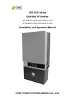
CPS SC Series Grid-tied PV Inverter CPS SC100KT-O/US-480 Installation and Operation Manual Version: 1.1 CHINT POWER SYSTEMS AMERICA CO., LTD. Address: 700 International Parkway, Suite 102 Richardson, Texas Zip Code: 75081 Web: www.chintpower.com/na Email: [email protected] Service Hotline: 855-584-7168 SHANGHAI CHINT POWER SYSTEMS CO., LTD. All rights reserved. Specifications and designs included in this manual are subject to change without notice. CHINT POWER 2013/06-MKT PN: 9.0020.0041F0 Table of Contents Before You Start… ................................................................................... 1 Chapter 1 IMPORTANT SAFETY INSTRUCTIONS ............................... 2 Chapter 2 Overview ............................................................................... 8 2.1 Inverter for grid-tied PV systems ................................................ 8 2.2 Product type description ............................................................. 8 2.3 Product features ......................................................................... 9 2.4 Inverter circuit structure .............................................................. 9 2.5 Appearance description .............................................................. 10 Chapter 3 Installation ............................................................................ 12 3.1 Basic requirements ..................................................................... 13 3.2 Checklist of installation tools ...................................................... 14 3.3 Mechanical installation ............................................................... 14 3.4 Electrical installation ................................................................... 20 3.4.1 DC connection .................................................................... 26 3.4.2 AC connection..................................................................... 31 3.4.3 Ground connection ............................................................. 32 3.4.4 Communication connection................................................. 33 3.4.5 Connection of dry contact ................................................... 36 3.4.6 Installation of bottom filter and baffles................................. 37 Chapter 4 Initial On-grid Testing .......................................................... 38 4.1 Testing steps .............................................................................. 38 4.2 Testing procedure statement ...................................................... 39 4.2.1 Check the appearance of inverter ....................................... 39 4.2.2 Check AC connection ......................................................... 39 4.2.3 Check DC connection ......................................................... 40 4.2.4 Turn on AC circuit breaker .................................................. 41 4.2.5 System self-check and time set-up ..................................... 41 4.2.6 Set up AC operational parameters ...................................... 42 4.2.7 Set up DC operational parameters ..................................... 42 4.2.8 Set up MPPT operational parameters ................................ 43 4.2.9 Turn on DC circuit breaker.................................................. 43 4.2.10 Power train of self-check .................................................. 43 4.2.11 Start up inverter ................................................................ 46 Chapter 5 Operation ............................................................................. 47 5.1 Shut-down and Start-up ............................................................. 47 5.1.1 Shut-down .......................................................................... 47 5.1.2 Start-up ............................................................................... 50 5.2 Operation mode ......................................................................... 51 5.3 Troubleshooting ......................................................................... 54 Chapter 6 Human Machine Interface ................................................... 67 6.1 Description of LCD panel ........................................................... 67 6.2 Operation state .......................................................................... 70 6.3 Interface and menu functions ..................................................... 71 6.3.1 Interface types .................................................................... 71 6.3.2 Main operation interface ..................................................... 74 6.3.3 Operation information ......................................................... 75 6.3.4 Present fault ....................................................................... 76 6.3.5 History ................................................................................ 76 6.3.6 System setup...................................................................... 78 6.3.7 Power Dispatch .................................................................. 80 6.3.8 System protection parameters setup .................................. 82 Chapter 7 Service and Maintenance.................................................... 86 7.1 Maintenance instruction of filter net ........................................... 86 7.1.1 Maintenance of filter net on the top .................................... 86 7.1.2 Maintenance of filter net at the bottom ............................... 88 7.2 Maintenance of fan tray assembly ......................................... 89 Chapter 8 Technical Data ..................................................................... 91 Chapter 9 Limited Warranty ................................................................. 96 Before You Start… This manual contains important information regarding installation and safe operation of this unit. Be sure to read this manual carefully before using. Thanks for choosing this Grid-tied PV Inverter (referred to in this manual as “PV Inverter”, or simply “Inverter”). This Grid PV Inverter is a highly reliable product due to its innovative design and perfect quality control. Such an Inverter is used in high demand, grid-tied PV systems. If you encounter any problems during installation or operation of this unit, first check this manual before contacting your local dealer or supplier. Instructions inside this manual will help you solve most installation and operation difficulties. Please keep this manual on hand for quick reference. 1 Chapter 1 IMPORTANT SAFETY INSTRUCTIONS (SAVE THESE INSTRUCTIONS) Please read this user manual carefully before undertaking the installation. CPS reserves the right to refuse warranty claims for equipment damage if the user fails to install the equipment as per the instructions in this manual. DANGER: DANGER indicates a hazardous situation which, if not avoided, will result in death or serious injury. WARNING: WARNING indicates a hazardous situation which, if not avoided, could result in death or serious injury. CAUTION: CAUTION indicates a hazardous situation which, if not avoided, could result in minor or moderate injury. NOTICE: NOTICE indicates a hazardous situation which, if not avoided, could result in equipment working abnormally or property loss. INSTRUCTION: INSTRUCTION indicates important supplementary information or provides skills or tips that can be used to help you solve a problem or 2 save you time. Warnings and symbols in this document Markings on the product HIGH VOLTAGE: The product works with high voltages. All work on the product must only be performed as described in this document. HOT SURFACE: The equipment is designed to meet international safety standards, but surfaces can become hot during operation. Do not touch the heat sink or peripheral surfaces during or shortly after operation. EARTH GROUND: This symbol marks the location of grounding terminal, which must be securely connected to the earth through the PE (protective earthing) cable to ensure operational safety. 3 DANGER: Please disconnect the inverter from AC grid and PV modules before opening the equipment. When the PV array is exposed to light, it supplies DC voltage to this equipment. Make sure hazardous high voltage and energy inside the equipment has been discharged. Do not operate or maintain the inverter until at least 8 minutes after disconnecting all sources from DC and AC sides. DANGER: Make sure that equipment is grounded properly. If a ground fault is indicated, the grounding conductors are probably ungrounded and energized. WARNING: All the installation and wiring connections should be performed only by qualified technical personnel. Disconnect the inverter from PV modules and the Power Grid before maintaining and operating the equipment. WARNING: 4 When the connected PV module is exposed to the sunlight, it generates DC voltage and charges the DC bus capacitors of the inverter. Electric charges are still stored in the capacitors even the input of the PV inverter is turned off. Therefore, equipment shall not be maintained until 60 minutes after all inputs are cut off or the “De-energy” command is carried out successfully. WARNING: Shut down the inverter before maintaining the inverter. Disconnect the inverter from PV panels and the Power Grid and make sure there is no electric charge left in the inverter before the maintenance. CAUTION: Although designed to meet international safety standards, the PV-Inverter can become hot during operation. Do not touch the heat sink or peripheral surfaces during or shortly after operation. NOTICE: This inverter is designed to connect AC power only to the public grid. Do not connect the AC output of this equipment directly to any private AC power equipment. 5 NOTICE: Please choose the type of inverter based on the way of DC grounding system! Change of PV grounding in the inverter is prohibited without permission. Please contact our after-sale service personnel if the change of grounding in the inverter is necessary. NOTICE: If the polarity of the DC cables is not correct, the inverter will be damaged. NOTICE: Do not install the inverter under direct sunlight to avoid conversion efficiency de-rating caused by excessively high temperature. NOTICE: To ensure operational safety, run the initial on-grid testing before operating on the inverter. INSTRUCTION: Steel conduits as the cable protector need to be prepared before installation. 6 INSTRUCTION: If no voltage is detected, check whether the connection from DC source to the inverter is correct. Maybe the combiner boxes are not properly connected or there is a short circuit in the DC cables. 7 Chapter 2 Overview 2.1 Inverter for grid-tied PV systems CPS SC100KT-O/US-480 inverter can be applied to various commercial rooftop systems and distributed power station systems. Normally, the system mainly consists of PV modules, DC power distribution equipments, PV inverter and AC power distribution equipments (Figure 2-1). The inverter converts the DC energy from PV modules to the AC energy that is compatible with the public grid. The AC energy can be used directly by the local load, or it can be sold to your energy provider. DC power AC power distribution distribution equipments equipments Bidirectional electric meter AC Grid Figure 2-1 Grid-tied PV system 2.2 Product type description CPS SC100KT-O/US-480 is a PV inverter integrated with a low frequency isolation transformer for indoor and outdoor application. The suffix “US” means that this model of inverter passes the UL and CSA certifications and is 8 specialized for the American market. 2.3 Product features CPS SC100KT-O/US-480 inverter incorporates the advanced MPPT controlling technology and variable structure modulation strategy to minimize the energy loss. The design with transformer has the benefit of connecting the inverter to the low-voltage grid more conveniently. The enclosure of inverter conforms to the NEMA 3R (IP44) protection class, which enables the inverter to be used in the outdoor environment. Besides, the smart DSP control, complete protection function and advanced thermal design guarantee the inverter with high reliability. 2.4 Inverter circuit structure The basic schematic diagram of CPS SC100KT-O/US-480 inverter is shown in Figure 2-2. The output of PV modules first passes through DC circuit breaker. The inverter converts DC voltage to 3-phase AC voltage. The 3-phase AC voltage will be removed of high frequency component by the sine wave filter, then stepped up and isolated by the low frequency transformer and go through AC contactor, AC EMI filter, circuit breaker, at last, be fed to the LV grid. 9 CPS SC100KT-O/US-480 3~ AC EMI Filter Surge Protector PV- = Sine Wave Filter PV+ DC EMI Filter Surge Protector Inverter L1 L2 L3 G IPV PWM UPV+ UPV- SPU GFDi RS485 Ia Ib Ic JCC Ua Ub Uc RS485+ RS485- Figure 2-2 Schematic diagram 2.5 Appearance description 1 2 3 4 5 6 Figure 2-3 Appearance sketch of CPS SC100KT-O/US-480 10 Description of main components (shown in Figure 2-3): 1. Roof Panel 2. Operation buttons and LCD display panel with protection cover 3. Emergency stop button 4. Door lock 5. AC circuit breaker 6. DC circuit breaker 11 Chapter 3 Installation Below is the installation instruction of the inverter. Please read carefully and install the product step-by-step. 1. CPS SC100KT-O/US-480 Check and make sure that the following items are included in the package before installation, as shown in Table 3-1. Table 3-1 Main items Item Q’ty Note 1 Grid-tied PV inverter (1) CPS SC100KT-O/US-480 Grid-tied PV inverter Contains all necessary (2) Accessory kit 1 accessories The (2) Accessory kit contains items listed below: Table 3-2 Accessories Item Q’ty Purpose User manual 1 Installation and operation 12 manual For maintenance and Warranty service card 1 repair Bottom baffle 2 For air convection Bottom filter 1 For dust proof M4 screw 8 For bottom baffles 3.1 Basic requirements NOTICE: Do not install the inverter under direct sunlight to avoid conversion efficiency de-rating caused by excessively high temperature. Check and make sure that the ambient temperature of the installation environment is -25 C ~+60C; Make sure that the public power grid voltage is 422~528Vac and the grid frequency is 57.0~60.5Hz; Permission of grid connection has been granted by the local electric power authority; Installation personnel must be qualified electricians or people who have received professional training; 13 Sufficient convection space; Away from flammable and explosive substances; 3.2 Checklist of installation tools The checklist of tools for installation of the product: Table 3-3 No. Name Specification Function 1 Spline screwdriver T25 For screws on the backboard PH2 For M3 and M4 screws Phillips head 2 screwdriver 3 Open end wrench 0.55 inch For M8 screws 4 Open end wrench 0.67 inch For M10 screws 5 Straight screwdriver 0.12 inch For screws on dry contact 6 Sleeve 0.28 inch For M4 nuts 7 Torque wrench 132.74 lb-In. For M10 screws 3.3 Mechanical installation (1) Dimensions Dimensions of CPS SC100KT-O/US-480 inverter are shown in Figure 3-1. 14 72.83in. 47.24in. n. 65i 34. Figure 3-1 Sketch of dimensions There are 2 ways to install the foundation of inverter: (1) The dimensions of foundation installation for the first way are shown in Figure 3-2 (a). Please pay attention to the direction of the 4 fixing plates at the bottom. 15 47.24in. 4.33in. 38.58in. 1.97in. 2.64in. 25.39in. 34.65in. D=0.63in. Fixing Conduit area plate 3.94in. 4.13in. 13.31in. 1.97in. Figure 3-2 (a) Sketch of foundation installation dimensions Place the fixing plates inward, as shown in Figure 3-2 (b). Fixing plate Figure 3-2 (b) Inward direction to place fixing plates 16 (2) The dimensions of foundation installation for the second way are shown in Figure 3-3 (a). Please pay attention to the direction of the 4 fixing plates at the bottom. 50.79in. 1.10in. 48.58in. 47.24in. 2.64in. 1.97in. D=0.63in. 25.39in. area Fixing 13.31in. 3.94in. 4.13in. plate 34.65in. Conduit 1.97in. Figure 3-3 (a) Sketch of foundation installation dimensions Place the fixing plates outward (Figure 3-3 (b)). 17 Fixing plate Figure 3-3 (b) Outward direction to place fixing plates Requirements of inverter installation: According to the installation dimensions shown in Figure 3-2 (a) and 3-3 (a), secure the inverter on the hard ground or channel steel chassis with M12 foundation bolts through the 8 holes with a diameter of 0.63 inch at the bottom of the equipment. Front door: A 25.6-inch space should be reserved to ensure that the front door can be opened and closed freely. Back: A 31.5-inch space should be reserved for maintenance. The weight of the inverter is approximately 1984.2 pounds. Make sure that the mounting place can bear the weight. Two approaches are recommended to lift the machine, i.e. lifting with a crane or a forklift: 18 Lifting with a crane: Before lifting the machine, adjust the width of the forklift arm within 16.5~33.5 inches and insert the fork into the bottom of the machine from the back and lift it to the appropriate location for installation as shown in Figure 3-4. Figure 3-4 Diagram of lifting with a crane Lifting with a forklift: Adjust the width of the forklift arm within 16.5~33.5 inches and insert the fork into the bottom of the machine from the back and lift it to the appropriate 19 location for installation as shown in Figure 3-5. >16.54in. <33.46in. Figure 3-5 Diagram of lifting with a forklift 3.4 Electrical installation Open the front door of the machine. Proceed as shown in Figure 3-6. 1、Turn the handle bar of DC circuit breaker anti-clockwise to horizontal 20 position. 2、Turn the handle bar of AC circuit breaker anti-clockwise to horizontal position. 3、Unlock the door with the key. Pull the lock handle 45 degree outward to open the front door. 1 3 2 Figure 3-6 Diagram of opening front door 4、After opening the front door, remove the transparent Plexiglas cover for wiring. There are two ways to connect the external cables to the inverter: wiring from the bottom and wiring from the left side. (1) Wiring from the bottom: There are also 2 ways to connect cables from the bottom of the inverter. ① Routing from rectangular conduit areas: 21 Remove the two bottom covers with a Phillips head screwdriver and connect cables to the inverter through the rectangular conduit areas, as shown in Figure 3-7. DC bottom cover AC bottom cover Figure 3-7 Routing from rectangular conduit areas ② Routing from round holes on the two bottom covers: (a) Remove the cover screws, put the screws aside, and then take off the two covers; (b) Punch two holes on the DC bottom cover for DC conduits, as shown in Figure 3-8; (c) Punch three holes on the AC bottom cover—one for the communication conduit, one for the AC conduit and one for 22 grounding conduit, as shown in Figure 3-9; For DC conduit Figure 3-8 Holes on DC bottom cover For communication conduit For AC conduit For grounding conduit Figure 3-9 Holes on AC bottom cover (d) Install steel connectors on the DC and AC bottom covers and check the seal of the cover; (e) Connect the steel conduits to these connectors; 23 (f) Restore the two covers to the inverter and attach the screws; (g) Put the cables through steel conduits to connect to the inverter, as shown in Figure 3-10. Figure 3-10 Routing from round holes on the two bottom covers (2) Wiring from the left side: (a) Remove the screws on the left side cover with a Phillips head screwdriver, put the screws aside, and then take off the cover; (b) Punch five holes on the left bottom cover for steel conduits, as shown in Figure 3-11; 24 For For DC communica conduit tion conduit For AC For conduit Grounding conduit Figure 3-11 Holes on the left side cover (c) Install steel connectors on the left side cover and check the seal of the cover, as shown in Figure 3-12; Grounding DC AC Com. Figure 3-12 Installation of steel connectors 25 (d) Connect the steel conduits to these connectors; (e) Restore the cover to the inverter and attach the screws; (f) Put the cables through steel conduits to connect to the inverter, as shown in Figure 3-13; Figure 3-13 Wiring from the left side 3.4.1 DC connection (1) To ensure the optimal performance of the inverter, please read the following guidelines before DC connection: (a) First, make sure that the maximum open circuit voltage of the PV modules is lower than 600Vdc under any conditions; (b) Ensure that the polarity of DC input is correct, i.e. the positive pole of PV module is connected to the positive pole of the inverter’s DC 26 input, and the negative pole of PV module is connected to the negative pole of the inverter’s DC input; (c) The Max. DC input current of the inverter is 350A, so 2AWG~ 3/0AWG copper cables with an insulation rating of 194℉ are recommended for inverter’s DC input. The DC connection requirement is shown in Table 3-4: Table 3-4 4 strings 3 strings 2 strings Positive 2AWG(35mm²) 1/0AWG (50 mm²) 3/0AWG (95 mm²) Negative 2AWG(35mm²) 1/0AWG (50 mm²) 3/0AWG (95 mm²) (d) Reserve a hole of 11mm diameter on the copper bar. Select the following recommended bolts to tighten the cables, see Table 3-5: Table 3-5 Type Length Torque Value Metric Bolt M10 25mm 24.6N-M (217.4Lb-In.) American 3/8’ 1’ 24.6N-M (217.4Lb-In.) Bolt INSTRUCTION: The standard DC configuration is 4 strings. Other configurations are 27 also available by changing corresponding fuses. The specification of fuses for DC input strings is shown in Table 3-6. Table 3-6 String Fuse Rated # Un(V) Fuse Rated Interrupting Rating Note In(A) 2 1000 275 150kA Minimum set 3 1000 185 150kA Minimum set 4 1000 140 150kA Default set The position of DC fuses is shown in Figure 3-14. Fuse Figure 3-14 Position of DC fuses 28 (2) Confirm that the input PV modules are of the same specifications and types before connection of DC input; (3) Connect the DC cables to the inverter’s copper bar terminals on DC side according to the Table 3-7. In Table 3-6, CPS SC100KT-O/US-480, this type of inverter means that the negative pole of DC input needs to be connected to the Return ground bar and CPS SC100KT-OPG/US-480, this type of inverter means that the positive pole of DC input needs to be connected to the Return ground bar. Table 3-7 Type of Inverter Default way of grounding PV - PV+ CPS SC100KT-O/US-480 Negative grounding Return Hot CPS SC100KT-OPG/US-480 Positive grounding Hot Return NOTICE: Please choose the type of inverter based on the way of DC grounding system! Change of PV grounding in the inverter is prohibited without permission. Please contact our after-sale service personnel if the change of grounding in the inverter is necessary. 29 Hot Return PV– PV+ Figure 3-15 DC connection of CPS SC100KT-O/US-480 Hot Return PV+ PV– Figure 3-16 DC connection of CPS SC100KT-OPG/US-480 30 The two schematic diagrams of wire connection are shown in Figure 3-17. Outside the inverter Outside the inverter Inside the inverter Hot + = PV+ - PVReturn Inside the inverter Hot + = PV- ~ - PV+ Return GFDI ~ GFDI Positive ground Negative ground (a) (b) Figure 3-17 Schematic diagram on DC side 3.4.2 AC connection Connect the AC output of PV inverter to the AC cabinet or the power grid: (1) Use the recommended copper cables with an insulation rating of 194℉. The AC calbe requirement is shown in Table 3-8: Table 3-8 L1 Wire diameter L2 2 2/0AWG (70mm ) L3 2 2/0AWG (70mm ) 2 2/0AWG (70mm ) Select the following recommended bolts to tighten the cables in Table 3-9: Table 3-9 Metric Bolt Type Length Torque Value M10 25mm 10N-M (88.5Lb-In.) 31 American 1’ 3/8’ 10N-M (88.5Lb-In.) Bolt (2) Connect the power grid A, B, C cables to the L1, L2, and L3 te rminals of the inverter, as shown in Figure 3-18: AC output cables L1 L2 L3 Figure 3-18 AC output connection (3) Make sure that all cables are well connected on the L1, L2, and L3 terminals. 3.4.3 Ground connection The ground copper bar is located at the bottom right corner of the inverter, as shown in Figure 3-19. 32 Gnd copper bar Figure 3-19 Ground connection Connect the Ground (PE) cable to the Gnd terminal of Gnd copper bar. The Ground connection requirement is shown in Table 3-10. Table 3-10 Item Gnd (PE) Wire diameter 2AWG (35mm ) Nut M8 Torque value 12.5N-M (113.5 Lb-In.) 2 3.4.4 Communication connection RS485 communication connection: The signal pinboard on the inverter has 2 RS485 communication ports, which are RS485-1 and RS485-2 for field connections, as shown in Figure 33 3-20. RS485-1 RS485-2 Figure 3-20 Signal cable terminals for communication (1) The communication of one single local inverter is to connect the RS485 communication bus cable through the RS485-1 or RS485-2 port of the inverter directly. Shielded twisted pair (STP) cable should be used for RS485 communication with the maximum allowable length of 3280 feet. Wiring requirement of RS485-1/2 is shown in Table 3-10: Table 3-11 RS485-1/2 wiring requirement 34 No. Color Function 1 White orange 485+ 2 Orange N.C. 3 White green 485- 4 Blue N.C. 5 White blue N.C. 6 Green N.C. 7 White brown N.C. 8 Brown N.C. The wires are labeled 1~8 from left to right, as shown in Figure 3-21: Figure 3-21 Diagram of RS485-1/2 wiring (2) For remote monitoring of more inverters, connect the RS485-2 port of one inverter to the RS485-1 port of another inverter and then connect to the 35 data logger through the RS485 communication bus cable. For more information about CPS monitoring solutions, please contact our after-sales service center. 3.4.5 Connection of dry contact The connection of dry contact is shown in Figure 3-22. The two terminals are potential-free contacts for fault alarming of the inverter. The wiring requirement is shown in Table 3-11. Dry contact 干接点 Figure 3-22 Diagram of Dry contact connection Table 3-12 Function Wire diameter Signal type Inverter fault alarm 18AWG (0.810mm ) Dry contact 2 (MAX 240VAC 2A) 36 3.4.6 Installation of bottom filter and baffles After all wire connections are completed, insert the filter into the filter slot at the bottom of the inverter. Then install the front and back baffles with the eight M4 screws (in the accessory pack), as shown in Figure 3-23. Baffle Filter Baffle Figure 3-23 Diagram of bottom filter and baffles installation 37 Chapter 4 Initial On-grid Testing To ensure operational safety, initial on-grid testing is required as per the instructions in this chapter before connecting the inverter to PV panels and grid power after the installation of CPS SC100KT-O/US-480. 4.1 Testing steps Take the following steps for the initial on-grid test: (1) Check the appearance of inverter (2) Check AC connection (3) Check DC connection (4) Turn on AC circuit breaker (5) System self-check and time setup (6) Set up AC operational parameters (7) Set up DC operational parameters (8) Set up MPPT operational parameters (9) Turn on DC circuit breaker (10) Power train of self-check (11) Start up inverter 38 INSTRUCTION: Please refer to “5.3 Troubleshooting” or contact our after-sale service personnel if any problem is found during the testing. 4.2 Testing procedure statement 4.2.1 Check the appearance of inverter (1) Check whether the inverter has any visible abnormalities. Make sure that the DC and AC circuit breakers are turned off. Open the front door of the inverter and ensure the electrical components and connections are normal. (2) Check and make sure that all the cables are properly connected and free of defects. (3) Correct and record any identified problems. 4.2.2 Check AC connection (1) Check whether the power grid A, B, C, and PE cables are properly torqued on the appropriate L1, L2, L3 and Ground terminals. (2) Before connecting the inverter to the power grid, measure the line to line voltage between terminals of AC cables. The voltage of L1-L2, L2-L3 and L3-L1 should be within the range of 422-528Vac. (3) If abnormal power grid voltage or no voltage is detected, please 39 reconfirm the power transmission from the power grid to the inverter. If there is nothing wrong with the power transmission, check whether the AC connection is correct. (4) Correct and record any identified problems. 4.2.3 Check DC connection (1) Check whether the PV cables are properly torqued on the appropriate DC terminals. (2) Put through the DC input from PV panels, combiner boxes or other DC distribution equipments and then measure the voltage between Hot and Return bars. INSTRUCTION: If no voltage is detected, check whether the connection from DC source to the inverter is correct. Maybe the combiner boxes are not properly connected or there is a short circuit in the DC cables. (3) Confirm whether the polarity of DC connection is correct. NOTICE: If the polarity of the DC cables is not correct, the inverter will be 40 damaged. (4) Correct and record any identified problems. 4.2.4 Turn on AC circuit breaker (1) Close the front door of the inverter. (2) Turn on the AC circuit breaker. The auxiliary power supply of the inverter will be energized and the control circuit be activated. (3) Check carefully whether there is any abnormality. (4) Turn off the AC circuit breaker immediately if there is any abnormality. Reconfirm whether the previous testing steps are correct. Stop testing if anything abnormal occurs. 4.2.5 System self-check and time set-up (1) “Sys. Checking” will be indicated on the LCD when the AC circuit breaker is turned on. (2) The inverter will stand by after the self-check of system (about 30 seconds) is completed. Meanwhile, fault indication interface will be shown on the LCD if any malfunction occurs. The specific fault indication and solution are available to be found in “5.3 Troubleshooting”. Besides, since the DC circuit breaker is not turned on, the fault 41 “Warn0040” will be indicated on the LCD. Please ignore the fault and keep the DC circuit breaker in OFF state. (Please don’t turn on the DC circuit breaker until it is allowed in the Chapter 4.2.9). (3) Enter the “4 SysTime” menu and set up the present date and time according to “6.3.6 System setup”. 4.2.6 Set up AC operational parameters Enter “1 SysPara” menu according to “6.3.7 System protection parameter setup”. (1) Check the AC voltage, frequency protection value and time of protection actions. (2) Change the parameters referring to the “Protection Parameters Table” in Chapter 6.3.7 if necessary. (3) Record the changed parameters. 4.2.7 Set up DC operational parameters (1) Check the PV startup voltage and startup time of the inverter. (2) Change the parameters if necessary. (3) Record the changed parameters. 42 4.2.8 Set up MPPT operational parameters (1) Check the active derating and reactive compensation parameters of the inverter; (2) Set the active power derating to 10%. (3) Record the changed parameters. 4.2.9 Turn on DC circuit breaker (1) Turn off the AC circuit breaker. (2) Turn on the DC circuit breaker to provide the PV power supply to the DC side of the inverter. (3) Check carefully whether there is abnormality. (4) Turn off the DC circuit breaker if there is any abnormality. Reconfirm whether the previous testing steps are correct. Stop testing if anything abnormal occurs. 4.2.10 Power train of self-check (1) Confirm that the front door of the inverter is closed and locked. (2) Turn on the AC circuit breaker. (3) Wait for the inverter to stand by, the status of which will be indicated on the LCD. 43 (4) Select “2 PowerTrain” on the LCD and press “ENT” according to “6.3.6 System setup”. Then self-check interface will be indicated on the LCD. (Figure 4-1) After pressing “ENT”, the system begins self-checking. (Figure 4-2) PowerTrain? Figure 4-1 Self-check confirmation interface PowerTrain.. Figure 4-2 System self-checking (4) If “Low PV Volt” is indicated on the LCD, as shown in Figure 4-3, check whether the DC connection is correct and whether the DC voltage is below 300V (subject to grid voltage). 44 Low PV Volt Figure 4-3 Low Volt (5) If “PowerTrainFualt” is indicated on the LCD, as shown in Figure 4-4, check whether the DC circuit breaker is turned on. Then check whether the inverter is in “ON State” according to “6.3.6 System setup”. If the fault still occurs when the DC circuit breaker is turned on and the inverter is “ON State”, turn off the AC and DC circuit breakers immediately and then contact our after-sales service personnel. PowerTrainFault Figure 4-4 Self-check fails (6) If the self-check is successful, “PowerTrain OK” will be indicated on the LCD, as shown in Figure 4-5. Press ESC to return to the main menu. 45 PowerTrain OK Figure 4-5 Self-check OK 4.2.11 Start up inverter (1) If the PV voltage reaches the startup voltage (subject to the grid voltage and 330V is the default minimum voltage.) and the grid voltage meets the requirement of grid connection, the inverter will be energized to start up after 7-15 minutes under stand-by mode. The largest output power is 10% of the rated power. (The active power derating was set to 10%.) (2)If nothing abnormal happens, the active derating value can be gradually increased to 100%. (3)Check all the operation information on the LCD. (4)Turn off the AC and DC circuit breaker or press the “emergency stop button” if anything abnormal occurs. 46 Chapter 5 Operation NOTICE: To ensure operational safety, run the initial on-grid testing before operating on the inverter. 5.1 Shut-down and Start-up 5.1.1 Shut-down Manual shut-down : Normally, manual shutdown is not necessary. But the inverter can be shut down manually for maintenance or user’s needs. (1) Move the cursor from the main operation interface to “4 Setting” according to “6.3.6 System setup”. Press ENTER and go to submenu “1 ON/OFF”. The inverter will be shut down and enter “OFF State” after moving the cursor to “OFF” and press ENTER. (2) Press the “emergency stop button” on the panel to shut down the inverter in case of emergencies. Then the fault alert “EmergencyStp” will be indicated on the LCD and the inverter will stop working. Once the “emergency stop button” is restored, the fault alert will be eliminated and the inverter will restart working automatically. Automatic shut-down: The inverter will be shut down automatically and 47 enter standby mode when the output voltage of PV panel is lower than the set point (300Vdc minimum), or AC power grid fails; or the ambient temperature exceeds the normal range. The inverter will restart working automatically when the appropriate grid-connection condition is detected. Manual Shut-down for maintenance: If service personnel need to maintain or repair the inverter, please follow the following steps. (1) Shut down the inverter according to the manual shut-down steps. Turn off the DC circuit breaker and ensure that the AC circuit breaker is turned on. (2) Referring to “6.3.6 System setup”, move the cursor from the main operation interface to “4 Setting”, press ENTER and go to submenu “6 OtherCmd”. Then move the cursor to “1 De-energy” and press ENTER, as shown in Figure 5-1. After pressing ENTER to confirm, the DC bus capacitor begins to discharge, as shown in Figure 5-2. De-energy? Figure 5-1 Inverter de-energy interface 48 De-energy.. Figure 5-2 De-energy ongoing (3) When “De-energy” is successfully completed (Figure 5-3), press ESC to return to the main menu. Check the PV voltage on the LCD according to “6.3.3 Operation information” or check the voltage of DC bus capacitor with a voltmeter. Don’t turn off the AC circuit breaker or perform maintenance to the inverter until the DC bus capacitor is discharged to safe voltage, as shown in Figure 5-3. De-energy OK Figure 5-3 De-energy OK interface (4) If “De-energy” fails, as shown on the LCD in Figure 5-4. It takes at least 60 minutes for the inverter to discharge automatically by turning off the AC circuit breaker. The inverter should not be maintained until the voltmeter 49 shows that there is no electric charge left in the DC bus capacitor. InverterErr Figure 5-4 De-energy error interface (5) If the DC circuit breaker is not turned off, LCD will remind the user to “TurnOff DC Break”, as shown in Figure 5-5. Please turn off the DC circuit breaker and press “ENT” to continue discharging. TurnOff DC Break Figure 5-5 Turnoff DC circuit breaker 5.1.2 Start-up Turn on the DC and AC circuit breakers. Manual start-up: Manual start-up is required after a manual shut-down or a fault shut-down by the user. Move the cursor from the main operation interface to “4 Setting” according 50 to “6.3.6 System setup”. Press ENTER and go to submenu “1 ON/OFF”. Then move the cursor to “ON” and press ENTER to start the inverter. Then the inverter will start up and operate normally if the start-up condition is met. Otherwise, the inverter stands by. Automatic start-up: Confirm that the inverter is “ON State” at first. The inverter will start up automatically when the output voltage (Default value is 330V, which can be adjusted according to “6.3.6 System setup”.) of PV panel meets the set point, AC power grid is normal, and the ambient temperature is within allowable operating range. 5.2 Operation mode There are 4 operation modes. The following are corresponding indications for each mode. (1) System check mode is shown in Figure 5-6: System is in self check status when inverter is energized. The program will complete initialization during this process. 51 Sys.Checking >>>>>> Figure 5-6 System self check ongoing (2) Standby mode, as shown in Figure 5-7: After self check is completed, the inverter will turn into standby mode if the output voltage of PV panel, AC power grid or ambient temperature does not meet the startup conditions. But the inverter will continue to check whether the startup conditions are met in standby mode until it comes back to normal operation mode. If the warning SPICommErr occurs and the FAULT LED is blinking, the operation mode shown by LCD may not be correct even if LCD shows “Standby”. Please refer to the solution of SPICommErr in 5-1 Troubleshooting Table on Page 49. Standby >>>>>> Figure 5-7 Inverter system in standby (3) Normal operation mode, as shown in Figure 5-8: 52 The inverter will turn from standby into normal operation mode when the startup conditions are met as long as the inverter is “ON State”. In this mode, the inverter converts DC generated by PV modules to AC and feeds the AC to the power grid. Under the normal operation mode, the inverter will maximize the DC output from PV panels in the manner of MPPT (Maximum Power Point Tracking). Meanwhile, the inverter will check the power grid and PV output voltage constantly. Once anything abnormal occurs, the inverter will stop working and take self-protection. Figure 5-8 Normal operation mode interface (4) Fault mode, as shown in Figure 5-9: The inverter will stop working, disconnect from the power grid and turn into fault mode when the inverter or power grid fails. Check the fault information on the LCD according to “6.3.4 Present fault” and “6.3.5 History”. To find the specific cause and solution, you can refer to Table 5-1 in “5.3 Troubleshooting”. 53 GridV.OutLim Figure 5-9 Fault indication interface 5.3 Troubleshooting Before you contact our after-sales service center, you are able to find most faults and solutions in Table 5-1 for the troubleshooting. There are three kinds of fault alert statuses: Warn, Protect and Fault. When there is a “Warn”, the system only reminds customers of the problem while it doesn’t change the operation mode. When there is a “Protect”, the system will turn into fault mode and come back to normal when the “Protect” disappears. When there is a “Fault”, the system will stop working and remain standby until resetting the system or repair the inverter to eliminate the fault. Two ways of system reset are listed as follows: 1. Turn off the AC circuit breaker, wait for 5 seconds and turn on the AC circuit breaker again to recharge the system control unit. If the system check is passed, the inverter will turn into normal operation mode. 2. Run the “2 Restart” command to reboot the system according to “6.3.7 54 System protection parameter setup”. The causes of fault can be identified based on the faults listed in Table 5-1. Please contact our after-sales service if the fault still exists. WARNING: Shut down the inverter before maintaining the inverter. Disconnect the inverter from PV panels and the Power Grid and make sure there is no electric charge left in the inverter before the maintenance. 55 Table 5-1 Troubleshooting Table Definition: Communication inside inverter fails Possible causes: 1. Communication circuits inside inverter are loose; 2. LCD software problem; 1. SPICommErr 3. Inverter software problem; Recommended solutions: Warn 1. Observe for 5 minutes and see whether the alarm will be eliminated automatically; 2. Turn off 3-phase working power supply and then reboot the system; 3. Contact our after-sales service center. Definition: 2. Warn0010 Fan (invisible from outside) inside inverter is working abnormally 56 Possible causes: 1. Fan is blocked; 2. Power supply circuit of the fan has problem; 3. Fan state test circuit is loose; 4. Fan service life has expired; 5. Inverter software problem Recommended solutions: 1. Observe for 5 minutes and see whether the alarm will be eliminated automatically; 2. Switch off 3-phase working power supply and then reboot the system; 3. Contact our after-sales service center. Definition: Eeprom error 3. Warn0030 Possible causes: Internal storage error Recommended solutions: 1. Observe for 5 minutes and see whether the 57 alarm will be eliminated automatically; 2. Contact our after-sales service center Definition: DC circuit breaker error Possible causes: 1. PV positive pole and negative pole are connected reversely; 2. PV over-current; 3. DC breaker is damaged; 4. DC circuit breaker is turned off 4. Warn0040 Recommended solutions: 1. Observe for 5 minutes and see whether the alarm will be eliminated automatically; 2. Check DC breaker; 3. Check PV cable connection; 4. Check whether the sunlight is too strong or the configuration of PV panel is appropriate; 5. Contact our after-sales service center 5. Warn0050 Definition: 58 Temperature sensor error Possible causes: 1. Temperature inside inverter exceeds normal range; 2. Temperature sensor has problem Recommended solutions: 1. Observe for 5 minutes and see whether the alarm will be eliminated automatically; 2. Check whether the operation temperature is ﹣25℃~60℃; 3. Contact our after-sales service center Definition: Inside warning Possible causes: 6. Inverter has inside problem Warn0010~0150 Recommended solutions: 1. Observe for 5 minutes and see whether the alarm will be eliminated automatically; 59 2. Contact our after-sales service center Definition: Ambient temperature or temperature inside inverter is too high Possible causes: 1. Ambient temperature outside the inverter is too high; 2. Radiation air inlet is blocked; Too much dust is on the filter net; 3. Radiation fan is blocked without rotation Protect 1. TempOver Recommended solutions: 1. Confirm that external ambient temperature is within the specified range of operating temperature; 2. Check whether radiation air inlet is blocked and filter net has too much dust; 3. Whether radiation fan is blocked; 4. Observe for 30 minutes and see whether the alarm will be eliminated automatically; 60 5. Contact our after-sales service center Definition: Grid voltage exceeds the allowable range, or power grid is not detected Possible causes: 1. Grid voltage is abnormal; 2. Power grid breaks down; 3. Cable connection between the inverter and the grid is disconnected; 2. GridV.OutLim 4. Inverter has an internal fault Recommended solutions: 1. Observe for 10 minutes and see whether the alarm will be eliminated automatically; 2. Check whether the grid voltage is within the allowable range; 3. Check whether the cable connection to the grid is disconnected or abnormal; 4. Contact our after-sales service center 3. GridF.OutLim Definition: 61 Grid voltage frequency is abnormal, or grid is not detected Possible causes: 1. Grid frequency is abnormal; 2. Power grid breaks down; 3. Cable connection between the inverter and the grid is disconnected; 4. Inverter has an internal fault Recommended solutions: 1. Observe for 10 minutes and see whether the alarm will be eliminated automatically; 2. Check whether the grid frequency is within the allowable range; 3. Check whether the cable connection to the grid is disconnected or abnormal; 4. Contact our after-sales service center Definition: 4. PV.VoltOver PV voltage exceeds the allowable value Possible causes: 62 1. PV over-voltage 2. Inverter has an internal fault Recommended solutions: 1. Observe for 30 minutes and see whether the alarm will be eliminated automatically; 2. Check whether PV voltage exceeds the allowable range; 3. Disconnect from PV input, wait for 5 minutes and reconnect to PV input; 4. Contact our after-sales service center Definition: PV panel is connected reversely Possible causes: 1. PV positive pole and negative pole are 5. PV.Reverse connected reversely; 2. Inverter has an internal fault Recommended solutions: 1. Check whether positive pole and negative pole are connected reversely; 63 2. Contact our after-sales service center Definition: AC contactor is abnormal Possible causes: 6. AC.ContErr 1. AC contactor is damaged; 2. Inverter has an internal fault Recommended solutions: Contact our after-sales service center Definition: Inverter is in the status of emergent stop Possible causes: 1. Emergency stop button is pressed 2. Inverter has an internal fault 7. EmergencyStp Recommended solutions: 1. Check whether emergency stop button is pressed. If so, restore the button; 2. Contact our after-sales service center if the problem still exists 64 Definition: Grounding fault Possible causes: 1. Ground connection inside inverter is abnormal 2. Inverter has an internal fault 8. GFDIErr Recommended solutions: 1. Check whether the system has ground connection or grounding fault; 2. Check whether the LED on GFDI is lighted on. If so, replace with a new fuse; 3. Contact our after-sales service center Definition: Internal protection of inverter 9. Possible causes: Protect0010~0620 Internal protection of inverter Recommended solutions: 1. Observe for 10 minutes and see whether the 65 alarm will be eliminated automatically; 2. Contact our after-sales service center Definition: Fault inside inverter Possible causes: Serious fault occurs inside inverter Fault Fault0010~0160 Recommended solutions: 1. The inverter can be restarted referring to “6.3.7 System protection parameters setup” if it is confirmed that there is no other problem; 2. Contact our after-sales service center 66 Chapter 6 Human Machine Interface 6.1 Description of LCD panel The CPS SC100KT-O/US-480 LCD panel is protected with a cover which can be opened by switching the cover lock to the right, as shown in Figure 6-1. Figure 6-1 Switch the cover lock 67 The LCD panel consists of LCD screen, LED lights, buzzer and 6 keys, as shown in Figure 6-2. Figure 6-2 LCD panel Different LED statuses are described in Table 6-1 and key functions are listed in Table 6-2. Table 6-1 LED Indication LED Description State Status Sign Work power supply POWER Energized (control panel Light up indicator light starts to work) 68 Light off No working power supply In grid connection and Light up power generation state Grid connection RUN Derated running state (light Blink operation indicator light up 0.5s, light off 1.6s) In other operation state or Light off no working power supply Light up Grid state indicator GRID Grid is normal Grid abnormal (light up Blink light 0.5s, light off 1.6s) Light off No working power supply Light up Fault occurs Slow Alarm occurs (light up 0.5s, blink light off 2s) Quick Protective action (light up blink 0.5s, light off 0.5s) Fault state indicator FAULT light No fault or no working Light off power supply 69 Table 6-2 Definitions of the keys Key Description Definition of function Escape Back/end/mute Confirm entering the menu Enter /Confirm set point Up Page up in selection menu Down Page down in selection menu Left -1 when setting parameters Right +1 when setting parameters 6.2 Operation state Table 6-1 indicates the definitions of LED, i.e. indicates the information of the inverter’s operation state. It indicates that the system is energized and under DSP control when “POWER” lights up. “RUN” will light up when the inverter detects that the grid connection conditions meet the requirements and power is fed to the grid. “RUN” will blink 70 if the grid is in derated running state during the period of feeding power to the grid. “GRID” will light up when the grid is normal during the operation of the inverter. Otherwise, “GRID” will blink until the grid restores to normal. “FAULT” will blink quickly as a fault (except grid abnormality) occurs. “FAULT” will not light off until the fault is eliminated. The light will blink slowly when an alarm occurs. “FAULT” keeps lighting up when an internal fault occurs. “FAULT” will not light up if both the inverter and grid are normal. The buzzer will give alarms if a fault (power grid abnormality included) occurs. 6.3 Interface and menu functions Users can perform the corresponding operations with the 6 function keys according to the indications of the LCD. 6.3.1 Interface types (1) The LCD interface starts with the company logo once the system is energized, as shown in Figure 6-3. 71 Figure 6-3 LOGO interface (2) Indication of inverter operation mode: Sys.Checking >>>>>> Figure 6-4 Inverter system check ongoing Standby >>>>>> Figure 6-5 Inverter system in standby mode 72 = PV 479 VAC 19.8 kW ~ 78.5 kwh 06/07 12:09:01 420 V 48.7 A Figure 6-6 Default display interface for normal operation GridV.OutLim Figure 6-7 Fault indication interface LCD screen will display different mode interfaces based on the operation modes of the inverter. There are four operation modes: startup system check mode (as shown in Figure 6-4), stand-by mode (as shown in Figure 6-5), normal operation mode (as shown in Figure 6-6) and fault mode (as shown in Figure 6-7). The default indication interface mainly indicates PV voltage, PV current, Grid voltage, instant power, daily generated power and time information under normal operation. The present fault information will be indicated on the LCD screen when 73 the inverter is in fault mode. 6.3.2 Main operation interface LCD screen displays “default indication interface” when the inverter is in operation mode. Press the ESC key in this interface to escape the default interface and enter the main operation interface. The main operation interface is shown in Figure 6-8. 1 2 3 4 OP.Info Alarm History Setting →5 Dispatch Figure 6-8 Contents indicated on the main operation interface The main operation interface of LCD screen has 5 menus, i.e. “1 OP. Info”, “2 Alarm”, “3 History”, “4 Setting” and ”5 Dispatch”. The users may select options with PAGEUP and PAGEDOWN, and then press ENTER to confirm selection. The users can return to the default indication interface by pressing the ESC key. 74 6.3.3 Operation information When the cursor moves to “1 OP. Info” in the main interface, press ENTER to select the operation information as shown in Figure 6-9. Check the information by pressing PAGEUP and PAGEDOWN. Return to the previous menu and enter the main operation interface by pressing ESC. Yield MPac Pac RunT 1 OP.Info Uab Ubc Uca Freq Ia Ib Ic Tmod Tamb Upv Ipv 23.5kWh 20.0kW 19.8kW 12 .1 h 480.0V 478.9V 479.5V 60.0Hz 22.7A 22.7A 22.7A 78.2C 50 C 420.0V 48.7A Figure 6-9 Operation information indication 75 6.3.4 Present fault As described before, when faults occur during the normal operation of the inverter, corresponding fault message will be indicated in “2 Alarm” menu besides the sound and light alarms. Move the cursor to “2 Alarm” and press ENTER to check out the specific fault information, as shown in Figure 6-10. 2 Alarm If not existed existed No Alarm SPICommErr IntProtectA … Figure 6-10 Present fault information 6.3.5 History Move the cursor to “3 History” in the main interface. Press ENTER to check the history information, as shown in Figure 6-11. There are 4 submenus in “3 History” : “1 HistErr”, “2 OP. Recd”, “3 Version” and “4 TotalTag”. (1) UP to 100 pieces of latest fault messages can be recorded and found in “1 HistErr” menu. (2) The latest 21 days’ operation history data is available to be found in “2 OP. Recd” menu. All variable names in the data comply with the content in “1 76 OP. Info” menu of the main interface. The users can select the “2 OP. Recd” menu and input the retraceable days (For example, the input number is 21. If the current date is December 15th, the LCD will indicate the operation information of 21 days before that date which is November 24th). (3) Software version, hardware version and serial number of the product are listed in “3 Version” menu. (4) Cumulative generated power since the first day the inverter began working is available to be found in “4 TotalTag” menu. If not existed NoError 1.St2010.12.15 20:50 SPICommErr 2.Ed2010.12.15 20:59 SPICommErr … Existed 3 History Pls input date ←2→ ß—12/15 1 HistErr 2 OP.Recd 3 Version →4 TotalTag MachVer 1.00 SerialNo 11010101010101 T- Yield (kWH) 152123.5 Figure 6-11 History menu and submenu 77 RunT MPac Yield 6.3 h 20.0KW 123.5KWh 6.3.6 System setup Move the cursor to “4 Setting” in the main interface. Press ENTER to set the current system parameters, as shown in Figure 6-12. There are 6 submenus in “4 Setting” : “1 ON/OFF”, “2 Language”, “3 Buzzer”, “4 SysTime”, “5 Commun” and “6 OtherCmd”. (1) The inverter can be started and shut down with “1 ON/OFF” menu. Move the cursor to “ON” and press ENTER, “ON State” will then be indicated at the bottom of LCD screen ; move the cursor to “OFF” and press ENTER, then “OFF State” will be indicated as well. The inverter will stand by instead of working normally if the startup conditions are not satisfied even “ON” is selected. The inverter will be shut down immediately if “OFF” is selected in any cases. (2) Two languages, i.e. English and Chinese are available in “2 Language” menu. (3) Key beep and fault beep can be set mute/unmute in “3 Buzzer” menu. “Key beep” and “Alarm beep” can be shifted by pressing PAGEUP and PAGEDOWN. Shift between “Enable” and “Disable” by pressing LEFT and Right if the cursor is on the “Key beep”. Complete the setup by pressing ENTER. Similarly, the fault beep can be set up as well. 78 (4) Set up the system date and time with “4 SysTime” menu. (These parameters are of critical importance and will be used in history information). Select year, month, day, hour and minute by pressing PAGEUP and PAGEDOWN, and set up the specific date and time by pressing LEFT and RIGHT. (5) Set the 485 communication parameters with “5 Commun.” menu. (6) In “6 OtherCmd” menu, run “1 De-energy” to discharge the electric charges of DC capacitor quickly; run “2 PowerTrain” to check the status of main system circuit for the initial on-grid testing. 79 → ON OFF ON State 4 Setting 中文 → English 1 ON/OFF 2 Language 3 Buzzer →4 SysTime EnglishVer KeyBeep Enabled AlarmBeep → Disabled 5 Commun 6 OtherCmd ↓ 2009 / 12 / 15 21 :14 → Address 2 BaudRate 3 1 2400 2 4800 3 9600 4 115200 → 1 De-energy 2 PowerTrain Figure 6-12 System setup menu and submenu 6.3.7 Power Dispatch “ActivePower” and “PowerFactor” parameters can be set up through LCD 80 operations as well as remote control by software. Local dispatch order: Service personnel can adjust the “ActivePower” and “PowerFactor” parameters through LCD operations. For detailed setup steps, please refer to “6.3.8 System protection parameters setup”. The current parameters of “ActivePower” and “PowerFactor” can be checked by the following steps. Move the cursor to “5 Dispatch” in the main interface, as shown in Figure 6-13: 1 2 3 4 OP.Info Alarm History Setting →5 Dispatch Figure 6-13 Contents indicated on the main operation interface 81 Press ENTER to the interface shown in Figure 6-14. ActivePower(%) 100.0 PowerFactor 1.000 Figure 6-14 Parameters of power dispatch Remote dispatch method: The “ActivePower” and “PowerFactor” parameters can be adjusted through remote monitoring software. For detailed information, please refer to the manual of our monitoring system products. 6.3.8 System protection parameters setup By pressing PAGEDOWN and ENTER at the same time in the main interface and entering the password (PAGEUP->PAGEDOWN->RIGHT->LEFT), the system parameter setup menu is accessed. This menu includes 4 submenus: “1 SysPara”, “2 Restart”, “3 Recover” and “4 ClrErrRecd”, as shown in Figure 6-15. (1) “1 SysPara” menu: Set up the system protection parameters in “1 SysPara” menu. The specification of protection parameters is shown in Table 6-3. 82 Table 6-3 Protection Parameters Table Description of No. Setup range (lower limit, LCD indication parameter default & upper limit) Grid voltage upper 1 GridV.Max(V) (527, 527, 575) GridVmaxTripT(S) (0.16, 0.16, 1.00) GridV.Min(V) (240, 421, 421) GridVminTripT(S) (0.16, 0.16, 2.00) limit (V) Trip time under 2 Max. voltage (S) Grid votage lower 3 limit (V) Trip time under 4 Max. voltage (S) Grid frequency 5 GridF.Min(Hz) (57.00, 59.30, 59.80) GridFTripT(S) (0.16, 0.16, 300.00) lower limit (Hz) Frequency trip time 6 (S) Active power PowerDerating derating (%) (%) Reactive ReactiveComp (10%, 100%, 100%) 7 8 83 (-0.900, 1.000, 0.900) Description of No. Setup range (lower limit, LCD indication parameter default & upper limit) Compensation 9 PV start voltage (V) PVStartVol(V) (300, 330, 600) 10 Time delay (Min) Tdelay(Min) (0.1, 5.0, 5.0) (2) “2 Restart” menu: If the inverter stops working as a result of a severe fault inside the inverter. The user may perform a force restart by the options in “2 Restart” menu. Note that this function is effective for the inverter to restore to normal operation only when the Fault0010~0160 in the troubleshooting table occurs. This function will not respond when the inverter is in normal operation mode and a “FaultOperated” alarm will be indicated on the LCD screen. (3) “3 Recover” menu: The manufacturer’s parameter default value can be recovered when the inverter is not in operation mode. Otherwise, a “FaultOperated” alarm will be indicated. (4) “4 ClrErrRecd” menu: History information of the faults can be cleared. A confirmation is required to clear the records. 84 GridV.Max(V) → 527 GridVmaxTripT(S) 0.16 →1 SysPara 2 Restart 3 Recover 4 ClrErrRecd Pls Input Pwd **** Pwd Error Pls Input Again **** GridV.Min(V) → 421 GridVminTripT(S) 0.16 GridF.Max(Hz) → 59.30 GridFTripT(S) 0.16 Are You Sure? Wrong Password Restarting.. Initialization? Success Success ! Failure Recovering.. FaultOperated Failure! Succes s Success ! ClearErrors? FaultOperated Failure Failure! Success ! Figure 6-15 System parameter setup 85 Chapter 7 Service and Maintenance The following regular maintenance steps should be carried out at regular intervals to ensure the inverter’s operation with optimal performance. CAUTION: Although designed to meet international safety standards, the PV-Inverter can become hot during operation. Do not touch the heat sink or peripheral surfaces during or shortly after operation. 7.1 Maintenance instruction of filter net 7.1.1 Maintenance of filter net on the top WARNING: Shut down the inverter before maintaining the inverter. Disconnect the inverter from PV panels and the Power Grid and make sure there is no electric charge left in the inverter before the maintenance. Disassemble the filter net on the top as follows: (1) Remove the M3 screws in the middle of the filter net with a PH2 Phillips head screwdriver and take off the fixing plate. 86 (2) Push aside the two clips on both sides and disassemble the filter net. (3) Clean the filter net and put it back or replace with a new one and then reinstall the fixing plate. Fixing plate Push aside the clips on both sides Filter net Figure 7-1 Disassembling filter net on the top 87 WARNING: Shut down the inverter before maintaining the inverter. Disconnect the inverter from PV panels and the Power Grid and make sure there is no electric charge left in the inverter before the maintenance. 7.1.2 Maintenance of filter net at the bottom (1) Remove the four M4 screws on the baffle at the bottom of inverter with a T25 spline screwdriver and then take off the baffle. (2) Pull out the filter net from the bottom of the inverter, as shown in Figure 7-2. Figure 7-2 Pulling out filter net at the bottom (4) Clean the filter net, put it back or replace with a new one and then reinstall 88 the baffle. WARNING: Shut down the inverter before maintaining the inverter. Disconnect the inverter from PV panels and the Power Grid and make sure there is no electric charge left in the inverter before the maintenance. 7.2 Maintenance of fan tray assembly (1) Remove the eight M5 screws on the top of inverter with a T25 spline screwdriver and then take off the cover, as shown in Figure 7-3. Figure 7-3 Disassembling of top cover 89 (2) Disconnect the buckle on the fan tray, remove the screws on the fan tray, unplug the power supply connector and then take off the fan tray assembly, as shown in Figure 7-4. Figure 7-4 Disassembling of fan tray assembly (3) Clean the fan tray assembly, put it back or replace with a new one and then reinstall the fan tray assembly and top cover. 90 Chapter 8 Technical Data CPS CPS SC100KT-O/US-480 SC100KT-OPG/US-480 Model Name DC Input Max. PV Power 135kW Nominal DC Input 105kW Power Max. DC Input 600Vdc Voltage Operating DC Input 300-600Vdc Voltage Range Start-up DC Input 330Vdc/700W Voltage / Power Nominal DC Input 430Vdc Voltage Number of MPP 1 Trackers 91 MPPT Voltage 330-500Vdc Range Max. Input Current 350A Number of DC Inputs 4 and Fuses Grounding Negative Positive DC Disconnection Breaker Type AC Output Rated AC Output 100kW Power Max. AC Output 100kW Power Rated Output Voltage 480Vac Output Voltage 422-528Vac Range Grid Connection 3 Type 92 / PE Max AC Output 120A Current Rated Output 60Hz Frequency Output Frequency 59.3-60.5Hz Range Power Factor >0.99 Current THD <3% AC Disconnection Breaker Type System Topology Transformer Max. Efficiency 96.8% CEC Efficiency 96.0% Stand-by / Night <50W / <40W Consumption Environment Protection Degree NEMA 3R 93 Cooling Operating Variable speed cooling fans -4°F to +140°F / - 20°C to +60°C (derating from Temperature Range +50°C / +122°F) Operating Humidity 0-95%, non-condensing Operating Altitude 6562ft / 2000m (derating from 4921.3ft / 1500m) Display and Communication Display LCD + LED Communication RS485 Mechanical Data Dimensions (WxHxD) 47.2x72.8x34.6in / 1200x1850x880mm Weight 1984lbs / 900kg Safety Safety and EMC UL1741:2010, CSA-C22.2 NO.107.1-01, FCC Standard Grid Standard PART15 IEEE1547:2003, IEEE1547.1:2005 *Note 1: Exceeding the rated voltage shown in “Max. DC Input Voltage” may cause permanent damage to the equipment. **Note 2: “Allowable Grid Voltage” and “Rated Output Frequency” depend on the specific national grid standard. 94 ***Note 3: When the ambient temperature exceeds 50℃ (122℉), the maximum output power will derate as 3% per ℃/1.8℉. When the ambient temperature reaches 60℃ (140℉), the maximum output power will be 70% of the rated output power. The inverter will stop working under self-protection when the ambient temperature is over 65℃ (149℉). 95 Chapter 9 Limited Warranty The warranty policy of this product is specified in the contract; otherwise, the warranty period is 5 years. For service, Chint Power Systems America will provide local support. For Warranty terms, please refer to the CPS America standard warranty policy in place at time of purchase. 96