1
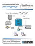
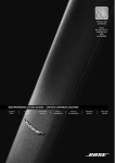
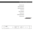
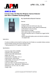
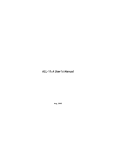
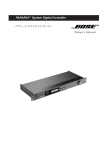
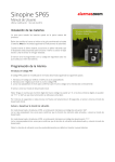
R
Installation and Operation Instructions
Wireless Network Sensor (SNR)
for PLATINUM CONTROLS With COMMUNICATION
The New Heat-Timer Wireless Network Sensor System is designed to be utilized in a variety of large buildings, garden apartments,
and in retrofit applications, giving both the accuracy and flexibility required to monitor those buildings' temperatures. The system will
ease the installation of space sensors in buildings were it would be difficult or cost prohibitive utilizing other means. Thus, allowing
Heat-Timer Platinum controls with communication access to the wireless sensor data. The values read from the wireless system are
used by the Platinum controls for monitoring, fine-tuning its operation, and logging its data.
The primary integral components of the system are: the Network Manager (NM), the Transceivers (TRV), the Wireless Sensors (SNR),
and finally, the Wireless Programmer (WP). The SNRs communicate their information to a nearby TRV or NM. The TRV transmit the
information down either to another TRV or to the NM. The NM communicates all the data it receives to the Platinum control. The WP
is the tool used to map, configure, diagnose, and troubleshoot the Heat-Timer Wireless Network System
Installation
SNR Emulation in RF Mapping (Survey)
A wireless survey of the building must be done prior to installing any wireless component. The survey involves the use of at least
two WPs (Wireless Programmers). Each of the WPs is set to emulate a different wireless component. Then, test communication and
signal strength between the different wireless components. Both signal strength readings (RSSI) should be above 50 for a reliable
connection. Upon receiving a good continuous signal strength, MARK the two locations of the WPs. These will be the locations of the
wireless components' installation. To set the WP to emulate each component, follow the steps.
Mounting Hole RS485 Connection
LEDs
Internal Antenna Hardware Version *
050131-00 REV.A
HEAT-TIMER CORP.
Green
Red
Button
Red
-
+
2 AA Alkaline Batteries *
-
+
2 AA Batteries *
Base Tabs
RF Module
Mounting Hole
* Hardware Model 050129-00 uses ONLY 3.6V AA Lithium batteries both mounted in the same direction
Hardware Model 050131-00 uses ONLY 1.5V AA Alkaline batteries mounted in the opposite direction
This equipment has been tested and found to comply
with the limits for a class B digital device, pursuant to
part 15 of the FCC Rules. These limits are designed
to provide reasonable protection against harmful
interference in a residential installation. This equipment
generates, uses, and can radiate radio frequency energy
and if not installed and used in accordance with the
instructions, may cause harmful interference to radio
communications. However, there is no guarantee that
interference will not occur in a particular installation. If
this equipment does cause harmful interference to radio
or television reception, which can be determined by
turning the equipment off and on, the user is encouraged
to try to correct the interference by one or more of the
following measures:
•Reorient or relocate the receiving antenna.
•Increase separation between the equipment and
wireless components.
•Connect the equipment into an outlet on a circuit
different from that to which the wireless components
are connected.
•Consult the dealer or an experienced radio/TV
technician for help.
2
Heat-Timer Corp.
Setting the System ID
•Make sure that the WP is fully charged.
•Power the WP on. That should turn its LED to Green.
•Select WP.Setup Mode from the Main menu by pressing the (Enter / ◄┘ ) button. Then,
type a System ID or press the (Down / ▼ ) button to select a random ID. To accept the new
System ID press the (Enter / ◄┘ ) button. Then, press the F button to load it into the WP.
•This will be followed by the Emulation Mode menu.
•Remember to record the System ID to help you in setting up the next WP to the same System ID.
WARNING
DO NOT use 0000 as a System ID to avoid errors in operation.
The Heat-Timer Wireless Network components can communicate only if they
have the same System ID.
Emulating Sensor (SNR)
•After setting the System ID on the WP, the Emulation menu will display.
•Select EMULATE SNR and Press the ◄┘ . The option for the transmission power will
follow.
•Select DETECT RSSI using the ◄┘ button followed by the F to accept.
•Press the Mode to go to the main menu.
•Select Auto Mode using the ▼ or ▲ buttons. Then press the ◄┘ button to
accept. Within a few seconds, signal strength data should display.
•The numbers below the MASTER and WPROG represent the signal strength received by each of
the components from the other component. That is, the number below MASTER represents how
well the MASTER received current WPROG signal.
•The fourth display line contains T01 which represents the master's ID. A 00 represents the
NM. Any ID that starts with the T or R represents a TRV.
•The NEW 01A represents the next TRV ID upstream available.
Setting the Wireless Configuration
For the SNRs to function in a wireless system, each must communicate to a nearby TRV
(Transceiver) or NM (Network Manager). Each wireless network should have a unique System ID.
The System ID enables all wireless components with that ID to communicate to each other. The
WP is the only tool used to configure all system components and their parameters.
Setting the Wireless SNR System ID
•After setting the WP to the System ID, you'll need to configure the SNR with the System ID.
•To return to the main menu. press the Mode button
•Select Config devices from the Main menu by pressing the ◄┘ button. Then, select
System Id from the list by pressing the ◄┘ button. This will display the System ID
configured into the WP.
•Make sure that the phone cable is connected to the WP and the SNR to be programmed.
•Press the F button to load the System ID into the SNR.
•This will show ACK momentarily on the third line of the display acknowledging the SNR
acceptance of the new System ID.
-WP.SETUP mode
SYSTEM ID# C9E5
[UP] delete
[DWN] pick
◄┘
*CONFIG. MODE[9]
WP.Sys Id# C9E5
[F] to load
F
-WP.Setup mode
Emulate TRV
>Emulate SNR
Emulate NM
-WP.Setup mode
SNIFF
>DETECT RSSI
Accept Detect RSSI
◄┘
-WP.Setup mode
DETECT RSSI
[F] to load
Enter the Detect RSSI F
Config devices
Get device data
WP.Setup Mode
>
Auto Mode
Enter Auto Mode
◄┘
AUTO MODE
MASTER WPROG
65 62
T01 NEW 01A
Exit to Main Menu
Mode
>
Config devices
Get device data
WP.Setup Mode
Auto Mode
Accept Config Devices
◄┘
*CONFIG. MODE[9]
>
System Id
Reset Sensor
POWER dwn SNR
Select System ID
◄┘
*CONFIG. MODE[9]
WP.Sys Id# C9E5
[F] to load
To load the System ID F
Wireless Sensor System Installation and Operation Manual
3
Testing and Operating Wireless SNR
Depending on the SNR Hardware version, the type of batteries used varies.
WARNING
Normal Mode
•In the Normal Mode, the SNR will transmit data to the RTR or NM that can hear it. During that
process no LED lights will blink.
•If reliable communication to the last RTR or NM cannot be achieved, the SNR will try to send the
data to any RTR or NM in the same network.
2 AA Alkaline Batteries *
-
+
+
Green
As with any wireless component, for the SNR to function within a network, it must be programmed to
the network System ID using the Wireless Programmer (WP). A SNR with no System ID, as with new
SNRs from factory, will have all of its LED lights blinking when powered up.
-
+
Red
The SNR is designed to work with other Heat-Timer Wireless Network System components. The sensor
will measure the space temperature and transmit its data, using its internal antenna, to either a RTR or
a NM to pass it downstream the network to the Heat-Timer Platinum control. The SNR will send its
temperature, battery status, transmission and reception power, and address; at predetermined intervals.
Green
Red
Depending on the SNR hardware version, different batteries and batteries installation is required. If batteries
are to be installed in opposite direction (see sensor board battery insertion chart), use the 1.5V Alkaline
batteries. If batteries are to be installed in the same direction, use the Lithium 3.6V batteries. DO NOT use
the Lithium batteries with other electronic devices. These batteries can damage the device they are used on.
-
2 AA Lithium Batteries *
+
-
Install Mode
•By pressing and holding the SNR button for three seconds, it will get into the Install Mode. This can be identified by the continuous
Red blinking light on the main board. Whenever the data is received by a RTR or a NM, the Green LED on the SNR will blink once
indicating good reception.
•In the Install Mode, the SNR will try to search for a RTR or NM within the Wireless Network and then send its data.
•In the SNR Install Mode the SNR will transmit data at 15 second interval for a total of 15 minutes to allow for troubleshooting and
diagnoses. After the 15 minutes period, the SNR will revert to normal operation.
•To exit this mode, press the button once. The SNR will exit the mode and revert to normal operation.
One Packet Mode
•The SNR can be set to send a single data packet by clicking the button once. Once done, the SNR RF Module LED will blink Red to
indicate data transmission. This is useful when testing SNR transmission operation or after installing the SNR on the web.
LED Indication
• Red RF Module LED: Blinks when transmitting data in Install Mode or One Packet Mode has been initiated.
• Red Main LED: Blinks when in Install Mode.
• Green Main LED: Blinks when in Install Mode and data reception by a RTR or NM has been acknowledged.
• Both Red LEDs:When both Red LEDs are blinking it indicates SNR requires System ID to be configured. This is
the default mode from the factory prior to configuration.
• All three LEDs:When all three LEDs are blinking it indicates an error. Try to disconnect the batteries for one minute
and then reconnect them. If all LEDs where blinking, call factory.
Mounting the Sensor (SNR)
•The SNR should be mounted on a wall that will represent the current living space temperature. Mount the SNR away from all heat,
cool, and humidity sources as in front of A.C. or close to windows.
•The ambient temperature at the SNR location should be between 32 and 150°F.
•Open the SNR Cover by inserting your thumb in the large rectangular opening at the bottom of the enclosure and gently pull it down
and out to open.
•Insert the batteries to activate the SNR. If the SNR was not programmed with the System ID, it will blink constantly. Make sure
there is a RTR or a NM that it can connect to.
•Connect the Wireless Programmer (WP) to the SNR using the WP phone cable (RS485).
4
Heat-Timer Corp.
•If the SNR is in Normal Mode (No lights are on) push and hold the button to start Install Mode Main Board.
•Using the WP send the System ID to the SNR and wait for ACK (acknowledgement). The SNR should automatically switch back to
Normal Mode. Otherwise, press the button once to exit the Install Mode.
•Mount the SNR base on the wall using the provided screws and the mounting holes.
•Replace the SNR cover.
Configuring the NM and TRV on the ICMS Webpage
•The Wireless Network Sensor System data
can only be read by any Platinum control with
communication option.
•If using the Internet Communication ICMS web
system (http://www.htcontrols.com), configure the
SNRs on the web to see their data. The Device ID,
Type, and Floor are required to configure any of the
wireless components.
•The easiest way to configure multiple wireless
devices is to log on to your account as a Full Rights
user. Then, start with the Functions button and
press Mass Device Changes. Select the Platinum
control and then select the Wireless Sensor/
TRCVRS button.
•List all your wireless devices using the Device ID,
Name, Type, and Floor Number. Try to provide
a meaningful name to each device to help in
identifying them later in other webpages as well as
in troubleshooting.
Troubleshooting
•The Wireless Network System can mostly be diagnosed over the web using the Wireless Diagnostic View that can be accessed from
the 3D building page.
•Primarily, the signal strength (RSSI), and the Battery Status are the most important information. The RSSI measures the signal
between the current device and it's downstream parent in both directions.
•If either of the RSSI measurement is below 50%, you can either move either the SNR or the TRV its communicating to. Start by
switching the sensor to Install Mode to help it locate a different TRV.
•If the Battery status indicates bad or low, then replace the sensor batteries.
Wireless Space Sensor Specifications
Frequency: . . . . . . . . . . . . . . . RF 900mHz FHSS
Signal Strength: . . . . . . . . . . . . . 25mw to 200mw
Power Input: . . . . 2 AA Lithium/2 AA Alkaline batteries
Transmission/Reception: . . . . . . . Built-in Antenna
Buttons: . . . . . . . . . . . . . . . . . . 1 wake up button
R
C O R P O R A T I O N
LED: . . . . . . . . . . . . . . . . 3 LED for status display
Temperature Range: . . . . . . . . 40°F to 150°F degree
Programming Interface: . . . . . . . . . . . . . RS485
Dimensions: . . . . . . . . . . . . . . 4-¾" x 2-⅝" x 1-¼"
Mounting: . . . . . . . . . . . . . . . . . . . . Wall Mount
20 New Dutch Lane, Fairfield, NJ 07004 973-575-4004 • Fax 973-575-4052 • http://www.heat-timer.com
059049-00 Rev.B