1
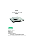
HI WS100 CONFIGURATION SOFTWARE
OPERATION AND INSTALLATION
MANUAL
Corporate Headquarters
3860 Calle Fortunada
San Diego, CA 92123-1825
Phone: (858) 278-2900
FAX: (858) 278-6700
Web-Site: http://www.hardyinst.com
Hardy Instruments Document Number: 0596-0241-01 REV A-1
Copyright November 1999 Hardy Instruments, Inc. All Rights Reserved. Printed in the U.S.A. (941028)
1-2
Table of Contents
Table of Contents
TABLE OF CONTENTS - - - - - - - - - - - - - - - - - - - - - - I
TABLE OF ILLUSTRATIONS - - - - - - - - - - - - - - - - - - - I
CHAPTER 1 - OVERVIEW - - - - - - - - - - - - - - - - - - - - - 1-1
A Brief Description of Chapter 1 - - About Hardy Manuals - - - - - - - Description - - - - - - - - - - - - - C2® Calibration - - - - - - - - - - IT - - - - - - - - - - - - - - - - - Weighing System Tests - Optional
-
-
-
-
-
-
-
-
-
-
-
-
-
-
- 1-1
- 1-2
- 1-2
- 1-3
- 1-3
- 1-4
CHAPTER 2 - REQUIREMENTS - - - - - - - - - - - - - - - - - - 2-1
General Introduction to Chapter 2 - - - - - - - - - - - - - - - Operating System Requirements - - - - - - - - - - - - - - - - Minimum Hardware Requirements - - - - - - - - - - - - - - - Software Requirements - - - - - - - - - - - - - - - - - - - - RSLogix OR EQUAL (FOR REMOTE MODE OPERATION ONLY)
- 2-1
- 2-1
- 2-1
- 2-1
- 2-1
CHAPTER 3 - INSTALLATION - - - - - - - - - - - - - - - - - - - 3-1
Installing the Hardy Instruments Configuration Software - - - - - - - 3-1
Installation of RSLOGIX - - - - - - - - - - - - - - - - - - - - - - 3-1
Installation of RSLINX or RSLINX Lite - - - - - - - - - - - - - - - 3-1
Wiring Diagram for the HI 215IT Junction Box - - - - - - - - - 3-2
CHAPTER 4 - SETUP - - - - - - - - - - - - - - - - - - - - - - - 4-1
A Brief Description of Chapter 4 - - - - - - - - - - - - - - - - - - 4-1
Presetup Procedures - - - - - - - - - - - - - - - - - - - - - - - - 4-1
Setup Procedures - - - - - - - - - - - - - - - - - - - - - - - - - 4-3
Comm Setup for SLC Models (Except SLC 5/02) - - - - - - - - 4-3
Comm Setup for the SLC 5/02 - - - - - - - - - - - - - - - - - 4-5
Comm Setup for the HI 1746WS Remote Rack - - - - - - - - - 4-7
i
HI WS100 CONFIGURATION SOFTWARE
CHAPTER 5 - OPERATING PROCEDURES - - - - - - - - - - - -5-1
A Brief Description of Chapter 5 - - Reading Live Weight, - - - - - - - Taring the HI 1746-WS - - - - - Zeroing HI 1746-WS - - - - - - Relay 1 and Relay Status - - - Setting the ROC Units - - - - - Errors - - - - - - - - - - - - - Calibration Procedures - - - - - - - C2 Calibration - - - - - - - - - Hard Calibration Procedures - - Soft Calibration - - - - - - - - Setting Parameters - - - - - - - - - Set Point Setup Procedures - - - - About Set Points - - - - - - - - Three General Rules for Set Points
Reading C2 Load Cell Serial Numbers
Remote Screen - - - - - - - - - - -
-
-
-
-
-
-
-
-
-
-
-
-
-
-
-5-1
-5-1
-5-1
-5-2
-5-2
-5-2
-5-2
-5-2
-5-2
-5-3
-5-4
-5-5
-5-8
-5-8
-5-8
-5-9
-5-10
CHAPTER 6 - TROUBLESHOOTING
- - - - - - - - - - - - - - -6-1
A Brief Description of Chapter 6 - - - - - - - - - - - - - - - - - -6-1
IT Troubleshooting - - - - - - - - - - - - - - - - - - - - - - - - -6-1
ii
Table of Illustrations
Table of Illustrations
CHAPTER 3 - INSTALLATION - - - - - - - - - - - - - - - - - - - 3-1
FIG. 3-1 C2 LOAD CELL CONNECTION/HI 215IT
JUNCTION BOX - - - - - - - - - - - - - - - - - - - - - 3-2
FIG. 3-2 NON C2 LOAD CELL CONNECTION/HI 215IT
JUNCTION BOX - - - - - - - - - - - - - - - - - - - - - 3-3
CHAPTER 4 - SETUP - - - - - - - - - - - - - - - - - - - - - - - 4-1
FIG. 4-1
FIG. 4-2
FIG. 4-3
FIG. 4-4
INTRO PAGE - - - - - - - - - - - - - - - - - - - - COMM SETUP - - - - - - - - - - - - - - - - - - - - REMOTE SELECTED/ENTER FILE#, STARTING WORD
SAMPLE OF REQUIRED LADDER LOGIC
FOR INTEGER TYPE FILES SLC 5/02 - - - - - - - - FIG. 4-5 CHECKING “USE INTEGER FILE. . . “/SLC 5/02 - - - FIG. 4-6 HI 1746WS REMOTE RACK LADDER LOGIC - - - - -
- 4-3
- 4-4
- 4-5
- 4-6
- 4-7
- 4-11
CHAPTER 5 - OPERATING PROCEDURES - - - - - - - - - - - - 5-1
FIG. 5-1
FIG. 5-2
FIG. 5-3
FIG. 5-4
FIG. 5-5
FIG. 5-6
FIG. 5-7
FIG. 5-8
LIVE WEIGHT PAGE - - - - - C2 CALIBRATION - - - - - - HARD CALIBRATION - - - - SOFT CALIBRATION - - - - - PARAMETERS SETTINGS - - SETPOINT SCREEN - - - - - C2 SERIAL NUMBER SCREEN
REMOTE DISPLAY - - - - - - -
CHAPTER 6 - TROUBLESHOOTING
-
-
-
-
-
-
-
-
-
-
-
-
- 5-1
- 5-3
- 5-4
- 5-5
- 5-6
- 5-8
- 5-10
- 5-11
- - - - - - - - - - - - - - - 6-1
FIG. 6-1 INTEGRATED TECHNICIAN TEST - - - - - - - - - - - - 6-1
I
Chapter 1 - Overview
CHAPTER 1 - OVERVIEW
A Brief Description of
Chapter 1
This manual provides the user and service personnel
with a description of the specifications, installation,
setup, operation, communication procedures for the
Hardy Instrument’s HI 100WS Configuration Software to configure the HI 1746-WS Weigh Scale Module, designed for use in Allen-Bradley’s SLC 5/02©,
5/03, 5/04, 5/05 programmable controllers. Chapter 1
provides a general introduction to the HI WS100 Configuration Software. The HI 100WS Software is C2®
and INTEGRATED TECHNICIAN (IT)® enabled. The HI
100WS Software is designed to run on the Windows®
95/98/NT/2000 platforms in conjunction with AllenBradley’s RS Linx© or RS Linx Lite© Industrial Programming Software for Windows® 95/98/NT/2000.
To get the maximum service from this product, users
should operate this software in accordance with recommended practices either implied or expressed in
this manual. Before using the HI WS100 Software, all
users and maintenance personnel should read and
understand all cautions, warnings, and safety procedures, referenced or explicitly stated in this manual.
Hardy Instruments appreciates your business. Should
you not understand any information in this manual or
experience any problems with the product, please
contact our Customer Support Department at:
Phone: (858) 278-2900
FAX: (858) 278-6700
e-mail: [email protected]
Web Address: hardyinst.com
NOTE:
C2®, INTEGRATED TECHNICIAN® are registered trademarks of Hardy Instruments Inc. Windows® is a registered trademark of the Microsoft Corporation.
RSLinx© and RSLinx Lite© SLC 500©are registered
trademarks of the Rockwell Corporation.
NOTE:
Hardy Instruments bases all procedures on the
assumption that the user has an adequate understand1-1
HI WS100 CONFIGURATION SOFTWARE
ing of all Allen-Bradley SLC 500 products. In addition the user should understand process control and
be able to interpret ladder logic instructions necessary to generate the electronic signals that control
your application(s).
About Hardy Manuals
Every Hardy Installation and Operation manual is
organized into easily referenced chapters, that are
almost always the same:
• Chapter 1 - Provides an introduction to the
instrument and an Overview of the equipment and its capabilities.
• Chapter 2 - Provides a complete list of
Specifications.
• Chapter 3 - Contains information needed to
install the HI 1746-WS (both standard and
optional equipment) and the HI 215IT series
Junction Box.
• Chapter 4 - Provides complete hardware
Configuration instructions for setting dip
switches and jumpers.
• Chapter 5 - Pertains to the firmware/software Setup and preparation procedures to
calibrate and operate the instrument.
• Chapter 6 - Provides all Calibration
instructions.
• Chapter 7 - Pertains to the Operating Procedures of the HI 1746-WS.
• Chapter 8 - Pertains to the Troubleshooting procedures for repair of the instrument.
Hardy Instruments hopes that this manual meets your
needs for information and operation. All corrections
or suggestions for improvements of this manual are
welcome and can be sent to the Technical Publications Department or Customer Support Department at
Hardy Instruments Inc.
Description
1-2
The HI WS100 Configuration Software is a program
that enables the user to configure a remote HI 1746WS Weigh Scale Module. The HI 1746-WS Weigh
Scale Module is a self contained microprocessor
based I/O module with control inputs and outputs, that
is designed to be easily plugged into the back plane of
Chapter 1 - Overview
an Allen-Bradley SLC 5/02, 5/03, 5/04 or 5/05 programmable controller and/or Remote Rack. The HI
100WS is IT enabled which means you can perform
the INTEGRATED TECHNICIAN (IT) Tests.
C2® Calibration
C2 Second Generation Calibration enables a scale
system to be calibrated electronically without using
certified test weights which equal the systems load
capacity. A C2 weighing system consists of up to
eight (8) C2 load sensors, a junction box, interconnect
cable and an instrument with C2 capabilities such as
the HI 1746-WS Weight Scale Module. All Hardy
Instruments C2 certified load sensors contain digital
information detailing its unique performance characteristics. If the system is fitted with C2 type load cells
the HI WS100 software displays the serial numbers
programmed into each load cell. From the serial numbers the operator can look up the parameters of each
loadcell by going to the Hardy Instruments Internet
Site. http://www.hardyinst.com
IT
INTEGRATED TECHNICIAN® is a system diagnostics
utility which continuously monitors the weighing system (with up to 4 load sensors) for possible malfunctions. For full functionality the HI 215IT junction box
(J Box) should be used. Full IT functionality allows
the operator to rapidly troubleshoot a weighing system from the HI 100WS Configuration Software,
Parameters Edit Display. The test are:
•
•
Loadcell Impedance - The user can see the
impedance determined at calibration (Base
R), the impedance found during the test
(Read R), and the test result (Good or Bad).
also shown are the volts at the loadcells at
calibration (Sense V), and the current going
to the load cells at the time of the reading.
RTZ - (Return to Zero) This test gives a
pass/fail on whether there is a zero load. If
you have a “J Box”, individual load cells can
be tested. If you do not have a :”J Box” the
test is done on the combined loadcells.
1-3
HI WS100 CONFIGURATION SOFTWARE
•
•
Weighing System
Tests - Optional
DVM - (Digital Volt Meter) If you have a “J
Box”, the voltage outputs from the individual loadcells can be read. If you do not have
a “J Box” the voltage is a combined voltage
output from all loadcells in the system.
System Test - If you have a “J Box” you
can read the weight being read on individual
load cells and the internal reference.
Requires the HI 215IT Junction Box. This test is used
to diagnose drifting or unstable weight reading problems. The Weighing System Test does the following:
1.
1.
2.
Disconnects the controller and engages an internal reference signal to see if the problem is within
the instrument.
Disconnects the load sensors and engages an
internal (in the junction box) reference signal to
see if the cable between the instrument and the
Junction Box is causing the problem.
Reads the weight of each load sensor to see if the
load sensor might be causing the problem.
The ability to read the weight seen by each individual
load sensor allows use of this test to make cornering,
leveling and load sharing adjustments to the weighing
system.
1-4
Chapter 2 - Requirements
CHAPTER 2 - REQUIREMENTS
General Introduction
to Chapter 2
All the information in Chapter 2 pertains to the hardware and software requirements for HI WS100 Configuration Software. These requirements are the
minimum requirements for loading and operating HI
WS100 Configuration Software. Check to see if the
personal computer on which you want to install HI
WS100 Configuration Software, meets these requirements. It is very important that the user be familiar
with this section before installing or operating this
software.
Operating System
Requirements
HI WS100 Configuration Software runs on the following operating systems:
• Windows NT 4.0/2000
• Windows 95/98
Minimum Hardware
Requirements
HI WS100 Configuration Software requires
the following hardware:
•
•
•
•
•
CPU - Pentium® 133 MHz or better
3 MB free space on your hard drive
RAM - 16 MB
Monitors - SVGA, configured for 640 x 480
resolution or better
Floppy Drive - 3.5”, 1.44 MB drive or better
NOTE:
The HI WS100 must run in conjunction with Allen
Bradley’s RS LINX or RS LINX LITE therefore the HI
WS100 hardware requirements are in addition to
hardware requirements for RS LINX or RS LINX
LITE.
Software
Requirements
Allen Bradley’s RS LINX® or RS LINX® LITE software.
RSLogix OR EQUAL
(FOR REMOTE MODE
OPERATION ONLY)
Allen Bradley’s RSLOGIX® software or equivalent.
NOTE:
RSLOGIX® is a registered trademark of the Rockwell
Corporation.
2-1
HI WS100 CONFIGURATION SOFTWARE
2-2
Chapter 3 - Installation
CHAPTER 3 - INSTALLATION
Installing the Hardy
Instruments
Configuration
Software
Contact your local Hardy Representative or Hardy
Instruments Sales Department for information about
how to purchase the Hardy WS 100 Configuration
Software for Windows.
Step 1.
Step 2.
Step 3.
Step 4.
Step 5.
Step 6.
Step 7.
The SETUP program copies the required
files to your hard disk.
Run Windows NT/95/98/2000 and insert
the Configuration Installation System Disk
into the 3.5” floppy drive.
Click on START.
Click on Run.
In the Run field type the command:
a:setup. If your floppy drive is drive b
enter: b:setup.
Press the Enter key.
You can also use the Add/Remove Function in the Control Panel dialogue box.
1
Click on Start
1
Move the cursor to Settings.
1
Select Control Panel.
1
Double click on the Add/Remove Programs
icon.
1
Click on the Install button.
Step 8.
The SETUP program will lead you
through the installation process.
Installation of
RSLOGIX
Please refer to your Allen Bradley Installation and
Operation manual for instructions.
Installation of RSLINX
or RSLINX Lite
Please refer to your Allen Bradley Installation and
Operation manual for instructions.
3-1
HI WS100 CONFIGURATION SOFTWARE
Wiring Diagram for
the HI 215IT
Junction Box
C2 Loadcell
Cable
Connection
(J1)
When connecting the HI 215IT Junction box using C2
loadcell/point cable (6020-0001) use the following
color code:
Model
EXC +
SEN +
SIG +
SIG -
SEN -
EXC -
C2 +
C2 -
J-BOX
RED
BLUE
GRN
WHT
BRWN
BLK
GREY
VIO
Table 1: C2 CABLE COLOR CODE/HI 215IT J-BOX
FIG. 3-1 C2 LOAD CELL CONNECTION/HI 215IT JUNCTION BOX
1
2
3-2
Recommended load cell cable, Hardy Instruments (Prt. #6020-0001)
Attach the load shield to the terminal block
mounted next to the J1 connector on the HI
200DNWM Module.
Chapter 3 - Installation
3
4
5
Non-C2
Loadcell Cable
Connection
(J1)
1
2
3
4
Do not run load cell cable in parallel with or
in the same conduit with power wiring, relay
cables or any other high energy cables.
Remove the factory installed jumpers for C2
wire load cell connection.
IT summing Card (Prt. #0535-0465)
Attach the load cell cable to the terminal
block mounted next to the J1 connector on
the HI 200DNWM Module.
Factory installed jumpers to remain in place
for 4 wire load cell connection.
Do not run load cell cable in parallel with or
in the same conduit with power wiring, relay
cables or any other high energy cables.
Eight (8) conductor load cell cable required
when:
•
•
Cable runs are greater than 50 feet.
With Soft Calibration
FIG. 3-2 NON C2 LOAD CELL CONNECTION/HI 215IT JUNCTION BOX
3-3
HI WS100 CONFIGURATION SOFTWARE
3-4
Chapter 4 - Setup
CHAPTER 4 - SETUP
A Brief Description of
Chapter 4
All information contained in Chapter 4 pertains to
firmware and software settings to prepare the HI
1746WS Weight Module controller for calibration
and operation. Alternatives to these procedures
explicit or implied, contained in this section are not
recommended. It is very important that the user and
service personnel be familiar with the procedures contained in this chapter, before going through the setup
procedures. The Setup procedures require either
Allen-Bradley DOS PLC 500 AI Series Ladder Logic
Editor*, or Allen-Bradley RSLogix 500* and AllenBradley RSLinx™ or RSLinx™ Lite.
Presetup Procedures
Step 1.
Step 2.
Step 3.
Step 4.
Step 5.
Step 6.
Step 7.
Make sure that the HI 1746-WS is
installed in the rack correctly.
Make sure that the HI 1746-WS has been
setup correctly and that all data necessary
to run the HI 1746-WS module has been
entered into RSLogix 500 configuration
software.
Check the module ID code to verify that
the jumper has been set for the proper
mode of operation (Local ID Code =
13635, Remote ID Code = 3235). If you
have put the HI 1746-WS module in a
local rack and get the 3235 ID number the
jumper is set incorrectly.
If you have set the jumper for the HI 1746WS module for local mode of operation
and placed the module in a remote rack the
1747 ASB will display an invalid module
error.
If these errors occur, remove the HI 1746WS and reset the jumper to the proper
mode of operation. (See the HI 1746-WS
Weigh Module Installation and Operation
Manual (Prt. #0596-0234-01), Chapter 3,
Page 3-2 for instructions)
Reinstall the module.
Repeat Steps 3 & 4.
4-1
HI WS100 CONFIGURATION SOFTWARE
NOTE:
If you are using RSLogix 500, the HI 1746-WS (in
local mode) is configured as an “Other” card with an
I/O module ID code of 13635, M0 and M1 lengths are
128.
NOTE:
If you are using RSLogix 500, the HI 1746-WS (in
remote mode) is configured as an “Other” card with
an I/O module ID code of 3235, with two input words
and two output words. In remote mode the HI 1746WS has no M files. Instead, it has files inside that correspond to the 32 word I and O files of the local mode
HI 1746-WS, and to its M files. These files are called
“logical” files, meaning that they perform the function of the I,O, and M files in the local mode but are
not directly accessible through the SLC backplane.
Step 8.
NOTE:
If you are starting HI WS100 for the first time you will
get a “Communication Failure” message. Don’t
worry about this message at this time. The Comm
Setup has not been configured yet. Once the HI
WS100 has been configured correctly the “Communication Failure” message goes away.
Step 9.
4-2
Double click on the HI WS100 Icon on
your Windows Desktop. The HI WS100
will automatically launch RSLinx.
The Intro Sheet displays with the setup
instructions in a text field. (See Fig. 4-1)
Scroll through the Text field and read the
instructions for setting up the HI 100WS
Configuration Software before starting the
setup procedures.
Chapter 4 - Setup
FIG. 4-1 INTRO PAGE
Setup Procedures
Comm Setup for
SLC Models
(Except SLC 5/02)
Step 1.
Click on the Comm Setup Tab. The Comm
Setup Page appears. (See Fig 4-2)
4-3
HI WS100 CONFIGURATION SOFTWARE
FIG. 4-2 COMM SETUP
Step 2.
Step 3.
Step 4.
CAUTION:
DO NOT CLICK IN THE CHECK BOX NEXT TO
THE “USE DTSA.TXT FILE”.
Step 5.
4-4
Enter the SLC slot number of the installed
HI 1746-WS Weigh Module in the Slot
textfield.
Enter the Station number of your SLC in
the Station textfield. This number must be
an Octal number for the Station number.
Select a driver (supplied by RSLinx) by
clicking on the down arrow on the
“Driver” pull down menu. Click on the
driver you want to use to communicate
with the HI 1746-WS.
If the HI 1746-WS module is installed in a
remote rack, click in the check box next to
the word “Remote?”. (See Fig. 4-3)
Chapter 4 - Setup
FIG. 4-3 REMOTE SELECTED/ENTER FILE#, STARTING WORD
Step 6.
Step 7.
Step 8.
Comm Setup for
the SLC 5/02
Enter the integer number used in the Ladder Logic for remote operation of the HI
1746-WS Weigh Module in the textfield
next to “File#”. In our example we entered
the number 7.
Enter the starting number us in the Ladder
Logic for remote operation of the HI 1746WS Weigh Module in the textfield next to
“starting word”.
Click on the Save button to save the settings.
Normally the HI WS100 talks to the HI 1746-WS via
the “M Files”. The SLC 5/02 does not support communication commands for direct reading and writing
of M Files. The SLC 5/02 supports commands to read
and write “integer” type files.
Step 1.
Write the ladder logic provided (See Fig.
4-4) to copy the integer file to the HI
12746-WAS’s M files. The ladder logic
4-5
HI WS100 CONFIGURATION SOFTWARE
enables the HI 1746-WS to read the information in the integer file.
FIG. 4-4 SAMPLE OF REQUIRED LADDER LOGIC FOR INTEGER TYPE
FILES SLC 5/02
NOTE:
Our example has the HI 1746-WS weigh module
located in slot #3 of the SLC and the integer file #9
(N9) is chosen with the starting word = 0.
Step 2.
4-6
Click in the check box next to the “Use
integer file (required by 5/02, needs ladder
logic support)”. (See Fig. 4-5) The program will write to the specified integer file
number (7,8,9, etc. for N7, N8, N9,. . .)
starting at the specified offset (starting
word) within that file. The program
Chapter 4 - Setup
requires a total of 43 integer words: 21 for
the M0 file, 21 for the M1 file, and 1 as a
flag.
FIG. 4-5 CHECKING “USE INTEGER FILE. . . “/SLC 5/02
Comm Setup for
the HI 1746WS
Remote Rack
Legend
The ladder logic example below must be running so
that the WS100 Configuration Software will work
with the 1746 module installed in a Remote Rack. The
addresses shown in the ladder logic example are arbitrary locations. If the file is added to an existing program, these address locations can be changed for the
system to insure there are no conflicts. The color coding of the locations is as follows:
Green: Slot # for scanner module in local
rack and portion of the M file to be
used.
Yellow: Integer files used for data defining
the M file, (read/write, length,
address). Also status/error bits pertaining to the transfers of data.
4-7
HI WS100 CONFIGURATION SOFTWARE
Pink:
Integer file specified in the WS 100
program COMM SETUP screen
that it will use to read/write data.
The WS 100 Configuration Program also specifies the starting
word in this file. The WS 100 will
17 words starting at the specified
word of the file. The first word is
used as a trigger to start the write
process. Words 2-9 are the write
data, and words 10-17 are the read
data.
No Color:
4-8
Status bits used for program control.
Chapter 4 - Setup
4-9
HI WS100 CONFIGURATION SOFTWARE
4-10
Chapter 4 - Setup
FIG. 4-6 HI 1746WS REMOTE RACK LADDER LOGIC
4-11
HI WS100 CONFIGURATION SOFTWARE
4-12
Chapter 5 - Operating Procedures
CHAPTER 5 - OPERATING PROCEDURES
A Brief Description of
Chapter 5
All information contained in Chapter 5 pertains to the
operation of the HI WS100 Configuration Software.
The Operating Procedures include, Reading Live
Weight, Calibration, Creating or modifying Setpoint(s) Parameters, reading C2 load cell serial numbers and quickly monitoring Gross Weight (remote
modules only) for the HI 1746-WS Weigh Module.
NOTE:
The HI WS100 will not read non-C2 load cell serial
numbers.
Reading Live Weight,
Step 1.
Click on the Live Weight Tab. The Live
Weight page appears. (See Fig. 5-1) The
Gross, Net and Tare weights are displayed.
In addition the Rate of Change (ROC) and
the ROC Units are displayed. Relay 1 and
Relay 2 status are displayed.
FIG. 5-1 LIVE WEIGHT PAGE
Taring the HI 1746WS
Step 2.
To Tare the HI 1746-WS click on the Tare
button.
5-1
HI WS100 CONFIGURATION SOFTWARE
Zeroing HI 1746WS
Step 3.
To Zero the HI 1746-WS click on the Zero
button.
Relay 1 and Relay
Status
Step 4.
The Relay 1 and Relay 2 status fields display only two values:
•
Low = O voltage output
•
High =5 volts output.
Setting the ROC
Units
Step 5.
Click on the radio button next to the unit
you want to use for the Rate of Change.
(Default is Minute)
Errors
Step 6.
The lights next to Motion, Excite Error, A/
D Conversion Error and A/D Convertor
Failure should all be green. A red light
indicates an error in the weight readings.
Step 1.
Click on the Calibrate Tab. The Calibration page appears. (See Fig. 5-2)
HI WS100 gives you three choices for
Calibration:
Calibration
Procedures
Step 2.
•
•
•
C2 Calibration
Step 3.
Step 4.
5-2
C2 Calibration
Hard Calibration
Soft Calibration
Click in the radio button next to C2. The
C2 Cal parameters appear. (See Fig. 5-2)
Follow the instructions in the Text Area
Field for C2 Calibration. For additional
information consult your HI 1746-WS
manual (Prt. #0596-0234-01) Chapter 5 Calibration.
Chapter 5 - Operating Procedures
FIG. 5-2 C2 CALIBRATION
Hard Calibration
Procedures
Step 1.
Step 2.
Click on the radio button next to Hard Calibration. The Hard Calibration parameters
appear. (See Fig. 5-3)
Follow the instructions in the Text Area
Field for Hard Calibration. For additional
information consult your HI 1746-WS
manual (Prt. #0596-0234-01) Chapter 5 Calibration.
5-3
HI WS100 CONFIGURATION SOFTWARE
FIG. 5-3 HARD CALIBRATION
Soft Calibration
Step 1.
Step 2.
5-4
Click on the radio button next to Soft Calibration. The Soft Calibration parameters
appear. (See Fig. 5-4)
Follow the instructions in the Text Area
Field for Soft Calibration. For additional
information consult your HI 1746-WS
manual (Prt. #0596-0234-01) Chapter 5 Calibration.
Chapter 5 - Operating Procedures
FIG. 5-4 SOFT CALIBRATION
Setting Parameters
Step 1.
Step 2.
Step 3.
Click on the Parameter Tab. The Parameter page appears. (See Fig. 5-5)
Set the Tare weight - Double click in the
Tare Weight field and enter the Tare
Weight Value. The Tare Value is an artificial zeroing of the weight hopper so that a
new weight can be displayed. Also, the
action of adjusting out the known weight
of the container from the total indicated
weight, so that the indicator reads net
weight directly. You must click in the
check box next to Tare Enabled to enable
the Tare Function.
Set the Weight Unit of measure - The
Weight Unit of Measure can be set to
either kilograms or pounds. Any weight
value input to the module (e.g. CAL-LO,
CAL-HI setpoints) are in the currently
selected units. The unit of measure can be
set at any time, not just at calibration. Setting the unit of measure before calibrating
reminds the user what unit of measure is
5-5
HI WS100 CONFIGURATION SOFTWARE
Step 4.
being displayed. It is important to note that
the weigh scale module does not need to
be calibrated again after changing the unit
of measure.
Set the WAVERSAVER level - There are
5 selectable levels. 0 provides the least
vibration immunity with the fastest
response time. 4 provides the most vibration immunity with the slowest response
time. The Default setting is 2. Click on the
pull down menu next to WAVERSAVER
and click on your selection.
FIG. 5-5 PARAMETERS SETTINGS
Step 5.
5-6
Set the Number of Averages (NumAverages) - Click on the up or down arrow to
reach the value you want or double click in
the field and enter the value. The range is
1-255. The Number of Averages sets the
number of weight readings which will be
used to compute the displayed weight. The
average is a sliding average so that a new
average reading is available for display at
every reading.
Chapter 5 - Operating Procedures
Step 6.
Step 7.
Step 8.
Set the ROCTimeBase - Click on the up
or down arrow to reach the value you want
or double click in the field and enter the
value. The Rate of Change Time Base is
the time period you want for weight sampling to determine the Rate of Change,
either loss in weight or gain in weight. The
range is 1 - 1800 seconds.
Set the Zero Tolerance - Double click in
the Zero Tolerance field. The default value
is 10 units of measure. Enter the new Zero
Tolerance value. The range is 1 to 32766.
Zero Tolerance sets the range of weights
so that the Zero Command works, as an
offset of the calibrated Zero. Zero Tolerance is the number of graduations from
zero that will be accepted as zero by the
module. To enable Zero Tolerance click in
the check box next to “Zero Enabled” so
that a check mark is visible. The operator
can reset this value at any time.
Set the Auto Zero Tolerance - The
default value is 10 units of measure. The
range is 1 to 32766.
•
Step 9.
Double click in the Auto Zero Tolerance field.
• Enter a positive value that does not
exceed the maximum zero tolerance
value or is not a negative value.
• Click in the check box next to ”Zero
Track Enabled” to activate Auto
Zero Tolerance tracking.
• The Auto Zero Tolerance setting
automatically sets the Zero Tolerance so that the Zero Command
works, as an offset of the calibrated
Zero.
Set the Motion Tolerance Value - Click
in the Motion Tolerance field and enter the
motion value. The motion tolerance is the
tolerance value used to determine if the
scale is in motion. If the motion is outside
5-7
HI WS100 CONFIGURATION SOFTWARE
the motion value entered, the light next to
Motion Tolerance will turn to red. When
the scale motion is within the tolerance the
light turns green.
Step 10. Click on the Save button to save the new
parameters.
Set Point Setup
Procedures
About Set Points
The set point value is the target weight or level. It may
be set in net, gross or Rate of Change (ROC). When
the set point is reached a relay is energized or de-energized depending what you want the relays to do. The
HI 1746-WS has two output relays which can be setup
in HI WS100 Configuration Software.
Step 1.
Click on the Setpoint Tab. The Setpoint
page appears. (See Fig. 5-6)
FIG. 5-6 SETPOINT SCREEN
Three General
Rules for Set
Points
5-8
1.
2.
Set points activate at the set point plus the preact.
Set points deactivate at the set point plus the
deadband.
Chapter 5 - Operating Procedures
3.
The deadband should be numerically larger than
the preact to prevent relay chatter.
Step 2.
Step 3.
Step 4.
Step 5.
Double click in the Value field.
Enter the desired set point value.
Double click in the Preact field.
Enter the desired Preact value. Preact is
the number of units above or below the set
point value of which the relay will trip.
Use as an “in flight” compensation value.
Step 6. Double click in the Deadband field.
Step 7. Enter the desired Deadband value. Deadband is a value used to prevent relay chatter once the setpoint is reached. You can
use positive or negative values. The negative value can be used as a low trip limit,
the positive value can be used as a high
trip limit.
Step 8. Click in the radio button next to the Setpoint Mode you want.
Step 9. Click in the radio button next to the Value
units you want to read the weight. Gross,
Net, or ROC.
Step 10. Click on the Save button to save the settings.
Reading C2 Load Cell
Serial Numbers
Step 1.
Step 2.
Click on the C2 Tab. The C2 page
appears. (See Fig. 5-7)
Go to the Hardy Internet Site (http://
www.hardyinst.com) where you can look
up the parameters of your load cell(s).
5-9
HI WS100 CONFIGURATION SOFTWARE
FIG. 5-7 C2 SERIAL NUMBER SCREEN
Remote Screen
Step 1.
NOTE:
The Remote Display will only appear if the HI 1746WS module is installed in a remote chassis, with the
jumper set to the remote mode of operation.
Step 2.
Step 3.
5-10
Click on the Remote Tab. The Remote
page appears. (See Fig. 5-8)
The Remote screen is a quick way to monitor gross weight of an HI 1746-WS module, installed in a remote chassis and
operating in the remote mode. This screen
gives the user a faster Gross Weight reading than the Live Weight display.
The indicator lights for Motion, and A/D
Conversion and A/D Converter should all
be green in normal operation. A motion
red light means the scale exceeds the
Motion Tolerance setting. A/D Conversion
and A/D Converter red lights means a malfunction.
Chapter 5 - Operating Procedures
FIG. 5-8 REMOTE DISPLAY
5-11
HI WS100 CONFIGURATION SOFTWARE
5-12
Chapter 6 - Troubleshooting
CHAPTER 6 - TROUBLESHOOTING
A Brief Description of
Chapter 6
Chapter 6 provides instructions on how to use Hardy
Instruments INTEGRATED TECHNICIAN™ to perform
various tests for fault isolation troubleshooting of the
load cells in your weighing system. INTEGRATED
TECHNICIAN used in conjunction with the HI 2215IT
Junction Box can tell you which load cell is not functioning properly, thereby eliminating the necessity of
having to physically go to the load cell for testing.
You can see from your PC desktop which cell is not
working properly.
IT Troubleshooting
Step 1.
Click on the Integrated Technician tab. the
Integrated Technician page appears. (See
Fig. 6-1)
FIG. 6-1 INTEGRATED TECHNICIAN TEST
Step 2.
In the “Number of Sensors (JBox only)”
field you will see an up and down arrow. A
few things need to be said about this field.
•
If you have all C2 load cells and an HI
215IT Junction Box, when you calibrate
6-1
HI WS100 CONFIGURATION SOFTWARE
the instrument, HI WS100 automatically
loads the number of C2 load cells that
are incorporated in your weight system.
The number will automatically display
in the Number of Sensors field. Having
the HI 215IT Junction Box enables the
configuration software to list the test
results for each individual load cell in
your weighing system.
If you have non-C2 load cells and an Hi
215JT Junction Box, then you need to
add the number of load cells in your system by clicking on the up or down
arrows or double clicking in the field
and typing the number, to enter the
number of load cells in your weight system. Having the HI 215IT Junction Box
enables the configuration software to list
the test results for each individual load
cell in your weighing system.
If you do not have the HI 215IT Junction Box, the configuration software will
give you a combined test result of all the
load cells in your weighing system. (See
Fig. 6-1)
•
•
Step 3.
Click on the Test button. After a second or
two the results of the test will appear in the
fields. The tests are:
1.
Loadcell Impedance
•
•
•
NOTE:
6-2
Base R is the impedance at the
time of the last Calibration.
Read R is the impedance reported
during the test.
Test R indicates whether the cell
is good or bad.
Keep in mind that if you have the HI 215IT Junction
Box the Test R result will appear for each load cell.
Therefore you will know exactly which load cell
failed. If you do not have an HI 215IT Junction it will
Chapter 6 - Troubleshooting
give a combined fail result but not for the specific
load cell that failed. You will still have to determine
which Load Cell failed.
2.
Return to Zero Test (RTZ) - This test
returns a pass/fail result on whether
there is a zero load.
•
•
3.
Digital Volt Meter (DVM) - This test
returns the voltage outputs from the
load cells.
•
•
4.
If you have an HI 215IT Junction
Box, individual load cells can be
tested.
If you do not have an HI 215IT
Junction box the result will be for
the combined load cells in your
weighing system.
If you have an HI 215IT Junction
Box, the voltage output for each
individual load cell is read.
If you do not have an HI 215IT
Junction box the voltage output
read will be for the combined
load cells in your weighing system.
System Test - Reads the weight for
the load cells in your system.
•
•
If you have an HI 215IT Junction
Box, the weight for each individual load cell can be read as well
as the internal reference.
If you do not have an HI 215IT
Junction box the weight read will
be combined weight for all the
load cells in your weighing system.
6-3